Download - EZWatch

Transcript
Table of Contents
About This Guide ------------------------------------------------------------------------------ 6
FCC Compliance Statement ------------------------------------------------------------- 6
FCC Warning-------------------------------------------------------------------------------------- 6
License Agreement --------------------------------------------------------------------------- 7
Software Product License----------------------------------------------------------- 7
Upgrades: -------------------------------------------------------------------------------- 8
Trademark ----------------------------------------------------------------------------------------- 9
Customer Support ---------------------------------------------------------------------------- 9
Chapter 1 Product Introduction-----------------------------------------------------10
1-1. Product Features ---------------------------------------------------------------10
Chapter 2 Software Installation ----------------------------------------------------16
2-1. Software System Requirements --------------------------------------16
2-1-1. EZWatch Pro---------------------------------------------------------------16
2-1-2. EZNetwork and EZModem ----------------------------------------17
2-2. Installation Prerequisites -------------------------------------------------18
2-3. Installing EZWatch Pro 3.1 HD Software ------------------------18
2-4. Video Board and Driver Installation --------------------------------24
2-5. Setup Windows XP to run EZWatch Pro 3.1 HD -------------26
2-6. Software Installation Procedures ------------------------------------28
2-6-1. EZNetwork Installation Procedures (TCP/IP) -------28
2-6-2. EZModem Installation Procedures --------------------------29
2-6-3. PDAView Pro Installation Procedures---------------------31
Chapter 3 System Configuration----------------------------------------------------32
3-1. EZWatch Pro Functions Overview------------------------------------32
3-2. How to Prevent System Crashes--------------------------------------33
3-2-1. Power Management Setup ---------------------------------------34
3-2-2. Windows File System Setup -------------------------------------34
3-2-3. How to setup System Reboot Schedule ------------------34
2
3-3. EZWatch Pro System Configuration --------------------------------36
3-3-1. Set up video Parameters-EzSetup ---------------------------36
Chapter 4 EZWatch Pro System Operation -----------------------------------40
4-1. Surveillance Server Program--------------------------------------------40
How to change the video parameters? -------------------------------42
4-1-1. How to Login to EZWatch Pro
-------------------------------44
4-1-2. Camera Configuration
--------------------------------------------44
4-1-2-1. General -------------------------------------------------------- 44
4-1-2-2. Recording ---------------------------------------------------- 45
4-1-2-2-1.
Set up the recording schedule -- 46
4-1-2-3. Motion Setting -------------------------------------------- 58
4-1-2-4. Video Loss --------------------------------------------------- 61
4-1-2-5. POS & FingerKey (Optional) -------------------- 62
4-1-3. EzSyncPlayback
-----------------------------------------------------65
4-1-4. Playback Video Clips
4-1-5. Network Configuration
----------------------------------------------71
------------------------------------------73
4-1-6. System Configuration/EzTools
-----------------------------75
4-1-7. Setup Privileges
------------------------------------------------------80
4-1-8. View Log
------------------------------------------------------------------81
4-1-9. Setup I/O
----------------------------------------------------------------82
a.) Setup relay (Optional) ----------------------- 83
b.) Control NetCom Module relay (Optional) -- 84
c.) Setup NetCom Module sensor (Optional) - 84
d.) Emergency call ------------------------------- 85
e.) Fingerprint Access Control ------------------ 86
4-1-10. Storage Device Configuration
------------------------------86
4-1-11.Video Control Panel ------------------------------------------------------88
4-2. Back up system-EzBackup
-----------------------------------------91
4-3. Web Browse Server – EzWebServer
3
--------------------------93
4-4. LAN Play Back Video Clips – EzLanPlayback
4-5. Play Back Video Clips – EzPlayback
4-6. Text insert Playback – EzTextPlayback
------------97
------------------------- 100
------------------- 102
4-7. Remote Control Server– EzRServer
------------------------ 102
4-8. Two Way Communication – EzSTalk
----------------------- 103
4-9. Access Control – EzFingerKey
----------------------------------- 105
4-10.Uninstalling EZWatch Pro Software and Device Driver105
4-10-1. Uninstalling EZWatch Pro ------------------------------------- 105
4-10-2.Checking for or Uninstalling the Device Driver --- 106
Chapter 5 Remote Client PC Software ---------------------------------------- 110
5-1. How to use the Remote Client program ------------------------ 110
5-1-1. How to use EZNetwork ------------------------------------------- 110
5-1-2. How to use EZModem---------------------------------------------- 111
5-1-3. Free View Pro/EZModem Program Operation------ 113
5-1-4. Connecting to Local DVR SEVER ---------------------------- 115
5-1-5. Video Window Function Description --------------------- 118
5-1-6. Using the Site Book ------------------------------------------------- 121
5-1-7. System Configuration---------------------------------------------- 122
5-1-8. Playing Back Video Clips ----------------------------------------- 123
5-1-9. Remote Download Video Clips ------------------------------- 126
5-1-10. Remote Setting the parameters of EZWatch Pro127
Chapter 6 Remote Client PDAView Software ----------------------------- 129
6-1. PDAView Program Operation ----------------------------------------- 129
6-2. Connecting to DVR site --------------------------------------------------- 130
6-3. Using the Site Book --------------------------------------------------------- 131
Chapter 7 EZWatch IP How-To ---------------------------------------------------- 132
7-1. How to remotely view security cameras----------------------- 132
7-2. Setting up Internet Access using EZWatch IP ------------- 135
7-3. Configuring your DVR for Remote Access--------------------- 136
4
7-4. How to Make a Twist-on BNC Video Cable Fitting-------- 145
7-5. How to wire a Multi-camera Power Supply ------------------ 146
7-6. How to Setup a Pan/Tilt/Zoom (PTZ) Camera ------------ 147
7-7. How to Setup PDA Remote Viewing ------------------------------ 152
7-8. How to burn Video Clips to a CD/DVD -------------------------- 154
7-9. How to Setup Audio Recording -------------------------------------- 155
Appendix A: Optimum CPU for Each DVR Board ------------------------ 157
Appendix B: DVR Board System Requirements ------------------------- 158
5
About This Guide
Conventions used in this guide
To make sure that you perform certain tasks properly, take note of the following
symbols to use throughout this manual.
WARNING: Information to prevent injury to yourself when trying to
complete a task.
CAUTION: Information to prevent damage to the components when trying
to complete a task.
IMPORTANT: Information that you must follow to complete a task.
NOTE: Tips and additional information to aid in completing a task.
FCC Compliance Statement
This device complies with part 15 of the FCC Rules. Operation is subject to the
following two conditions: This device may not cause harmful interference, and
this device must accept any interference received, including interference that
may cause undesired operation.
FCC Warning
This equipment has been tested and found to comply with the limits for a Class B
digital device, pursuant to Part 15 of the FCC Rules. These limits are designed to
provide reasonable protection against harmful interference in a residential
installation. This equipment generates uses and can radiate radio frequency
energy and, if not installed and used in accordance with the instructions, may
cause harmful interference to radio communications. However, there is no
guarantee that interference will not occur in a particular installation. If this
equipment does cause harmful interference to radio or television reception, which
6
can be determined by turning the equipment off and on, the user is encouraged to
try to correct the interference by one or more of the following measures:
 Reorient or relocate the receiving antenna.
 Increase the separation between the equipment and receiver.
 Connect the equipment into an outlet on a circuit different from that to
which the receiver is connected.
 Consult the dealer or an experienced radio/TV technician for help.
 Shielded cables and I/O cords must be used for this equipment to comply
with relevant FCC regulations.
License Agreement
----------------------------------------------------------------------------------------Important-Read Carefully: This EZWatch Pro Software License is a legal
agreement between you (either an individual or an entity) and Automated Video
Systems LLC for the EZWatch Pro products. By installing, copying, downloading,
accessing or otherwise using the product, you agree to be bound by the terms of
this document. If you do not agree to the terms of this agreement, do not install
or use the product; you may however, return it to your place of purchase for a
refund.
----------------------------------------------------------------------------------------Software Product License
Grant of License:
The software license is granted, not sold to dealers or end users. No one is
granted the right to copy the software or user manuals. All software must be
ordered from EZWatch Pro.
Other rights and limitations:
This document does not give any end user or dealer any rights in connection with
any trademarks or service marks of EZWatch Pro. The manufacturer will provide
technical support to all end users and all dealers with conditions. It is the end user
or dealer’s responsibility to verify that the com p uters they provide m eet the
systems requirements. The company reserves the right to suspend support until
7
the customer can provide documentation that the computer being used does in
fact meet all requirements.
Termination:
EZWatch Pro and AVS reserves the right to terminate this agreement with any
end user or dealer who the company deems has acted illegally or in any deceptive
or less than ethical manor. The customer will be refunded the original cost of the
kit, with proof of sale, if the company exercises this right.
Upgrades:
The customer and all dealers will retain the right to up-grade their software to the
latest version offered at no cost other than shipping fees as long as there are no
required hardware upgrades for the software to operate. If additional hardware or
hardware up-grades are required it will be the responsibility of the user or dealer
to pay for, and provide the equipment.
Infringement & Copyright:
The manufacturer reserves all rights of product and software protection allowed
under U.S. law. No user or dealer will attempt to copy, manipulate, steel or
de-encode any part of the software, firmware or hardware. Any such intentional
actions will void all rights granted with this agreement.
Limits of Liability
AVS, the manufacturer of the EZWatch Pro system warrantees the system to be
free from design and programming errors. However, the system requires several
pieces of equipment which are not manufactured by AVS i.e.: (Operating Systems,
Motherboards, Processors, RAM, Hard drives etc). There are thousands of
possible system configurations, some more reliable than others. Because of this,
AVS will not accept any type of responsibility for system performance or liability
caused by a system malfunction or nonperformance. Nor will AVS be held
responsible for any data corruption or data loss due to the installation or use of
our products. By installing or using any AVS products you are releasing AVS from
any type of liability and surrendering all rights of recourse for nonperformance
other than a refund. If you are not willing to accept these terms and agree that
AVS will not be held liable for any reason, do not install or use the system. Return
the product to the place of purchase for a refund.
For further information call toll free
1-866-241-3400 or write to:
8
Automated Video Systems, LLC.
1470 South 600 West
Woods Cross, Utah 84010
Trademark
EZWatch Pro, EZNetwork and EZModem are registered trademarks of Automated
Video Systems.
Microsoft Windows 2000 and XP are registered trademarks of Microsoft
Corporation. All other trademarks are the property of their respective holders.
Customer Support
If problems arise with the remote surveillance and security system that you are
unable to resolve, call us at Tel: 866-241-3400 Fax: 801-295-2191. We are
dedicated to providing the highest quality support. You may also email us at
[email protected]
9
Chapter 1 Product Introduction
Introducing the most advanced, high performance PC based video surveillance
system on the market. EZWatch Pro 3.1 is packed with advanced features, yet is
surprisingly easy to use. Version 3.1 out performs the most expensive video
systems at a fraction of their cost. Available direct from the factory and supported
by trained, experienced factory technicians.
1-1.Product Features
The EZWatch Pro surveillance software provides following
features:
 Feature Details
EZWatch 3.1 HD is available as complete Digital Video Recorders (DVR) in 4, 8,
12, 16 and 32 camera configurations or as Kits that install on a PC you provide.
Either way you have the most advanced video surveillance system available....at
a great price.

High-Definition Recording
EZWatch 3.1 software allows you to set different recording resolutions for each
security camera. The resolution of a video image is defined by the number
horizontal and vertical pixels used to create it. Our DVR software allows you to
choose which resolution you prefer for each camera… standard resolution
(320x240 & 352x240) or high resolution (640x480 & 720x480.)

Live Video Viewing
EZWatch Pro 3.1 HD is offered in two versions. Business Grade which provides
7.5 frames per second live viewing per camera and Professional Grade which
provides 30 frames per second live viewing per camera.

Custom Recording Speeds
Each security camera can be set to record at one of fifteen different speeds or
frame rates referred to as Frames per Second (fps). You can choose from 1/3
frame per second all the way to 15 frames per second, which produces the
equivalent of live video surveillance recording.

30-60 Days of Video Storage
Our high performance video compression allows you to store thirty to sixty days
of video for each security camera on a standard PC hard drive. The video is
10
recorded in MPEG 4 format and produces an average file size of 1.5kb per frame
for standard resolution recording and an average file size of 7.1kb per frame for
high definition recording.

Video Playback on ANY Windows PC
Our video is recorded with a Windows compatible codec. This allows the video
clips to be transferred to any PC and played back with windows media player. No
custom playback software is required.

Custom User Settings and Passwords
Each user can be assigned their own login name and password. During user set
up each user is assigned the specific system functions and security cameras they
will have access to. If a user is not assigned specific surveillance cameras, those
cameras are never displayed for that user. Whether a user is accessing the
surveillance system from the main PC or remotely, the user’s abilities are always
limited to their user settings.

Multi Camera Viewing and Auto Rotation
The system allows you to choose any combination of surveillance cameras to be
view on the screen at any one time and then automatically rotate to a new
screen with another set of specifically chosen surveillance cameras. Any
combination of cameras can be viewed in the following formats 4, 6, 8, 13, 16,
22 and 25. Any camera can be called to full screen by simply clicking on the
video feed with the mouse.

Motion Detection Recording and Alarm
Each security camera can be set to start recording its video surveillance feed and
launch a video alarm to a remote PC, PDA or CCTV monitor when motion is
detected. Each camera can be programmed to only record in motion detection
mode during a custom time period and you can choose which areas of the
cameras view triggers the motion alarm. The system monitors the pixels being
received from the security camera and can detect a change in the pixel pattern
which occurs when there is movement in the viewing area.

Automatic Email Alarm Notification
Any video surveillance camera can be programmed to send a custom email
when a defined alarm occurs such as motion detected. The email can detail the
type of alarm, the camera that generated it and attached an image file.
11

Automatic Recording Schedules
Each surveillance camera can be independently programmed to automatically
record on predetermined time periods. You can choose between continuous
recording, motion activated recording, or any combination of the two during a
day, a week or any custom time period.

Multi- Camera Playback
With the EZWatch Pro 3.1 Video Player any combination of surveillance cameras
can be played back simultaneously. The controls include: Play, Pause, Stop,
Zoom In, Zoom Out, Copy Video to CD, Previous Frame, Next frame, First
Frame, Last Frame, Repeat, Delete, Manual Review Slide Bar, Snap Shot,
Resize, Next Video, Previous Video, Slow Frame Rate, Increase Frame Rate,
Adjust Screen Size, Quick Search.

Pan, Tilt and Zoom Camera Controls
The system provides complete control of PTZ security cameras on-site as well as
remotely via dial-up, the internet or even PDA's. The security cameras can be
programmed for auto scanning and pre-set positioning. When an alarm occurs a
camera can be programmed to pan, tilt and zoom to a predetermined location or
view. Panning, tilting and zooming a camera is quick and easy with our graphic
interface.

Audio Monitoring and Recording
Each system can record one channel of audio. The microphone is attached to the
microphone input on the PC. The software allows you to attach the audio feed to
any one of the security cameras being recorded. The result is clear, high quality
audio/video recordings. The audio can be monitored live on-site or remotely.

Operates on...
EZWatch 3.1 HD will operate reliably on any of the following platforms assuming
the PC meets the listed requirements. Windows 2000, XP Home & XP Pro.

Pre-Alarm Recording
This feature allows you set the system to actually record the video of any
selected security camera 5 seconds before an alarm occurs. The system
constantly buffers 5 seconds of the video feed. When an alarm occurs the
system attaches the buffered video to the video being recorded.
12

Remote Access
The digital video recorder system can be accessed via dial-up, company
network, internet (cable or DSL) with dynamic or static IP addresses as well as
PDA's. All functions of the system are available remotely as long as the users
access level allows.

Remote Alarm Monitoring
The digital video recorder system can be easily programmed to transmit remote
video alarms to a remote PC, PDA or email when a cameras motion detection
feature is activated.

Web Browser Access
Using a standard web browser you can access the system through the internet.
No custom software is needed to remotely view, playback video or control
Pan-Tilt-Zoom security cameras.

PDA Control and Viewing
EZWatch Pro 3.1 HD allows you to control your system, including Pan-Tilt-Zoom
cameras, right from you PDA, anywhere-anytime.

Remote Audio Monitoring
The system provides remote audio feed from the location, assuming the audio
feature is configured on-site.

Multi Site and Multi Camera Viewing
EZWatch Pro 3.1 allows you to remotely view any combination of cameras from
a remote location on one screen. Our software allows you to view and play back
up to twenty five cameras on one screen from up to twelve different locations.

IO Control
The system supports complete alarm input and relay output mapping controls.
Allowing you to connect panic buttons, motion detectors, burglar alarm panels
and other alarm input devices into the system. The inputs can be programmed
to start recordings, launch remote alarm notifications via email, PC, PDA and
control out put devices such as auto dialers, sirens, warning lights etc.

Dual Monitor Display
Our dual view features allow live and video playback to be viewed on separate
monitors.
13

Multi-Drive Recording
EZWatch Pro 3.1 HD allows you to set the system to automatically record to
multiple hard drives. When the first one is full the system will automatically
switch to the next drive. When the drives are full the system will erase a small
amount of the oldest video surveillance clips on the first drive and continue
recording (first in-first out).

Digital Picture Adjustments
EZWatch Pro 3.1 HD allows for quick and easy adjustment of the video picture
quality. With a click of the mouse you can adjust the Brightness, Contract,
Saturation and Hue of any security camera.

Digital Camera Focus
If a camera is out of focus, don't get the ladder. Simply adjust the focus with our
digital focus tool.

Digital Live Zoom
Not only can you pull a video camera up to full screen with a click of the mouse.
You can also digitally zoom into any part of the live video feed 10 times by
clicking on the area you want to zoom.

Snap Shot
Taking a still frame snap shot from a live video surveillance feed or from a video
play back is as easy as a click of the mouse. The still frame image can be saved
as a bitmap (bmp) or (jpeg) image or sent directly to the printer.

EZ Backup
Our back up feature allows you to quickly select and back up stored surveillance
video on to external storage devices such as HDD, CR-RW, DVD-RW etc

Hidden Camera Feature
The hidden camera feature allows you to feed a video signal in from any security
camera and hide the video from other users or operators.

Custom Time and Date Display
Don't worry about the time/date stamp getting in the way. The software allows
you to adjust the time/date stamp to any corner, any color, and even choose
whether they appear on the live video feed or the video recordings.
14

Watermark Verification
A watermark is a hidden image embedded into the video clip. The watermark is
used to prove a video clip has not been tampered with. This is very helpful if the
video clip is required in a court of law. You must be able to prove the video clip is
original and has not been tampered with. Our watermark feature does just that.
If a clip is tampered with or altered, the watermark becomes damaged or
completely disappears. Being able to prove the clip is authentic can be the
difference been winning a court case or having your video deemed
impermissible.

User and Event Logs
The system provides easy to read event logs of each users log in, video loss and
motion detection activity.

Remote Dynamic IP Access
EZWatch Pro 3.1 HD supports dynamic IP addresses for remote internet access.
If your internet provider will not provide a static IP address, simply use our
dynamic IP identification feature. This feature monitors the IP address the
dynamic IP is pointing to and up dates the system with the static address.
Problem solved.

Auto Reboot
The system can be programmed to automatically reboot the DVR at a
predetermined time, daily, weekly or monthly. This clears the PC's Ram and
ensures reliable operation. The system also monitors the status of MS Windows.
If Windows is not responding properly or is sluggish in performing commands
EZWatch Pro 3.1 HD will automatically reboot the PC.

DVD and CD Backup
The system can burn any group of video clips to a DVD or CD assuming the PC is
equipped with such a drive.

Easy Operation
Our system may be packed with advanced features, but is designed so the
average PC user can easily program and operate the system with our user
friendly graphical interface.

Triplex Operation
EZWatch 3.1 simultaneously performs live viewing, playback and remote
viewing.
15

Reliable and Stable
Version 3.1 is the ultimate in reliable operation. Great effort has been invested to
design software which provides the most reliable PC based video surveillance
CCTV system on the market today.

Expands in Groups of 4
EZWatch 3.1 HD is expandable up to sixteen security cameras in groups of four.
This allows you to add security cameras to your system as your needs grow.

Unmatched Factory Support
We pride our selves in providing the best possible customer support�period.
Unlike other security camera resellers who buy the product for resale and never
bother to truly learn the detailed operation of the equipment. We are the factory!
We are the company that built the system from the ground up. We know the
product and every facet of operation. When you have a question about EZWatch
Pro you can be assured a factory technician will be more than glad to answer
your questions and help solve your problems.
Chapter 2 Software Installation
This chapter describes the EZWatch Pro software installation which includes
system requirements, installation prerequisites, EZWatch Pro software
installation procedures, EZNetwork installation procedures, EZModem installation
procedures and PDAView Pro installation procedures.
2-1.Software System Requirements
Before installing the DVR software, be sure that the PC meets the minimum
system requirements.
2-1-1. EZWatch Pro





Operating System: Windows 2000 (Service Pack 2 or above) or XP.
CPU Requisites: Please refer to the table in Appendix A for CPU
requirements detail.
Memory Requisites: 256 MB RAM is minimum; 512 MB RAM or better is
recommended.
Hard Drives: 7200 RPM hard drive speed or better is recommended.
VGA Card: 24 bit (True-color) or better.
16




Sound card and speakers: For alarm sound effects.
Microphone: 2Vp-p output is required for audio recording.
Modem speed 33.6K or better; external modem that supports Wave files
is recommended.
CP Series DVR Board: Please be sure that the CP series DVR board has
been installed in the PC. For the CP series DVR board system
requirements and installation, please refer to the table in Appendix B
and the CP series DVR board installation guide.
There are several models for different software. It is described as below:
Software
Witness AS Pro
Witness 1416/3416ASE Pro
Witness 1404/3404HS Pro
Witness 1160/1320RD Pro
Hardware
CP-1400AS XP
CP-1416ASE XP/ CP-3416ASE XP
CP-1404HS-T XP/ CP-3404HS XP
CP-1160RD/ CP-1320RD Deluxe
2-1-2. EZNetwork and EZModem

Desktop or Notebook PC with Pentium III 500 MHz CPU or better.

Operating system: Windows 98 Second Edition, ME, 2000 or XP.

256 MB free hard drive space minimum.

Sound card and speakers are required for sound alarm/effects.

24-bit (true-color) VGA card or better.

Modem speed 33.6K or better.
1. EZNetwork is used by TCP/IP and the EZModem is used by
modem-to-modem remote viewing.
2. The output level of microphone must be over V2p-p.
3. The modem must support Wave files; otherwise can not work when you
u se “Phone call”.
4. The file size of compression image depends on resolution, compression
method, compression rate and testing environment.
17
2-2. Installation Prerequisites
Make sure you install the EZWatch Pro software before you install the capture
card(s) in the PC.
2-3. Installing EZWatch Pro 3.1 HD Software
Depending on the video capture card you are using, follow the steps below to
install EZWatch Pro 3.1HD onto your computer. Precede to the step below that
matches the Capture Cards model number. The model number is displayed on a
white sticker on the back of the capture card.
GO TO STEP #1 for Capture Card CP-1400-AS
GO TO STEP #2 for Capture Card CP-3404HS
GO TO STEP #3 for Capture Card CP-1416ASE or CP-3416ASE
Note: It is necessary to install the EZWatch Pro 3.1 software first and then install
the video capture cards. If the computer has anti-virus software running it must
be turned off before you install. After installation, it can be reactivated.
Step 1: (For board #CP-1400AS)
1a. Insert the EZWatch Pro 3.1HD CD into
your CD-ROM drive, the EZWatch Pro
3.1HD installer will appear automatically
within 30 seconds listing all the available
software. Select "EZ Watch Pro 3.1 HD
1400AS". If the EZWatch Pro 3.1HD
installer does not appear on the screen
automatically, click "Start", then "Run" and
execute “d:\setup.exe” or w h atever drive
letter pertains to your CD-ROM drive.
1b. C lick next on the “W elcom e to the
InstallShield Wizard for EZWatch Pro 3.1
18
H D ” splash screen . N ext you will see the screen to the right. Click next to install
EZWatch Pro 3.1HD to the default location (recommended). If you want to install
the software into another directory, click browse and choose the path to where
you would like setup to install EZWatch Pro 3.1HD. After you click next, Setup will
install EZWatch Pro 3.1HD into the directory in you specified. You will then see a
popup window that lists all the installed applications. Close this window and
continue with the installation.
1c. To finish you will see the
“InstallShield Wizard Complete” splash
screen. You will see this screen if EZWatch
Pro 3.1 HD was installed successfully.
Setup will now ask if you want to restart
n ow or later. C hoose the second option , “N o,
I will restart my computer later” and click
the finish button at the bottom. EZWatch
Pro 3.1 HD is now installed. Now, continue
to the next application that needs to be
installed off the installation disk in order to
successfully run EZWatch Pro 3.1 HD.
1d. Install Access Runtime:
Now from the “A utoPlay M en u ”, click on “Access
Runtime(Database)” You w ill now see the Data
Access Objects (DAO) Splash Screen, on the
welcome screen click next to continue. On the
Select Components screen, you should see Jet 3.5,
and ODBCDirect checked, leave both checked and
click next.
1e. Here you will see the additional components
needed for the install of Jet 3.5. There should be six
of them, and they all should be checked. Excel,
Paradox, XBase, Lotus, Text and HTML, and
Exchange. Leave all six components checked and
click next to start copying the files to your computer.
When finished installing, you should see an
In form ation bar telling you th at “D ata A ccess
19
Objects (D A O ) su ccessfully in stalled ”. C lick O K to finish th e in stallation .
Step 2: (For board #CP-3404HS)
2a. Insert the EZWatch Pro 3.1 CD into your
CD-ROM drive, the EZ Watch Pro 3.1HD
installer will appear automatically within 30
seconds listing all the available software.
Select "EZ Watch Pro 3.1HD 3404HS". If
the EZWatch Pro 3.1HD installer does not
appear on the screen automatically, click
"Start", then "Run" and execute
“d:\setup.exe” or w hatever drive letter
pertains to your CD-ROM drive.
2b. Now, the installer should have launched
for you, click next to begin setup. You should
see the following screen asking you where you
would like to install EZWatch Pro 3.1HD. Click
next if you would like to install the software in
the current location. If you would like to
install into another directory, click browse and
select the location that you would like to
install the EZWatch Pro 3.1HD software. You
will see the installer copying the EZWatch Pro
3.1HD files to the location you selected. When finished copying files, setup will ask
if you want to restart your computer now or restart later. C lick “N o I w illrestart my
com p uter later” and click finished .
2c. Install Access Runtime:
N ow from the “A utoPlay M en u ”, click on “Access
Runtime(Database)” You w ill now see th e D ata
Access Objects (DAO) Splash Screen, on the
welcome screen click next to continue. On the
Select Components screen, you should see Jet 3.5,
and ODBCDirect checked, leave both checked and
click next.
20
2d. Here you will see the additional components
needed for the install of Jet 3.5. There should be six
of them, and they all should be checked. Excel,
Paradox, XBase, Lotus, Text and HTML, and
Exchange. Leave all six components checked and
click next to start copying the files to your computer.
When finished installing, click OK to finish the
installation.
2e. Back to the “A utoPlay M en u ”, click on the
“In stall V ideo C om p ression ” lin k to start the in stall
of the two supported video compression types.
They are MPEG4 and Wavelet.
Note: Upon starting the install of either Mpeg4, or
W avelet, if you see a screen saying “M p eg4 or
W avelet, alread y in stalled , contin ue or not?” Select
“N o” and can cel the installation. W indow ’s X P
already has a built in Mpeg4 and Wavelet codec,
therefore you do not need to install the one we
provide. If you don ’t see this m essage, contin ue below with the install.
2f. First, click “In stall M PEG 4 ” to start the in stallation .
MPEG4 is now installed. You may get a splash screen
saying, “M peg4 alread y in stalled , continue or not?”
Select yes and continue with the install.
2g. Now click on the “In stall W avelet” lin k to start
the installation. Wavelet in now installed. You may get
a splash screen saying “W avelet is alread y in stalled ,
contin ue or not?” S elect yes and continue w ith the
21
install.
EZWatch Pro 3.1 HD is now installed. Now you can turn the computer off, unplug
the power cord from the back of the machine, and continue to the Video Board
Installation section.
Step 3: (board #CP-1416ASE or P-3416ASE)
3a. Insert the EZWatch Pro 3.1HD CD into
your CD-ROM drive, the EZWatch Pro 3.1HD
installer will appear automatically within 30
seconds listing all the available software.
Select "EZ Watch Pro 3.1HD 1416ASE /
3416ASE". If the EZWatch Pro 3.1 installer
does not appear on the screen automatically,
click "Start", then "Run" and execute
“d:\setup.exe” or w hatever drive letter
pertains to your CD-ROM drive.
3b. Now, the installer should have launched
for you, so click next to begin setup. You
should see the following screen asking you
where you would like to install EZWatch Pro
3.1HD. Click next if you would like to install in
the current location. In case you would like to
install into another location, click browse and
select the location that you would like to
install EZWatch Pro 3.1HD. You will see the
installer copying the EZWatch Pro 3.1HD files
to the location you selected. When finished
copying files, setup will ask if you want to restart your computer now or restart
later. C lick “N o I w ill restart m y com p uter later” and click finished .
3c. Back to the AutoPlay Menu, click the one
labeled “Access Runtime(Database)” You
will now see the Data Access Objects (DAO)
Splash Screen, and on the welcome screen
click next to continue. On the Select
Components splash screen, you should see
22
Jet 3.5, and ODBCDirect checked, leave both checked and click next.
3d. Here you will see the additional components
needed for the install of Jet 3.5. There should be
six of them, and they all should be checked.
Excel, Paradox, XBase, Lotus, Text and HTML,
and Exchange. Leave all six components
checked and click next to start copying the files
to your computer. When finished installing, you
should see an Information bar telling you that
“D ata A ccess O bjects (DAO) successfully
installed ”. C lick ok to finish th e in stallation .
3e. Back to the AutoPlay Menu, click on the
“In stall V ideo C om p ression ” lin k to start the
install of the two supported video compression
types. They are MPEG4 and Wavelet.
Note: Upon starting the install of either Mpeg4,
or W avelet, if you see a screen saying “M peg4 or
Wavelet, already installed , contin ue or not?”
Select No and cancel the installation. Windows XP already
has a built in Mpeg4 and Wavelet codec, therefore you do not need to install the
one w e provide. If you don ’t see this message, continue below with the install.
First, click “In stall M PEG 4 ” to start the installation .
MPEG4 is now installed.
N ow , click on the “Install W avelet” lin k to start
the installation. Wavelet in now installed.
EZWatch Pro 3.1HD is now installed. Now you can
turn the computer off, unplug the power cord from
23
the back of the machine, and continue to Section 2 – Video Board Installation.
2-4. Video Board and Driver Installation
This procedure is for installing the capture card and software driver into the PC.
Step 1: Find an open PCI slot
Step 2: Insert PCI card
Step 3: Fasten Card Down
Note: One PCI slot is needed per Video Capture Card. Also make sure that the
power cord is removed from the back of your computer before installing the video
capture cards
Once the software has been properly installed, you can now shut down your
computer and remove any side panels so that you can insert the video capture
boards. Follow Steps #1, #2, and #3 shown above to properly insert the video
capture cards. Once cards are properly inserted in the computer, you can put the
side panels back on and plug back in the power cord. Turn on your computer.
O n ce you r com p uter starts back up, the “Fou nd N ew H ard w are W izard” w ill
appear on the screen prompting you to install the drivers for the video capture
boards. Follow the steps below to install the video capture board drivers. This
step must be correctly completed for the system to operate!
Note: If your com p uter is ru n ning the current service pack in W indow ’s X P
(Service Pack 2) then the “Fou nd N ew H ard w are W izard” w ill first ask you if it can
connect to the Internet to search for a suitable driver. Choose the third option >
No, I do not want to search, and continue with the steps below.
Step#1: The found new hardware wizard should
now be displayed on your screen as shown to the
rig ht. S im ply choose the default option “Install
the softw are autom atically (R ecom m ended)”and
click next at the bottom.
24
Note: You may also get a warning screen like the
one below from W indow ’s telling you that the
driver’s you are installing have not passed
W indow ’s Logo Testin g. C hoose “C ontin ue
A nyw ay” to contin ue w ith the driver in stall.
Step#2: Once the wizard has completed
copying files to your computer, you will see
“C om pletin g the Found N ew H ard w are W izard ”
screen. Simply choose Finish at the bottom and
the wizard will have successfully installed the
first device driver for you.
Note: Each video capture card that you install in
your computer will prompt you to install two
drivers, one for the video and one for the audio.
The step just performed installed the driver for the video. You will also install a
video driver for each card as show in step #3 below. So you will need to repeat
the process twice for each card you install.
Step#3: Now install the second driver for the video capture card the exact same
way as before. This time you will notice that it is installing the audio driver.
25
The install should go fairly fast for the audio driver. So once it is installed, click
finish to complete the setup. Once again, if you have installed more than one card,
you will need to repeat the above process for each card. After you have installed
each driver for all the boards you have installed in the computer, you can restart
your computer.
EZWatch Pro 3.1 HD is now installed. You may now proceed to the next page to
setup a few Windows settings before running the EZWatch software.
2-5. Setup Windows XP to run EZWatch Pro 3.1 HD
EZWatch Pro 3.1 HD requires specific settings in Windows XP to assure a reliable
and constant operation. Please make sure that you setup your Windows XP
computer with the following settings:
A. Power Management: You can ch ange the w ay W indow ’s handles the Pow er
Management by doing the following steps:
Step #1: click “S tart”, “C ontrol Panel” then click “Perform ance and
Maintenance” th en click “Pow er O ptions”.
Step #2: U nder Pow er S chem es, C hoose “A lw ays O n ”. U nder S ettings for
A lw ays O n pow er schem e, Tu rn off M onitor should be “N ever”, Turn off H ard
D isks should be “N ever”, and S ystem S tandb y should be “N ever”.
Step #3: Please select the “O k” button at the bottom to save th e setting s.
B. Recycle Bin: You need to change the w ay W indow ’s deletes files off of your
hard drive. Follow the steps below to configure your recycle bin.
Step #1: O n you r D esktop, rig ht click “R ecycle B in” then choose
“Properties”.
Step #2: O n the G lob al Tab, m ake su re “U se one setting for all drives” is
clicked . N ext, check the box labeled “D o not m ove files to the R ecycle B in .
Remove files im m ediately w h en deleted ”. Lastly, m ake su re the box labeled
“D isplay delete confirm ation dialog ” is UN-Checked.
Step #3: Please select the “O k” b utton at the bottom to save the setting s.
26
C. Display Properties: You need to make sure the correct settings are enabled
before you run EZWatch Pro 3.1 HD. Your computer may or may not already have
these settings in place. Follow the steps below to ensure the correct display
settings are enabled on your computer.
Step #1: C lick “S tart”, go to “C ontrol Panel”. In the Control Panel, choose
“A ppearance and Them es”, and then choose “D isplay”. This w ill pop u p the
“D isplay Properties” w indow .
Step #2a: C lick on the “S ettings” tab, tow ards the bottom you w ill see
“S creen R esolution ”. This need s to be on either 8 0 0 x6 0 0 or 1024x768 for
optim al resolution . You shou ld also see “C olor Q u ality”, this need s to be on
the highest setting that your VGA card will allow. EZWatch Pro 3.1 HD will
only ru n in 2 4 bit color q u ality or high er. S o, if your V G A card w on ’t support
at least 24bit color quality, then you will need to use another VGA card that
will support at least 24bit color quality.
Step #2b: Screen Saver. C lick on the “S creen S aver” tab, and tow ard s
the bottom you will see the Screen Saver Section. Here you will need to
u se the drop dow n m en u and choose “N one” so th at there is no screen
saver that will automatically come on after a period of inactivity.
Step #3: Please select “A pply” at the bottom ... you will see your screen go
black for a short period. C lick “O k” to save all your settings.
For any technical information or if you need technical assistance, please call our
toll free technical support line at 866-241-3400 extension 106 or you can email us
at [email protected]
Our sales and technical support department is open Mon-Fri, 6:00a.m.To 6:00
p.m. Mountain Standard Time. We thank you for purchase, and will continue to do
our very best to assist you in any future needs that may arise.
Windows XP is now ready to run EZWatch Pro 3.1 HD.
Installation is Complete
27
2-6. Software Installation Procedures
This procedure for installing the Witness Software is the same for all supported
windows environments. Please follow the instructions below to install the
EZWatch Pro, EZNetwork and EZModem Software.
2-6-1.EZNetwork Installation Procedures (TCP/IP)
This chapter walks you through the installation and setup process for Remote
client software, EZNetwork. Please follow the steps below to complete the
installation.
Step1. Please select the ―EZNetwork
S oftw are‖ option for the
software installation menu as
showing in Fig. 2-4-2.1 below to
install.
Fig. 2-4-2.1: Installation Menu
Step2.Select an installation language and click
the ―O K ‖ button to continue.
Fig. 2-4-2.2: Choose a setup language
Click the ―N ext‖ button to continue.
Fig. 2-4-2.3: Installation start-up
28
Step3. Click the ―B row ser‖ button to
change the installation directory, or
click the ―N ext‖ button to continue
(recommended).
Fig. 2-4-2.4: Select installation directory
Step4.Click the ―Fin ish ‖ button to
complete the install and restart your
computer.
Fig. 2-4-2.5: Finish the install and restart
2-6-2.EZModem Installation Procedures
This chapter walks you through the installation and setup process for Remote
client software, EZModem, for modem-to-modem connections. Please follow the
steps below to complete the installation.
Step1. Please
select
the
―EZNetwork
S oftw are‖ option for the software
installation menu as showing in Fig.
2-4-3.1 below to install.
29
Step2.Select an installation language and
click the ―O K ‖ button to continue.
Fig. 2-4-3.2: Choose a setup language
Step3.Click the ―N ext‖ button to
continue.
Fig. 2-4-3.3 Installation start-up
Step4.Click the ―B row ser‖ button to
change the installation directory, or
directly click the ―N ext‖ button to
continue (recommended).
Fig. 2-4-3.4: Select a installation directory
30
Step5.Click the ―Fin ish ‖ button to
complete.
F
Fig. 2-4-3.5: Finish the installation
2-6-3.PDAView Pro Installation Procedures
To install the PDAView Pro program into a PDA or Smart Phone, please follow the
installation steps below:





Plug your PDA or Smart Phone via USB or Com port to a PC installed
with Microsoft ActiveSync.
Run Microsoft ActiveSync in the connected PC and make sure both
the PDA and PC are synchronized.
Insert our CD into the CD-ROM drive of the PC and run the
Install.exe in the CD-ROM root directory.
In the setup dialog box select PDAView Pro and click Next.
Click Brows if you wish to specify another destination directory;
otherwise click Next and follow the rest of the instruction to
complete the installation.
The PDA must use the Pocket 2002 or 2003 and the Smart phone with
Windows Mobile 5.0 or above Operation System when you running the
PDAView program.
31
Chapter 3 System Configuration
3-1. EZWatch Pro Functions Overview
Since EZWatch Pro has been installed on Windows, you can find several icons in
the Windows ―S tart‖ menu as showing in Fig 3-1-1.1 below.
Fig. 3-1-1.1 Windows Start  Programs  EZWatch Pro
Function Descriptions:
Adjust Clock-EzClock: To synchronize the time clock of DVRs with
Standard Time Server.
Back up system-EzBackup: To back up the video clips in another storage
device.
IE browse server-EzWebServer: To view the Local DVR Server via IE
browser.
LAN play back video clip-EzLanPlayback: Provides remote client to
playback video clips of EZWatch Pro DVR via LAN, such as playing back video
clips at the EZWatch Pro DVR.
Play back video clip-EzPlayback: To playback video clips of EZWatch Pro
32
DVR from any Windows base PC.
POS Playback-EzPosPlayback: Access the “Text record ” u nder V iew Log to
search for all the transaction lists within specific time frames. Click on the
relevant transaction list of “Text record” and the video will playback the
selected time record of this transaction text in conjunction with the video clip.
Remote control server-EzRServer: Allows remote client to control the
EZWatch Pro DVR via EzRClient program through Internet.
The Remote
client can set up the EZWatch Pro DVR from remote site such as operating at
the local.
Set up video Parameters - EZSetup: Allows you set up system
configuration for EZWatch Pro.
Surveillance Server-EZWatch: Main program, provide user live viewing,
video recording , m otion diction. … etc. fun ction s, and also be a video server to
transfer the video stream to a remote user via PSTN, ISDN, LAN or Internet.
System reboot schedule-EzReboot: Provides user to set up system
reboot schedule to keep system surveillanc routine.
Two ways communication-EzTalk: Real-time audios from designated
locations are simultaneously transmitted to both the control center and
designated DVR sites.
Uninstall EZWatch Pro series Pro: This will remove EZWatch Pro program
from the computer. It will not remove the device driver.
Access Control-EzFingerKey: To integrate with the EZWatch Pro, provide
supervisor entry access control and management easily. Please refer to
FAC-500 FingerKey user manual for detail.
3-2. How to Prevent System Crashes
This chapter introduces several settings to prevent a Windows system crash when
running the EZWatch Pro system. Please follow the instruction below to set up
33
Windows running with EZWatch Pro in optimum performance status.
3-2-1. Power Management Setup
Please follow the steps below to set up Windows Power Management.
Step1.
Step2.
Step3.
Step4.
C lick W indow s “Start” m en u  “Settings”  “Control Panel” and
then select the “Power Management” icon .
S elect th e “Power Schemes” tab.
Change the Power Schemes to ―A lw ays on ‖; select ―N ever‖ to turn
off hard disk and ―N ever‖ to turn off monitor.
Click ―O k‖ to complete the setup.
3-2-2. Windows File System Setup
Please follow the steps below to set up Windows File System.
Step1.
Step2.
Step3.
Click Windows ―S tart‖ menu  ―S ettin gs‖  ―C on trol P an el‖ and
then select ―S ystem ‖ icon.
Select the ―A dvan tage‖ tab, and press the “S ettin g ” b utton in
―P erform an ce‖ section, then click ―O p tim u m P erform an ce‖.
Click ―O k‖ to complete the setup.
3-2-3. How to setup System Reboot Schedule
It is recommended that you use the System Reboot Schedule (EzReboot) to keep
your operating system running fresh. Please follow the instruction below to
complete this configuration.
Step1.
Click
Windows
―S tart‖
menu  ―P rogram s‖ 
―EZWatch Pro‖ and then
select ―S ystem
reb oot
schedule – EzR eb oot‖.
F
i
g. 3-2.3.1 System reboot schedule
34
Step2.
Ch eck “E nable auto ru n system ” and
“E n able reboot sched ule”.
a.) Enable auto run system: To auto run
the System reboot schedule –
EzReboot function when Windows
starts.
b.) Enable reboot schedule: To reboot
system by setting schedule.
Fig.3-2-3.2
Step3.
Click the ―S et u p system reb oot
sch ed u le‖ button to set up the
system reboot schedule.
Step4.
Select reboot schedule type by
choosing Everyday, Every week and
Special period.
Fig.3-2-3.3: Set up schedule time
Step5.
Setup
a
reboot
schedule
of
your
choosing and press the
―A d d‖ button.
Fig.3-2-3.4: Add the reboot schedule
Step6.
You can set up multiple reboot schedules for the EZWatch Pro system.
When you are finished adding the schedule setting, press ―Exit‖ button
to exit the setting interface, then press ―O K ‖ button to start the system
reboot schedule function. There will be a
icon in the Windows
system tray at the bottom right.
35
3-3. EZWatch Pro System Configuration
This chapter introduces the EZWatch Pro system configuration to make system
perform in optimum condition. Please follow the instruction below to complete
each setting.
3-3-1. Set up video Parameters-EzSetup
To ch ange the default p aram eter setting s, please go to the path : W indow s “S tart”
 “Program s”  ―EZWatch Pro‖, and click the
icon to display the
parameter setup interface. According to the different models of the EZWatch Pro
DVR board, the “S et u p video p aram eters” interface m ay be ch an ged. Please base
on your EZWatch Pro DVR board model to refer to the instruction below for
setting.
36
 Fu n ction descrip tion of th e ―S et u p video p aram eters‖ in terface:
7
2
3
4
6
5
Fig. 3-3-3.1 Setup Video Parameter - EzSetup
1. Model Name Display: Display the DVR board model name.
2. Cameras Display Window: List cam eras for setting “fram e rate” and
“device enable/disable”, u ser can sim ply double click th e m ouse left
b utton on selected cam era to ch ange the setting . The n u m ber “0”
camera can set up all video system type (e.g. NTSC/PAL) and video
resolution. [see Camera Display Window Info below]
3. Set up surveillance software control panel: To set the video
control panel of the main program or playback program on the right
sid e or left side in the “surveillan ce server”.
4. Set up audio recording: A ccording to the D V R board m odel, the “S et
up audio recordin g” fun ction m ay be different. This fu nction is to
enable/disable each ch an nel’s audio recording (For C P -1400AS /
CP-3404HS / CP-3408ASE / CP-3416ASE only).
5. ―O K ‖ b u tton : To con firm the setting and exit “S et up video
param eters” interface.
6. ―C an cel‖ b u tton : To exit the “S et up video p aram eters” interface
without saving changing.
7. ―S et u p all‖ b u tton : To set up all cam eras’ video system type,
37
resolution and frame rate.
Camera Display Window Info
 For CP-1400AS/CP-3408ASE/CP-3416ASE DVR board model first
camera setup interface:
 For CP-1160RD/CP-1320RD DVR board model first camera setup
interface:
 For CP-3404HS DVR board model first camera setup interface:
Double left click on selected camera
38
 For CP-1160RD/ CP-1320RD DVR board model first camera setup
interface:
Double left click on selected camera
Please enable “Close camera “ if the camera device is not connected to
the DVR board. It will increase the display/recording speed and reduce
the system load.
 Button Description:
: To confirm the setting and exit.
: To duplicate another camera setting to current camera.
: To exit without saving.
 Left side video control panel
 Right side video control panel
39
Chapter 4 EZWatch Pro System Operation
This chapter describes the operation of the EZWatch Pro program
4-1. Surveillance Server Program
Surveillance Server-EZWatch Pro is the primary program of the Witness
surveillance system, it provides user total CCTV security solutions which
include live viewing, video recording, motion diction, multiple ways emergency
notification to user, E-map for easy entire site management, events list,
schedule recording, remote client surveillance connection support via
WAN/LAN/Internet/Intranet multiple connections types and video clips
playback fun ction s… etc. Please follow the instru ction below for m ore detail.

Start Surveillance Server-EZWatch Pro Program: Please click the
Windows ―S tart‖ m en u  ―P rog ram s‖  EZWatch Pro, and click the
Surveillance Server-EZWatch Pro to start the program.
40
 Surveillance Server Functions Description:
1.
Login/Logout button: If it is the first time to start this program,
user needs to login the name and password to access this program.
2.
Exit button: To exit this program.
3.
Minimize button: To minimize this program.
4.
Display Screen: To display chan nels’ video. D ouble click on a video
channel to enlarge the video image, and click again to back to original
display mode. Click right of Mouse on a video channel to change the
video color parameter or hidden camera.
5.
Camera configuration: To set up the DVR settings (e.g. recording
function, alarm system, motion detection etc.) for cameras.
6.
Playback video clips/POS Playback: To open the “Playback video
clip s” or “E zPO S Playb ack” fu n ction.
7.
Network configuration: To set up DVR system network
configuration.
8.
System configuration/EzTools:
con fig uration ” or “E zTools” fu n ction.
9.
Set up privileges: To manage the account of the DVR access
authority.
10.
View log: To view, save and clean the different kind of system logs.
11.
Set up I/O port: To set up DVR peripheral device for system
integration.
12.
Stop sound alarm: To stop the alarm when it is sounding.
13.
Storage device configuration: To set up DVR image storage
configuration.
41
To
select
the
“S ystem
14.
Toggle switch: To provide user to select Real time display and
Recording mode.
15.
Video control panel: Provide DVR display control, recording, PTZ
camera controlling, TV out and eMap functions.
16.
―ES C ‖ H ide tool b ar: Pressing “ESC” key on keyboard w ill hide the
tool bar of main screen until ―ES C ‖ is pressed again.
How to change the video parameters?
 Video Tools: Right click your mouse on the video screen so that you
can modify the parameters of the image.
 Hide video m akes the given cam era’s im ages on your m onitor disapp ear;
however all of its other functions keep working. For example, if you
select this, the chosen cam era’s w indow section in EZWatch Pro will turn
blank, but the camera itself can still continue to record.
 Clear will clear the red border. Upon detection, the image from the
camera that detected it will pop up. Upon multiple detections, the
newest detection will pop up. However, you will not lose track of which
cameras detected movement, because once you minimize the popped up
window, you will see that every camera that detected movement will
have a red border. Once you finish viewing, you can clear the red border
by right clicking on the appropriate camera and hitting the ―C lear‖.
 Adjust Image Colors Right click on the video screen and you will be
able to adjust brightness, contrast, saturation, hue and zoom.
42
: This function is designed to zoom in (amplify) the video
display image. After you have screen zoomed in, you can
navigate the viewing area by holding down the left mouse key
on the screen.
: This function is designed to zoom out (shrink) the display
image. The video image zooms out at each click of the icon.
: This function is designed to return the image to its original
and default magnification.
Default: Pressing this will change the parameters to their default
settings.
Exit: Exits the Video Tools setting window.
: Takes a picture of the current screen and saves the image
in .bmp format. Click icons on the bottom of picture taken by
snapshot, will find more functions.
43
: Allow user to adjust the contrast of the picture taken by snapshot.
: Allow user to change the picture taken by snapshot to be gray.
: Allow user to change the picture taken by snapshot to be its original
color.
: Allow user to save the picture taken by snapshot in Bmp or JPEG format.
: Allow user to print out the picture taken by snapshot.
4-1-1. How to Login to EZWatch Pro
To login, click the
button from the top-right corner of the Surveillance
Server program. To logout the program, simply press the same button. The
default login name and password are: Login Name: root
Password:
123
Fig 4-2-1.1 Login
Fig 4-2-1.2 Logout
4-1-2. Camera Configuration
To set up camera parameter, please click the
icon on the bottom side of
the Surveillance Server program screen, and follow the instruction below.
4-1-2-1.General
The section of the “G eneral” tab on the top sid e C am era con fig uration dialog is
to set up camera information display (e.g. Camera Name, Display Date,
44
D isplay Tim e, W aterm ark and display w ords’color etc.) on the screen . To enter
this setup section, simply press the “G eneral” tab on th e top of the “C am era
con fig uration ” setu p interface.
Camera selection
To select if display
camera information in
playback clips or live
& playback clips.
Camera location
description
Options section for
camera information
display selection.
Set up color of the
display words.
Set up the display
words position.
Camera date format
display selection.
Change the
Watermark image.
PTZ camera control
protocol selection.
Audio output for
audio listen.
To duplicate another
camera setting to
current camera.
Confirm the setting.
4-1-2-2.Recording
This section is to set DVR video and audio recording functions. To enter this
setting interface, sim ply click the “R ecording ” tab on the top side of the
“C am era config uration ”.
45
Camera selection
To set if enable the
recording schedule.
Click to set up
recording schedule
To set if enable the
audio recording
capability. This
function only
available for audio
recording model.
To setup the instant
recording rate.
To setup the saving video
stream by setting
minutes for video
playback clips.
To duplicate another
camera setting to the
current camera.
Confirm the setting.
To verify if the system actual recording frame rate is less than the “Check frame
rate” setting, or the system will restart the DVR program.
4-1-2-2-1. Set up the recording schedule
This function is to se up the DVR recording schedules and notification.
Please click the “
” icon under the “R ecording ” tab to enter the
“S et up schedule” interface.
46
1
2
5
3
4

Sections Descriptions:
Section 1:

Sequence recording: To set system in sequence recording mode.

Motion detection recording: To set system in motion detection
recording m ode. To available the “Priority recording” and the “Action to
take w hen triggered ” setting .
Section 2:

Everyday: To set DVR video recording schedule to be everyday.

Every week: To set DVR video recording schedule to be weekly.

Special period: To set DVR to record video in a specific period time.

Start time & End time: To set DVR recording schedule start time and
stop time. However, to set DVR to be un-stop recording for 24 hours a
day, please set start time to be 00:00 and the stop time to be 23:59.
If the time set runs over two days, set them separately. For example
if your recording time is from 5:00pm to 7:30am of next day, you
47
should set it as two segments: 7:00 to 23:59 and 00:00 to 7:30.
When you set schedules of sequential recording and motion detection
recording, please do not schedule overlapping periods. Overlapped
periods will be executed improperly.
Ex. Sequential recording is
scheduled between 3:00 and 5:00 and motion detection recording is
from 4:00 to 7:00. Because of overlap, EZWatch Pro will only execute
sequential recording from 4:00 to 5:00 and motion detention from
5:01 to 7:00.
Section 3:

Frame rate: To set the recording fram e rate for the “S eq uence
recording ” or “M otion detection recording ”.
Same as preview: To set recording frame rate as same as the live
view frame rate.

Priority recording: This function is to set a recording frame rate
while motion detection is enabled but not triggered. The DVR will
record the video according to the setting frame rate, but if the motion
has been triggered, the DVR will start the motion detection recording
setting frame rate. (This function just enable when you use the Motion
detection recording)

File close and renew when motion detection:
If user enables this function, when the motion detection has been
trigged, the system will close the priority-recording file, and start a
new file for motion recording. Enable this function to provide user
easily search the motion issues in then evens list log. However, if
disable this function, user can review the video clips from the begging
to see how is the motion triggered, but the motion even dose not list in
48
the evens list log.
Section 4:

Recording schedule listing window: To list the setting recording
schedule.
Section 5:
Action to take when triggered: This section is to set up DVR action
when the setting motion has been triggered. Please refer to the
introduction below for setting detail.

Pop up video window: To set if DVR pops up (enlarge) the window
when the motion is detected.

Enable sound alarm: To set if DVR sound an alarm when the motion
detection is triggered.
To stop the sound
playing.
To play alarm sound
for testing
To select an audio file
for alarm sound.
To record a sound via
connected
microphone.
To save the setting
and exit.

To exit without
saving.
Enable notification: To send a notification to user by phone, pager,
e-m ail or sending the live im age to rem ote “PC EZNetwork” program
when the motion detection is triggered.
49
Set up notification:
1.) Notify by Phone Call: When motion detection is activated, the DVR
system will dial the notification phone calls automatically by the listed
phone numbers. Please follow the step below to set up the Phone Call
notification.
Step 1: Select N otify b y ―P h on e call‖.
Step 2: Type in the phone number.
Step 3: Press the “S elect sou nd alarm ” button to set th e alarm sou nd
file.
Step 4: Click the ―A d d‖ bu tton and the setting information will be
saved and list in the number below dialog box.
Step 5: Repeat step 2 to 4 to add another Phone call notification.
1. If you w ish to m ake a W ave file for the “Phone call” n otification,
and the file format must be 8000Hz, 16-bit, Mono.
2. Each phone notification could be set its unique warning audio,
and the phone connection will be disconnected after 1 minute.
50
3. User must to use a voice modem for phone call notification.
4. If there are extension numbers in the telephone system, use
one or several commas (,) to separate the phone number and
the extension number. The number of commas required
depends on the system, so test it in advance.
2.) Notify by Pager Call: When motion detection is activated, the DVR
system will automatically notify the listed pager numbers. Please follow
the step below to set up the pager Call notification.
Step 1: Select N otify b y ―P ager call‖.
Step 2: Type in the pager number.
Step 3: Type in the Pre-code or code number
Step 4: Type in the message.
Step 5: Click the ―A d d‖ bu tton and the setting information will be
saved and list the number in below dialog box.
Step 6: Repeat step 2 to 5 to add another Pager call notification.
51
1. Each phone notification could be set its unique warning audio,
and the phone connection will be disconnected after 1 minute.
2. User must to use a voice modem for phone call notification.
3. If there are extension numbers in the telephone system, use
one or several commas (,) to separate the phone number and
the extension number. The number of commas required depends
on the system, so test it in advance.
3.) Connect to Remote Site: This function is to send a live view image of
the m otion triggered chann el to a rem ote netw ork con nected PC ’s
EZNetwork program (need to be open). Please follow the steps below to
set up this function.
Step 1: Select N otify b y ―C on n ect to rem ote site‖.
Step 2: Type the rem ote PC ’s IP address or the DNS address.
Step 3: Type the minutes in ―Lin k tim e‖ section for remote PC
connection time.
52
Step 4: Type the TCP/IP port number (Default is 1501) for the
connection.
The TCP/IP port numbers need to be same as the system
config uration ’s
TC P/IP
port n u m ber of the
rem ote
PC ’s
EZNetwork program, or the connection will be fail. Please open
the port number for DVR from Router when you want to have the
Internet access. The detail setting of Router, please ask your local
device provider.
Step 5: Select cameras to send the live view images.
Step 6: Click the ―A d d ‖ b u tton and the setting information will be
saved and list in the below dialog box.
Step 7: Repeat step 2 to 6 to add another Connect to Remote
Site notification.
4.) E-Mail Notify: When motion detection is activated, the system will
send the e-m ail m essage to the u ser’s e-mail box from e-mail list in the
dialog box automatically. Please follow the steps below to set up the
e-mail notification.
53
Step 1: In “N otify by:‖ section, please select ―E-M ail N otify‖
selection.
Step 2: Type the receiving email address in the ―M ail to:‖ section.
Step 3: Type the SMTP sever address for the DVR to send the e-mail
message.
Step 4: Type the sending e-mail address in ―M ail from :‖ section.
Step 5: Type the notifying word in ―S u b ject:‖ and ―M essage:‖
section.
Step 6: Click the ―A d d‖ b u tton and the setting information will be
saved and list in the below dialog box.
Step 7: Repeat step 2 to 6 to add another E-Mail notification.
 Enable trigger speed dome: This function is to set the connected
speed dome to move to the multiple preset positions when the
motion detection is triggered. User needs to install a speed dome to
be able to enable this function. About the speed dome installing detail
please refer to the speed dome controlling card user manual (e.g.
54
NC-3213 USB card user manual), also please refer to Chapter
3-2-10 Control Panel for setting the PTZ camera preset position.
Please follow th e step s below to set th e ―M ove to p reset to
position w h en trig gered‖ section :
Step 1. S elect a specific speed dom e cam era from the top “cam era”
selection box in the “M ove to preset position w hen triggered”
55
section.
Step 2. S elect a preset position in the “S et” section for the con n ected
speed dome moving to the selected position when the motion
detection is triggered; please refer to the Chapter 3-2-10
Control Panel for setting the PTZ camera preset position.
Step 3. Click the ―A d d ‖ button from the right side of the camera
selection box to save the settings.
Step 4. Repeat 1~3 to add one more preset position.
To set the section of ―M ove to p reset p osition w h en stop trig ger‖,
please u se the sam e w ay of the “M ove to preset position w hen
triggered ” section setting.

Enable TV out: While user connects a TV to the DVR cards, user can
enable this function to output a video signal to TV when the motion
detection is triggered.
56
P lease follow th e step s below to set u p th e ―S et TV ou t w h en
trig gered‖ section :
Step1: S elect the D V R card in the “D evice” section .
Step2: Select the cam era in the “TV out” section .
Step3: Press the “A dd ” b utton to save the setting.
Step4: To set another “TV out” setting , please repeat from step1 to
step3.
To “S et TV out w hen stop trigger”, please u se the sam e w ay of the “S et
TV out w hen triggered ” section setting.

Trigger relay: You can select the specific trigger relays to use and
select from Relay 01 to Relay 06. You can also trigger the relays of each
NC-080AZ module. The relay will be triggered when motion is
detected.
57
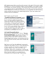
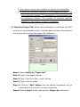
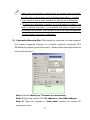
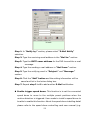
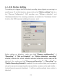
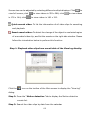
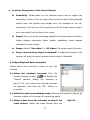
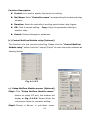
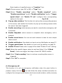
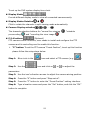
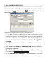
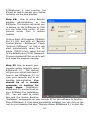
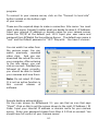
4-1-2-3. Motion Setting
This setting is to trigger the DVR to start recording when objects are moving in a
specific area. To set this function, please click on the ―M otion settin g ‖ tab from
the “C am era C onfig uration ”. D V R provides u ser “S oftw are detection ” and
“H ard w are detection” for secu rity p rotection, to enable the “H ard w are diction”
function, the DVR requires installing the sensor card.
Before setting up detection, make sure that ―C am era con fig u ration ‖ 
―R ecordin g‖  ―S et u p S ch ed u le‖ has ―M otion detection recordin g‖
selected, and also the correct schedule selected, otherwise motion may not be
detected. Also, make sure that ―C am era con fig u ration ‖  ―R ecordin g‖ has
―En able R ecordin g S ch ed u le ” enabled . You can confirm th at you ’ve p roperly
set up the camera by inspecting the camera button number on the right toolbar –
it should now be greenish (waiting). It will turn red (recording) when motion is
detected.
58
1.) Software detection -- Selecting software detection will save you the cost of
installing extra devices, but will cause false alarms more easily.
2.) Sensitivity of motion detection – You can adjust the sensitivity of the
motion detection. Slide the bar to the right to increase sensitivity or left to
decrease sensitivity.
The value for sensitivity should be based on unavoidable movement in the
area of the camera. For example, if you have a fan blowing, a banner may
be moving slightly.
Adjusting the sensitivity properly will filter out this
movement.
3.) Set up area – Use this button to set specific areas for motion detection.

To add a specific area for detection, please follow the setting steps
below:
Step1: Press mouse left button and hold to move mouse for selecting a
specific area on the screen.
Step2: Press ―A d d area‖ button to add the area diction.
Step3: To set more another area, please repeat the step1 to step2.
59
Step4: Press the ―O K ‖ button to complete the areas setting.

To delete a setting detection area , please follow the setting steps
below:
Step1: Select a setting detection area by mouse right button.
Step2: Press the “Delete area” to delete.
Step3: To delete another setting detection area, please repeat step1 to
step2.
Step4: Press the ―O K ‖ button to complete the areas setting.
If enable the “M otion detection recording ” in the “S et up sched ule” section
of the “R ecording ” tap, b ut not specific a detection area in the “S et up area”
section of the “M otion setting ” tab, the full area w ill be th e default settin g.
 Hardware detection (Optional)
You can also select hard w are detection . A fter en abling “Hardware
detection”, select the specific sensor to use from available port. You need to
con nect the sen sor device to the port of “Sensor in” of “N etC om m od u le‖.
When the sensor is triggered, it will start to record and trigger the port of
relay output.

Tolerance – This function is to prevent false alarms by defining
acceptable movement. If the tolerance is set 2, video screen must change
continuously 3 times before the DVR recording.

Post recording – This function sets the time to continue recording after
motion is no longer detected; the video will be saved as a file. If the time
between one motion detection period and a new motion detection period
is less than the value in this field, the two recordings will be combined. It
will reduce the motion detection video file and notification.

Pre-alarm
60
If u ser ru ns recording b y m otion detection and enable “Pre-alarm ‖, the
system can record videos at last 1-30 seconds (Base on the recording
rate) before event trigger base on the system RAM buffer.
4-1-2-4. Video Loss
This function is to trigger the DVR to send a notification when video losses occur.
Please click on the ―V id eo Loss‖ tab and follow the instructions below for the
setting.

Enable sound alarm –To set an audio warning when the video loss occurs.

Enable notification -- Each camera can have its own unique notification,
and you can set up different ways to notify someone. Please refer to page
41 to 44 for the notification setting.

Trigger speed dome – This function is to set the connected speed dome to
move to the multiple preset positions when the video loss occur. Please refer
to page 4 5 to 4 6 for the detail of the “S elect position ” section setting .
61

Trigger relays – To trigger relays when the video loss occur.
4-1-2-5.POS & FingerKey (Optional)
This function provides POS and Fingerkey text to display on the screen for specific
video clip playback searching easily. After completing the hardware installation of
PO S text inserter system and the Fingerkey, please p ress “PO S & Fingerkey” tab
from the top of the “C am era con fig uration ” setting and follow the instructions
below to setup the program.

Font: Click
icon to specify the font size of text to past on the video
clips.
 Delete: Click
icon to delete the text on the.
 POS text data show on: Enable/disable Monitor, Video clips and
Remote to display the POS text on the connected monitor, video clips or
remote PC.
62

Setup POS & Fingerkey connection
 Printer model: Select printer model, which is to be used with your POS
system.
 Setup keywords: Allows you to setup Keywords for searching video clips.
Please type in the specific keywords in 1 to
10 column, and press “OK” button for
saving the setting.
63
 Setup the printer command code: The DVR is able to process certain
functions after receiving the printer command code, such as recording with
the event of opening cash draw.
 Fingerkey: To select a connected fingerprint access controller to capture
the Fingerkey access record text on the video clips.
 Text position: To change the display position of text by working on the
column position.
 Insert POS text: Determine the status of inserted text.
 Keep text records: Setup the text keeping period.
 Enable video recording when transaction starts: This enables video
recording once the sale starts and specifies the time period of video
recording once the sale stops
 Clear text over screen when transaction ends: This would clear/clean
up the text over the screen after the specified time period when sale stops.
64
4-1-3. EzSyncPlayback
Clicking the (
(
) icon on th e tool bar and select the “EzS yn cPlayb ack”
) to display the “E zS yncPlayback” interface for searchin g video
clips.
 EzSyncPlayback Overview
1
2
10
3
9
4
8
7

6
5
EzSyncPlayback Function Description:
1. Split screen display modes section: To select the split screen display
mode
2. Camera selection of the video clips: To select the playback cameras of
65
the selected video clips folder.
3. The video clips deletion: To delete the video clips from the hard drive.
4. Video streams searching calendar: Provide user to search the video
streams of the video clips by date, the red color of the dates contain
recorded video data.
5. Cameras switch: C lip the “U p ” an d “D ow n ” b uttons to display the video
stream of the cameras.
6. Playback toolbar: Provide powerful functions for user to view and search
the playback video clips.
7. Video stream searching bar:

0~23 (Hours) selections: To search the video stream data by hours.

White/Gray color video stream blocks: White color block indicates
empty data, and gray color block indicates the block with video data.

0~60 (Min) dragging bar: To search the video steam data by
minutes.
8. Playback speed selection: Provide user to select the playback speeds to
searching easily.
9. Video stream information: To display the selected video steam
information.
10. Display screen: To display the video.

EzSyncPlayback Toolbar Description:
Play – Click this icon to play back videos.
Pause – Click this icon once to pause videos.
Play backward – Click to play video stream backward.
Stop – Click this icon to stop videos.
Previous frame – Jump to previous frame.
Next frame – Jump to next frame.
First frame – Jump to the first frame of video clip.
66
Last frame – Jump to the last frame of video clip.
Repeat playback – Click this icon once have the videos play back on
repeat. Click once more to cancel repeat.
Zoom in – Click this icon to zoom in.
Zoom out – Click this icon to zoom out.
Original – Click this icon to go back original video size.
Video copy – This button will copy current video clip to a specific location
for archiving . U ser could enable/disable “Copy audio data”.
Delete video – Erase video play back file.
Navigation bar – This displays the current position of the video clip and
allows users to move to different points within the clip. Left moves
backward, right moves forward.
Snapshot – Click this icon to capture the video screen as a BMP or JPEG
file.
Repeat – Click this icon once have the videos of all camera play back on
repeat. Click once more to cancel repeat.
Resize – Click this icon to resize clip.
Next video – Jumps to the next video.
Previous video – Jumps to the previous video.
Decrease frame rate – Decreases the frame rate.
Normal frame rate – Adjusts frame rate back to normal.
Increase frame rate – Increases the frame rate.
67
Screen size can be adjusted by selecting different multiple displays. Click
view full screen; click
in 176 x 144; click
to view videos in 352 x 288; click
to
to view videos
to view videos in 160 x 120.
Quick search video: To list the information of all video clips for searching
and playback.
Smart search video: To detect the change of the object in a selected region
of a recorded video clip, and list the events on the right side window. Please
follow the introduction below to perform this function:
Step 1: Playback video clips from event table of the View log directly:
Click the
icon on the toolbar of the M ain screen to display the “V iew log”
dialog.
Step 2: Press the “Motion detection “tab to display th e M otion detection
events list.
Step 3: Search the video clips by date from the calendar.
68
Step 4: Double click the desired video clips from the event list to display the
playback interface.
Step 5: Press the
icon on the playb ack toolbar to display the “S m art
search” interface (as show in g in Fig 4-1-3.1).
Step 6: Press and hold the mouse left button to select a specific searching area.
Step 7: Click the ―A dd area‖ button to add a highlighted region. User can use
the same way to add more areas.
Step 8: A djust the “ Sensitivity “, the“ Speed “and the“ Range “ fu nction, and
click the “ Search “ b utton to start the sm art search function.
Step 9: As showing in Fig 4-1-3.2, the system will display all detected object
change events on the rights list window, and use can select an event to
playback.
Fig 4-1-3.1
Fig 4-1-3.2
69

Function Description of the Smart Search:

Sensitivity: Please base on the selected region size to adjust the
sensitivity function. If set too high of the sensitivity with the big selected
search area, the system may display very tiny changed on the list,
oppositely, if set too low of the sensitivity with the small search region,
user may easily find nothing in the result.

Speed: User can set the searching speed for the smart search function,
higher degree represents faster speed; oppositely, lower degree
represents slower speed.

Range: S elect” One video “or “All videos “for sm art search fu n ction .

Stop to search when object is detected: If enable this function, the
system will stop the search process when object is detected.
 EzSyncPlayback Basic Operation
Please follow the instruction below to use this
function:
1.) Select the playback cameras: Click the
camera selection button (
“S earch
cam era”
dialog
) to display the
(A s
show ing
in
Fig4-1-3.4), then select the desired cameras
for playb ack, and click the “O K ” b utton to
complete.
2.) Select the split screen display mode: Select a split screen to display all
cameras videos on the screen for searching easily.
3.) Select a date from the calendar to search the
video stream: Select the video stream from the
70
Fig4-1-3.4
calendar by the order of year, month and date.
4.) Select display camera: C lick the “U p ” and “D ow n” button to display the
desired cam eras’ video stream .
5.) Click a desired gray color video stream block to play: Click a desired
gray color video stream block, and click the play icon to view.
4-1-4. Playback Video Clips
Clicking the (
(
) icon on th e tool bar and select the “Playback V ideo C lip s”
) to display the “S earch video clip s” interface for search ing video
clips.
Follow the steps below to play back videos:
Step 1: Click
in the middle of right side to search for videos in database.
And you will see below window.
Step 2: Select the camera. To play multiple videos, select ―0 0 C am era 0 0 ‖.
Step 3: D ecide w hich recording w ay w ill be searched by “Options”.
Step 4: Select the recording period, then click search to find the clips among
the selected time.
71
 Follow the steps below to remove a video from your archive:
Step 1: Click
on right screen to search for videos.
Step 2: D ecide w hich recording w ay for deletion b y “Options”.
Step 3: Select the videos that need to be removed.
Step 4: Select camera and time of the archived video.
Step 5: Click ―D elete‖.
 Play back Archived Videos:
At the playback screen, you can play back videos. Camera number, camera
location, time recorded, storage space, etc. will be displayed on the screen.
Double click on any video screen to enlarge a single video. Move the mouse to
any video screen to show video tool bar and information of single video (see
below picture). Double click again to restore the previous viewing screen.
72
Please refer to the chapter 3-2-3-3 EzSyncPlayback for detail of the
Playback toolbar functions.
4-1-5. Network Configuration

Do not setup the Identify Server. This section of the software is
not functional with this version.

Set up E-Map
Enter the information for the DVR and insert a map to arrange the location of
the device.
Once these devices are triggered, the information can be
transferred to a remote PC via modem or internet. The triggered devices will
be flashed on the map at the same time. Follow the instructions below to
73
complete the setup.
1.)C lick” Set up E-Map “icon and below picture will be shown.
2.)Enter the DVR name into ―S ite n am e ―.
3.)Click “ Map source “ icon to b rowse the map file from DVR folder and
then click “Update” icon after you find out the M ap file. (The m ap file
can be a BMP or JPG file.)
4.)Enter the data into “ Contact “, “ Phone “, “ Address “ and “ Note
“ tab. It w ill show the D V R inform ation on the rem ote client PC w hen
connecting.
5.)Select the available devices for decorating on the DVR map from
“Select device“.
6.)Move to the device and then click and drag down to the suitable location
with the left mouse key. Repeat this process for another device.
7.)Click ―S ave ―button to complete the setting.

Remote user currently connected
User can simply click this button to view the remote currently connected
u sers’ in form ation .
74
4-1-6. System Configuration/EzTools

System Configuration
Click the
b utton , the system
w ill display “S ystem
con fig uration ” and “E zTools” selections. To set up the DVR
system con fig uration , sim ply click th e “S ystem con fig uration ” and the system
will display as below.

Function Description:
Enable watch dog timer Enable this function will reboot DVR and be back to
original setting if system shutdown caused by hardware or software problem.
Auto run surveillance system Enable this function will start EZWatch Pro
when system starts up.
Logout when window is minimized Enabling this function will logout
75
EZWatch Pro when the software is minimized and pressing the “ ESC “ key on
the keyboard will hide the tool bar of the EZWatch Pro program.
Pop-up event notification Enable this function will pop-up the event
notification message on the screen and the camera or sensor will be flashed on
the eMap when the device is triggered.
Fit video display to window will enlarge the space taken by the video display
window.
Stop sound alarm when stop trigger Enable this function, the sound alarm
will stop when trigger stops.
Minimize window when start program To minimize the video window when
enable EZWatch Pro Surveillance Server program.
Video file closed and renew when playback Enable this function, the video
file w illclose and renew a new one autom atically w hen you click “Playback “icon.
You can playback the current video file without waiting till the file close. Enable
this function, it will cause the length of video file not same as your setting on
some video files.
Exit option To select PC status after exiting EZWatch Pro. Press the arrow
buttons to switch among “Exit program”, “ Turn off “, “ Log off “or “ Restart
“. For example: S elect “Tu rn off‖, the system will automatically shutdown after
exiting EZWatch Pro.
Auto login Enable this function will automatically login by user name and
password saved in the system when you reboot.
Section of the NetCom Module:
Model S elect “3213USB or NC-320AM-I“ type for control the PTZ cam era, D /I
and D/O device. Base on which kind PTZ controller cards you plug into your DVR.
Checksum Enable Checksum or not will depend on the type of Speed dome
camera. Please refer to the manual of Speed dome camera.
76
Com Port You m u st select “Auto” from the draw m en u of ―C om P ort ―icon
when you want to enable the function of Netcom module.
Baud rate You need to select a correct Baud rate if you want to control the
Speed dome camera or P/T/Z camera from Witness DVR board (Default setting
is 9600 bps).
Dip switch of NC-3213USB Control Board:
The dip switch for the bound rate setting, please refer to the table as below:
Baud
rate
240 480 960 192
0
0
0
00
Switch
S1
↓
↑
↑
↓
S2
↑
↓
↑
↓
1.) You must select 9600 baud rate, enable Checksum icon and select
“ Pelco P “ or “ FastC am III “ or “ S D C I-2 2 0 “, w hen you u se I-V iew ’s
FastCam Speed dome camera series.
2.) The ID 0 of Pelco “ P “ is sam e as C am era 1 of D V R , ID 1 same as
camera 2.
Select Modem For EZModem user or using Phone/Pager notify function should
select which modem will be used and en able “M on itor‖ below to communicate
with DVR.
If user’s m odem
and fax sh are one telep hone line, user m u st
disable ”m on itor‖ when no more connection required otherwise modem will
occupy phone line always.
1.) You can select “N on e” to leave m odem open for oth er com m u nication
software or voice calls.
2.) You m ust select w hich m odem w ill be used and enable “M onitor” for
77
EZModem user and Phone/Pager notify functions.
3.) Please contact to your local dealer for asking the model of Modem.
Screen rotation time regulates the time period of camera rotation by clicking
on the main screen. Click on the icon again to disable the rotation function.
(Default setting is 5 seconds)
Assign camera rotation To rotate the sequence of the assigned cameras,
which you want to show on the screen. There are two kinds video out rotation;
one is “Split video out “and the other ―S in gle vid eo ou t ―. Follow the
instructions as below to set up the video rotation:
Assign camera rotation (Split video out) (For CP-1320RD and 1160RD
Deluxe only)
1.)
Select the rotation way from the ―S plitter‖ of drop down menu as the
window above.
2.)
Choose the camera that will be first image on split screen at the drop down
menu ―C am era‖.
3.)
Enter number into ―S tay tim e‖ tag.
4.)
Click ―A d d ‖ icon to save the rotation image.
5.)
Repeat 1 to 4 for adding other rotation split videos.
6.)
Click ―O K ‖ to complete the setting.
The rotation camera for 9 split screen, which can select 1-9 or 8-16 camera
for 9 split screen display only.
Assign TV out rotation (Single video out)
1.) Click
icon and then sw itch to the setting of” TV out rotation‖
mode.
78
2.) Choose the camera, which you want to display on the TV at the drop
down menu ―C am era ―.
3.) Enter number into ―S tay tim e‖ tag.
4.) Click ―A d d‖ icon to save the rotation image.
5.) Repeat 1 to 4 for adding other rotation videos.
6.) Click ―O K ‖ to complete the setting.
Enable restart system provide user to restarts your DVR at a set time. Using
this function stabilizes the program after a long period of usage.
Visible motion area provide user to view the setting motion detection area.
This function is only for the model of CP-1320RD and 1160RD Deluxe. To enable
this function, user need to set up the motion setting and enable the schedule
recording of motion detection in the camera configuration section.
 EzTools
This function is to provide user selection the DVR main program tools without
minimize the current surveillance sever program. To enter this selection, please
click the
icon, and select the EzTools selection, then the system will display
as below
79
4-1-7. Setup Privileges
Click
icon to enter ―S et u p privileges‖ interface for creating and
modifying usernames and passwords. Users will have access to different only
certain levels.

Supervisor name and password
The default supervisor name and password is listed below:
Username: root
Password: 123
Please follow the steps below to modify the su p ervisor’s n am e an d
password:
1.) Enter new supervisor name and your chosen password.
2.) Press ―S elect all‖ (only for supervisor) and also click “>>” to authorize all
cameras.
3.) After completing the steps above, click ―A d d‖ to finish setup. Click ―Exit‖ to
leave ―S et u p privileges‖
80
Please rem em ber rem oving the default supervisor “root”, otherw ise there
will be two supervisors.

Set privilege for additional users
1.)
Enter username and password, enter password again for
confirmation.
2.)
Select privileges.
3.)
Select cameras and authorize use by clicking on ―A u th orize‖.
4.)
After completing the above steps, click ―A d d ‖ to finish user setup.
5.)
To add another user, please repeat 1 to 4 steps.
1.If the supervisors password or username is lost, EZWatch Pro must be
reinstalled. All previous settings will be lost but saved videos will not be
erased.
2 Passwords must consist of 0-9 and a-z or A-Z.
3.The password is case sensitive. (PaSsWoRd is not the same as password)

Remove/modify user privileges
1.)
Select the user in the username list.
2.)
Click ―D elete‖ to remove user or double-click on the username to
modify user privileges.
4-1-8. View Log
The EZWatch Pro will classify the logs by date and different events types. To
check the system logs simply click the
window as showing below.
81
icon and the system will display the

Evens types

Log list window
 Function Description:
Save log button: To save the log list as a file.
Clear log button: To clear current log list.
Exit button: To exit this interface.
Evens types: User can simply click each type tabs to find a specific even
type’s log list easily.
Log list window: To list each type logs.
4-1-9. Setup I/O
Click
on tool bar to setup I/O configuration and parameters. Users will be able
to Setup relay, Control relay, Setup sensor, Setup Emergency call etc.
(Fig.4-1-9.1)
If you plug-in the NC-3213USB or NC-320AM-I NetCom module successfully,
all fu nctions icon s w ill be en abled . O therw ise only “setup em ergency call
“and “S et up Fingerp rint “w ill be enabled .
82
This fun ction can also be
checked if the NC-3213USB or NC-320AM-I NetCom module has been set up
successfully.
a)
b)
c)
d)
e)
Fig. 4-1-9.1 Setup I/O port
a.) Setup relay (Optional)
The setup relay option is available when the additional relay board for the
NetCom module is installed.
Fig. 4-1-9.2 Setup relay
83
Function Description:
 Control: You need to specify the device for setting.
 No/Name: E nter “Controller name” corresponding to the desired relay
number.
 Duration: E nter the controller’s w orking period w hen relay trigger.
 OK: Click to accept setting. Copy: Copy the parameter setting to
another relay.
 Cancel: Discard changes in parameter.
b.) Control NetCom Module relay (Optional)
This function is to test remote controlling. Please click the ―C on trol NetCom
M od u le relay‖ b utton from the “setup I/O port” to enter the setup interface as
showing below.
Fig. 4-1-9.3
c.) Setup NetCom Module sensor (Optional)
Step1. Click ―S etu p N etC om M od u le sen sor‖
button on setup I/O port, the window will
display as Fig. 4-1-9.4. Please follow the
instructions below to complete setting.
Step2. Choose a Sensor in pull-down menu.
84
Enter location of specified sensor in ―Location ‖ box.
Step3. Choose sensor type (NC or NO) in ―Typ e‖ box.
Step4. Select ―En able recordin g ‖ and/or ―En able sn ap sh ot‖ and/or
―En able sou n d alarm ‖ and/or ―En able n otification ‖ and/or “Trigger
speed dome” and “Enable TV out” con fig ure their corresponding
options to the right.

Fig. 4-1-9.4
Pop up video window: This function is to set up the corresponding camera
of the sensor, and enable this function to pop up the setting camera while
the sensor has been triggered.

Enable recording: select camera you want to record when emergency call
is pressed.

Enable Snapshot: select camera to snapshot when emergency call is
pressed.

Enable sound alarm: You can set each camera to have its own unique
alarm sound.

Enable notification: See details on how to set up Notification on page 37.

Trigger speed dome: See details on how to set up position on page 41.

Enable TV out: Please refer to page 4 4 for detail “E nable TV out” setting .
Step5. Select the specific trigger relays to use from Relay 01 to 06(Back
Panel). It also can trigger the relays of each NC-180AZ module.
Step6. E n ter” Post recording” tim e to contin ue recording after sen sor is
triggered.
Step7. C lick “O K ‖ to complete.
d.) Emergency call
This function is to set up emergency notification when the panic button is
pushed, simply click the
icon and follow the setup interface instruction to
configure the emergency call feature which are sound an alarm, notify someone,
85
start recording or show live video feeds on connected TV sets.
e.) Fingerprint Access Control
While user connected the fingerprint access
controller, user can simply click the
icon.
For detail of the Fingerprint Access Control,
please
refer
to
the
fingerprint
access
controller user manual.
4-1-10. Storage Device Configuration
This function is to set up system configured storage device and video saving
compression rate.
 Storage device configuration interface description:
86
Set up storage device: This button is to
enable
the
system
configured
video
storage. To enable the configured device,
sim ply check the device and click the “O K ”
button to complete. Selects your video
storage location (C:\, D:\, etc). Since C:\
usually stores O.S., it is best to store the video files on an alternative hard drive
if one is available.
Add/remove storage device: This function is to detect the new storage device,
but the DVR system need to be restart. This button must be clicked after a HDD
drive is removed or added to your system. Otherwise, the program may not find
playback video files. Clicking this will close your application, please remember to
restart it.
Please perform this function if you find that the playback function is working
abnormally. Running this function could repair video clip and rebuild the
Database of video clips and reindex the database.
Setup
Video
Compression:
This
section provides you with the ability to
control video recording compression and
quality.
You can control the video
quality with the compression control
slider. Move the slider to the right for a
crisper picture or move the slider to left
for smoother video playback.
Note:
The CPU will use more power when the
slider is set higher. The data rate slider bar controls the amount of data that is
87
recorded to each video clip. The further left the slider, the fewer images that it will
record. If the setting is set lower, you can have more data or video time recorded
and visa versa.
Space to erase each time: This section is to set up the DVR system erasing the
image storage space size each time.
Record to hard disk & Frequency of save to disk When you enable ―R ecord
to h ard disk‖, your video clips will be saved to hard disk every few minutes
automatically. For example, if Frequency is “5 minutes”, video clip s w ill be
saved every 5 minutes. You can choose from anywhere between 5 and 30
minutes. Using this option can minimize video clip loss under abnormal conditions,
such as a power outage. If you enable this, it is recommended that you add a fan
for the hard disk because of the additional heat that will be generated. If you
disable this function, video clips will be saved in memory and saved
to disk based on your settings in Camera configuration  Recording
 File. However, if the system shuts down abnormally, all clips not
saved to disk will be lost.
Start to erase when free space less than Will start to free space
on your hard disk when only a certain amount of space is left on
your hard disk. Older files are erased first.
Space to erase each time This specifies the amount of disk space
to free when the above limit is reached. Older files are erased first.
As an example, if 1200 MB is entered, 1200MB will be erased when
the limit is reached.
4-1-11. Video Control Panel
 Clock Setting
88
To set up the DVR system display time clock.
 Display Modes
Provide different display mode to view all connected cameras easily.
 Display Modes Rotation

Click to rotate the channels in split viewing mode automatically.
 Camera Display selection
,
,
…
The ch ann els selection b uttons for “norm al live view ing
prerecording
” and “recordin g the view im age
 P S A buttons
(Optional)
”, “sched ule
”
PTZ camera control functions, user needs to install and configure the PTZ
camera and its controlling card to enable this function.
 ―P ‖ b u tton : To set the PTZ camera “Preset Position ”, to set up this fu n ction
please follow the setup steps below.
Step 1: Blue circle in the
Step 2: Use the
icon and select a PTZ camera (e.g.
icon and click on
or
).
to adjust the
parameters.
Step 3: U se the icon ’s directio n arrows to adjust the camera aiming position.
Step 4: Press the “A” b utton and press “S top sw ivel”.
Step 5: Press th e “P” b utton to enter the “Preset Position” setting interface.
Step 6: Type a location nam e and p ress the “S et” b utton, and click the “O K ”
button to complete.
89
―G oto‖ b u tton : To test the setting PTZ camera if aim to the preset position.
 ―S ‖ b u tton : To set the speed for this camera pan, tilt, and zoom.
 ―A ‖ b u tton : To adjust the PTZ cam era “A uto scan” m odes.
 TV out
Click this icon to rotate videos or pop-up the on TV. (For single video out) You
can choose which camera(s) and how many seconds will show on the TV.
 E-Map
Click this icon to show the information and map of DVR. When the sensor and
h
camera is triggered that the icon will be flashed and video will pop up the TV out.
If you use the dual monitor to display, the map will be shown on another monitor
automatically.
 Relay
 Click this icon to set up I/O sensor of NC-180AZ Receiver module.
90
4-2. Back up system-EzBackup
This chapter will show how to back up video clips to another storage device from
your saved database.
 Follow the steps below to back up videos
1. Click
in the top of left side to search for videos in database. And you will
see the window below.
2. Select the camera. To play multiple videos, select ―0 0 C am era 0 0 ‖.
3. D ecide w hich recording w ay w ill be searched b y “Options”.
4. Select the recording period time and date. Click search to find the clips
among the
selected time, and the system will display the window as
below.
91
5. Select video file, which you would like to have by manual. Or you also can click
to select /remove selection all video file.
6. Click
to back up video clips to another HDD drive. Or you also can click
icon and you will see below window to back the video clips into
CD-RW/DVD+-RW. Click the ―B u rn N ow “b utton for start backup video files.
These backup video clips can be searched by I-V iew ’s EzPlayback p rogram .
7. Click
to complete backup.
 Video tool bar on backup screen
Search – Click this icon to search video files.
Select – Click this icon to select/remove all video clips to back up video clips.
Create backup shortcut – Click this icon to paste the video clips which has
been selected to the other storage devices; such as CD-RW/DVD+-RW or
HDD.
Back up video clips – Click this icon to back up video clips to Hard Disk.
CD Burning – Click this icon to back up video clips CD-RW or DVD+-RW.
About - Press to see the program version.
Exit – Exit the video backup setting window.
92
4-3. Web Browse Server – EzWebServer
This function is to provide user for remote monitoring with IE browser via
internet. Please follow the instruction below to set up this function.

Setup in local host DVR sever:
Fig. 4-3.1 EzWebServer
Step 1: Please click the “W eb B row ser S ever – E zW ebS erver” button to enable
this function.
Step 2: Click ―En able au to ru n
system ‖ and ―H ide w in d ow ‖ to
automatically enable the EzWebServer when start the EZWatch Pro system
every times.
Step 3: Please click the “S et up E zW ebS erver” button and fill out the “W eb IP
ad dress” section . For detail about the fix IP add ress, please contact you r IS P
provider.
93
Fig.4-3.2 C lick the “S et up E zW ebServer” to display “Set up EzWebServer”
Step 4: Please click the “W eb File” button and fill out th e in form ation in each
section of the “D em o.htm ” interface, then click the “G enerator” b utton to
complete the settings.
Fig. 4-3.3 “Demo.htm” setting interface
 ―D em o.h tm ‖ S etu p in terface section s descrip tion :
 Connection Type: To S elect use “IP A dd ress” con nection or “ID C ode” (For
Dynamic IP address connection) connection.
 DVR IP Address: If user selects “IP A dd ress” con nection type, please fill
the DVR IP address in this section.
 ID Code: If user selects “ID C ode” connection type, please fillth e ID code in
this section
 Port number: Please type the port number for remote connection.
Please make sure the setting connection port is not used by PC program
commonly, or the connection may be collided with other PC application
program.
94
 Auto connection: E nable this fun ction and type in the “U sernam e” and
“passw ord to allow rem ote PC to set up rem o te connecting this DVR
automatically.

Remote client PC setup:
Step 1: Click IE Browse from the Remote client PC, and then enter the IP
address of Local DVR Server.
Step 2: Please allow the ActiveX program to install on your PC when the
ActiveX pop-up, and the screen in IE browser will display as below.
Step 3: Click
icon from the right side control panel to connect the Local
D V R S erver, and the screen w ill display the “C on nect to local site” setting
interface.
95
Step 4: S im ply give a nam e in “S ite nam e” and type in the D V R IP add ress or ID
code, (TC P/IP) port nu m ber, Login “U ser nam e” and “Passw ord ’, then p ress the
“C on nect” b utton to start the con nection.
96

Browser Viewing Tools Function Description:

Display mode selections

Sites Rotation
The channel selection
buttons.
Remote DVR connection
setup
To disconnect the connection
Select Audio enable and the
PTZ camera control
To enlarge the selected
channel in split display
mode
To select channels in Full
size display mode
4-4. LAN Play Back Video Clips – EzLanPlayback
This chapter introduces how to use the EzLanPlayback program via the Local Area
Network (LAN) connection. Before start to use EzLanPlayback program, please
make sure that the file folder (e.g. ClipPro folder) of the EZWatch Pro is shared to
network users, and follow the instruction below to start.
97
Step 1: Please go to the path: Windows ―S tart‖ m en u  ―P rogram s‖ 
EZWatch Pro, and click the ―LA N play back video – EzLan P layb ack‖ to start
the program as showing below
 Play video clips from a default folder:
Step 2: To use default localvideo clips file folder, sim ply click the “
” icon on
the right side control panel, and the system will display a video clips searching
dialog as showing below.
98
Step 3: Select the desired camera and specific date, then click the ―S earch ‖
button to search the video clips.
Step 4: The system will automatically playback if the program finds the video
clip s, or it w ill display a m essage of “N o V ideo C lips”.
 Play
video
clips
from
the
local
specific folders:
Step5: To select a specific local folder of the
video clip s, sim ply u ncheck th e “U se default”
box and press the
icon on the right side
control panel and the system will display the
“S earch video clip s” dialog as show ing
below.
Fig 4-4.1 Search video clips
Step6: Click the
icon to select a specific video clips folder for playback,
and p ress the “A dd” button to add the selected folder path for video clips
searching list, and repeat this step to add more video clips folder path on the
searching list. Press the ―R e-search video clip s‖ button to finish the adding.
99
Step7: C lick the “
” icon and repeat the Step3 and Step4 above again to
play the specific local folder video clips.
 Play video clips from the network sharing folders:
Step8: To play the video clips from the remote network sharing hard drive
folder , please click the “
” icon to display the netw ork h ard d rive setting
dialog, follow the dialog instruction and type the specific directory of the network
sharing folder to add the path in the searching list. To add more network sharing
folder, please repeat this step again. Press the ―R e-search video clip s‖ button
to finish the adding
Step9: C lick the “
” icon and repeat the Step3 and Step4 above again to
play the network sharing folder video clips.
4-5. Play Back Video Clips – EzPlayback
This function is for user to play back video clips in fast and simple way. Please go
to the path: Windows ―S tart‖ m en u  ―P rogram s‖  EZWatch Pro, and click
the ―P lay back video clips – EzP layb ack‖ selection to start the program
100

To open a video clips and play:
1.)
Press the “file” fun ction from the program up per left side, and click the
“O pen ” selection .
2.)
The program will display a file selection dialog, then select a video clips
file and press the “O K ” b utton to finish the selection .
3.)
The program main screen will display an initial image of the selected
video clip, sim ply p ress the “

” icon to start the playing .
EzPlayback Control Panel Function Description :
Play – Click this icon to play back videos.
Pause – Click this icon once to pause videos.
Play backward – Click to play video stream backward.
Stop – Click this icon to stop videos.
Previous frame – Jump to previous frame.
Next frame – Jump to next frame.
First frame – Jump to the first frame of video clip.
Last frame – Jump to the last frame of video clip.
Zoom in – Click this icon to zoom in.
Zoom out – Click this icon to zoom out.
Original – Click this icon to go back original video size.
Navigation bar – This displays the current position of the video clip and
allows users to move to different points within the clip. Left moves
backward, right moves forward.
Snapshot – Click this icon to capture the video screen as a BMP or JPEG
file.
Resize – Click this icon to resize clip.
Decrease frame rate – Decreases the frame rate.
101
Normal frame rate – Adjusts frame rate back to normal.
Increase frame rate – Increases the frame rate.
Smart search video: To detect the change of the object in a selected region
of a recorded video clip, and list the events on the right side window. Please
refer to the page 53 to page 55 of this manual for detail function description.
4-6. Text insert Playback – EzTextPlayback
To enable this function, user need to install the POS system with the PC, Please
go to the path: Windows ―S tart‖ m en u  ―P rogram s‖  EZWatch Pro, and
click the ―P O S P layb ack— EzP osP layback‖ icon. Please refer to the PTI-100
user manual for detail POS system hardware installation, system configuration
and functions usage.
Fig.4-6.1 POS Playback
interface
4-7. Remote Control Server– EzRServer
This fu nction is to allow user rem ote connecting the D V R b y the “EZNetwork” PC
program. To enable this function, simply click the
icon from the path of the
Windows ―S tart‖ m en u  ―P rog ram s‖  EZWatch Pro, and the system will
display the ―EzR S ever‖ setting interface as showing below.
102
 EzRSever Setting Description:
 Autorun EzRSever: Check to enable
the EZWatch Pro to automatically run
the EzRSever when system starts.
 (TCP/IP) Port: To set the connection
port for remote client PC connecting.
 Password: To set the connecting
password.
 Disconnect all clients button: To
disconnect all remote connection.
 OK button: To enable the EzRSever function and complete the setting.
 Exit button: To disable the EzRSever function and exit without the setting.
4-8. Two Way Communication – EzSTalk
This chapter will show how to have the real-time audio from designated locations
is simultaneously transmitted to both the control center and designated DVR
sites.
Fig 4-8.1
Fig 4-8.2
103
 Follow the steps below to setup audio communication:
From EZWatch Pro or local site:
Step1: Click
icon from the Windows ―S tart‖ m en u  ―P rogram s‖ 
EZWatch Pro, and the system will display as Fig 4-8.1.
Step2: Enable ―A u to ru n system “icon , the p rogram w ill be en abled w hen
you turn on the PC.
Step3: Enter your ―P assw ord‖ for remote client connection.
Step4: Adjust the audio volume of Listen and talk to suit your request, if it is
necessary.
On Remote Client PC site
Step 1: Once user has finished installing the EZNetwork software, go to the
path of Windows ―S tart‖ menu  ―P rog ram s‖  ―EZNetwork‖, and then
clicking on the ―Tw o w ay com m u n ication – EZ C Talk‖ icon, and the
system will display as Fig 4-8.2.
Step 2: Enter the ―IP add ress‖ or ―ID C ode‖ and ―P assw ord‖ of the DVR
board site setting.
Step 3: The n um ber of “TCP/IP Port” m ust be m atched betw een
EZNetwork and EZWatch Pro.
Step 4: Choose the ―A u dio sam ple rate‖. Choosing a 16K audio rate will
give a better audio quality, but also take up more bandwidth. Oppositely,
choosing an 8K rate will give a worse quality and less bandwidth.
Step 5: In the ―C om m u n ication ‖ section. Check the ―Talk‖ and ―Listen ‖
function box for two way communications.
Step 6: Adjust the audio volume of Listen and Talk to suit your request, if it
is necessary.
Step 7: Press the ―C on n ect‖ button to start the communication process.
104
4-9. Access Control – EzFingerKey
While user has connected to the fingerprint access controller, user can go to the
path of Windows ―S tart‖ m en u  ―P rog ram s‖  EZWatch Pro, and click the
―A ccess C on trol – EzFin g erK ey‖. For detail about the fingerprint access
controller installing, system configuration and the functions usage, please refer
to the fingerprint access controller user manual.
4-10. Uninstalling EZWatch Pro Software and
Device Driver
This chapter describes the removal of the software and device driver.
4-10-1. Uninstalling EZWatch Pro
You can uninstall the EZWatch Pro software by doing the following steps:
105
Step 1: Click ―S tart‖,
―P rog ram s‖,
―EZWatch Pro‖,
and then select
―U n in stall
EZWatch Pro‖.
Step 2: Click ―Y es‖ to start uninstalling ―EZWatch Pro‖.
Step 3: Click ―O K ‖ to complete the removal of the software.
4-10-2. Checking for or Uninstalling the Device Driver
You can uninstall or inspect your device driver by doing the following steps:
106
Step 1. Click ―S tart‖, ―S ettin g s‖ and ―C on trol P an el‖, as Fig. 3-2.1.
Step 2. Double-click on the ―S ystem ‖ icon, as Fig. 3-2.2.
Fig. 3-2.1
Fig. 3-2.2
Step 3. Select the ―D evice M an ager‖ tab.
Step 4. As Fig.3-2.3, select ―S ou n d, video an d g am e con trollers‖, where
you will find device driver. The detail driver information, please refer to
the Table 3-1 to Table 3-8
1. If you have more than one Video Server Card, please choose the correct
driver shown on Table 3-1 (For CP-1400AS XP), Table 3-2 (For
CP-1408/1416ASE XP), Table 3-3 (For CP-3408/3416ASE XP), Table 3-4
(For CP-1600 and CP-3200RD Deluxe), Table 3-5 (For CP-1404HS XP),
Table 3-6 (For CP-3404HS XP), Table 3-7 (For CP-1160 and CP-1320RD
Deluxe), Table 3-8 (For CP-1908ASE/CP-1916ASE/CP-1932ASE), Table
3-9 (For CP-5404HS/CP-5408ASE/CP-5416ASE).
107
Driver Name
Video Server Card
WitnessXP PCI 0 Device Video Server Capture
WitnessXP PCI 0 Device Audio Server Capture
WitnessXP PCI 1 Device Video Server Capture
WitnessXP PCI 1 Device Audio Server Capture
WitnessXP PCI 2 Device Video Server Capture
WitnessXP PCI 2 Device Audio Server Capture
WitnessXP PCI 3 Device Video Server Capture
WitnessXP PCI 3 Device Audio Server Capture
CP-1400AS XP 0
CP-1400AS XP 1
CP-1400AS XP 2
CP-1400AS XP 3
(Table 3-1)
Driver Name
Video Server Card
WitnessXP PCI0 (1,2,3) Device Video Server Capture
WitnessXP PCI0 (1,2,3) Device Audio Server Capture
CP-1408ASE / CP-1416ASE XP 0
(Total 8 Device Drivers)
WitnessXP PCI4 (5,6,7) Device Video Server Capture
WitnessXP PCI0 (5,6,7) Device Audio Server Capture
CP-1408ASE / CP-1416ASE XP 1
(Total 8 Device Drivers)
(Table 3-2)
Driver Name
Video Server Card
WitnessASE XP Video Device 0 (1, 2, 3)
WitnessASE XP Audio Device 0 (1, 2, 3)
CP-3408ASE / CP-3416ASE XP 0
(Total 8 Device Drivers)
WitnessASE XP Video Device 4 (5, 6, 7)
WitnessASE XP Audio Device 4 (5, 6, 7)
CP-3408ASE / CP-3416ASE XP 1
(Total 8 Device Drivers)
(Table 3-3)
Driver Name
Video Server Card
Witness 1160RD/1320RD Audio Device 0 (1, 2, 3)
CP-1160RD & CP-1320RD Deluxe
(Total 8 Device Drivers)
(Table 3-4)
Driver Name
108
Video Server Card
WitnessHS PCI 0 (1,2,3) Device Video Server Capture
WitnessHS PCI 0 (1,2,3) Device Audio Server Capture
WitnessHS PCI 4 (5,6,7) Device Video Server Capture
WitnessHS PCI 4 (5,6,7) Device Audio Server Capture
WitnessHS PCI 8 (9,A,B) Device Video Server Capture
WitnessHS PCI 8 (9,A,B) Device Audio Server Capture
WitnessHS PCI C (D,E,F) Device Video Server Capture
WitnessHS PCI C (D,E,F) Device Audio Server Capture
CP-1404HS XP 0
(Total 4 Device Drivers)
CP-1404HS XP 1
(Total 4 Device Drivers)
CP-1404HS XP 2
(Total 4 Device Drivers)
CP-1404HS XP 3
(Total 4 Device Drivers)
(Table 3-5)
Driver Name
Witness 3404HS Video Device 0 (1,2,3)
Witness 3404HS Audio Device0 (1,2,3)
Witness 3404HS Video Device 4 (5,6,7)
Witness 3404HS Audio Device 4 (5,6,7)
Witness 3404HS Video Device 8 (9,A,B)
Witness 3404HS Audio Device 8 (9,A,B)
Witness 3404HS Video Device C (D,E,F)
Witness 3404HS Audio Device C (D,E,F)
Video Server Card
CP-3404HS XP 0 (Total 4 drivers)
CP-3404HS XP 1 (Total 4 drivers)
CP-3404HS XP 2 (Total 4 drivers)
CP-3404HS XP 3 (Total 4 drivers)
(Table 3-6)
Driver Name
Video Server Card
Witness 1160RD/1320RD Audio Device 0 (1, 2, 3)
CP-1160RD & CP-1320RD Deluxe
Witness 1160RD/1320RD Audio Device 0 (1, 2, 3)
Witness BTLive Video
Witness BTLive Audio
(Table 3-7)
Driver Name
Video Server Card
Witness 1908/1916/1932 ASE XP Device
CP-1908/1916/1932 ASE XP
(Table 3-8)
Driver Name
Video Server Card
Witness 5404HS/5408ASE/5416ASE XP Device
CP-5404HS8/1916/1932 ASE XP
(Table 3-9)
109
Fig. 3-2.3
Step 5. Removal only, highlights the device you wish to be removed, and then
click ―R em ove‖ to remove the device driver.
Step 6. C lick “Ok” to com plete th e rem oval of the device driver.
Chapter 5 Remote Client PC Software
5-1. How to use the Remote Client program
5-1-1. How to use EZNetwork
Once you have finished installing the softw are, please go to the w indow s “S tart”
menu, and select the ―P rogram s‖, then ―EZNetwork‖ ,and then clicking on the
―R em ote V iew er – EZNetwork‖ icon. The following icons are available:
110

Remote Viewer - EZNetwork: EZNetwork enables you to remotely patrol
your place from any place at any time as long as you have the access to an
Internet.

Uninstall EZNetwork: Removes EZNetwork from your computer.

Two way Communication- EzCTalk – Real-time audio from designated
locations are simultaneously transmitted to both the control center and
designated DVR sites. Please refer to the chapter 4-8 in this manual.

Remote Control- EzRClient: Allows the Remote client to set up the
EZWatch Pro PC from remote site such as operating at the local. The detail
setting please refer to the Chapter 5-1-10 in this manual.
5-1-2. How to use EZModem
Once you have finished installing the software, there are two icons will be
created in the system. You may access them by clicking on the ―S tart‖ button,
the ―P rogram s‖ folder, then ―EZModem‖ and then clicking on the ―R em ote
Viewer - EZModem ‖ icon. The following icons are available:
111
 Remote Viewer - EZModem: EZModem enables you to remotely patrol
your home, office, retail outlet, warehouse, factory, etc. from any place at
any time as long as you have the access to a telephone line.
 Uninstall EZModem: Removes EZModem from your computer.
112
5-1-3. Free View Pro/EZModem Program Operation
Many of the functions in EZNetwork behave similarly or even identically to
those of EZWatch Pro software.
The tool menu bar enables you to use TCP/IP to connect to the Local DVR
Server via Internet or Intranet easily, control the video channels of the Local
DVR Server, display Local DVR Server video channels, save video files, and
configure exactly how you want the program to work.
Before you can do anything, you must login. You cannot access any of the
functions in EZNetwork without logging-in. Begin by pressing
in the upper
right corner and you should see the window below. The initial, factory default
113
u sern am e is “root”, and the initial passw ord is “1 2 3 ”. You should ch ange the
password as soon as possible after your first login. After you login, you can
explore the system through the following buttons.
Connect to local site: Use this to set up a connection to the Local DVR
Server.
Set up site book: The site book allows you to easily keep track of the sites
you connect to. Rather than entering the same information every time you
connect to a site, you can store it in the site book.
Play back video clips: This would allow user to search video clips by site
name and play back one or more video files of remote client PC from saved
database.
System configuration: Press this to set system configuration.
Set up privileges: Use for setting user privileges.
View log: Press this to see the log-in/logout record and alert table.
Storage device configuration: To configure storage settings.
Remote Control: Allows the remote client user to set up the DSecu series
DVR syetem.
Stop sound alarm: Press this to turn off an alarm (such as a detection
alarm) after it sounds.
114
Listen: It will allow remote user listen to the local site DVR.
About: Press to see the program version.
5-1-4. Connecting to Local DVR SEVER
This chapter shows you how to connect to Local DVR Server.
 Make a IP address or ID code connection via Internet
1. Connect to the Internet or Intranet with your computer first.
2. Click
on the bottom Tool bar and you should see below window.
Fig 5-1-4.1
3. Connecting to the Local DVR Server via Internet:
Local DVR Server has a fix IP
a.) Enable ―IP ad dress‖ at the top of the window.
b.) Enter the ―IP add ress‖ (IP address or DNS)
c.) Enter the site name that you wish to connect to in the ―Local site‖ box.
Its name is up to you.
115
Local DVR Server has a dynamic IP
a.) Enable ―ID C ode‖ at the top of the window.
b.) Enter the ―ID C ode‖. Your vendor could provide the ID code.
c.) Enter the site name that you wish to connect to in the ―Local site‖ box.
Its name is up to you.
4. Select LAN card, if you have installed more than one.
5. The n um ber of “TCP/IP Port” m ust be m atched betw een EZNetwork and
EZWatch Pro. EZWatch Pro default is 1001 Please choose an option from
the ―P lay w ith ‖ menu. ―Live vid eo‖ plays the camera. If the DVR site
uses the CP-1160RD/CP-1320RD you can select the “Split Video
“ selection to display the cam era video w ith faster transm ission .
a. All video which displays in EZNetwork w ith “C om bine V ideo” m ode w ill
record into a file when you enable recording function.
b. In “C om bine V ideo” m ode, any user of the remote client or DVR who
changes to different video split display mode (e.g. 1,4,8,16 split
ways...etc.) will effect to all connected users.
6. Which is currently viewing, ―R em ote P layback‖ will allow you to play
back video clips that had been recorded on Local DVR, and ―R em ote
d ow n load ‖ will allow you to download video clips that had been recorded
on Local DVR.
7. Enter your ―U sern am e‖ and ―P assw ord ‖. The administrator of Local
DVR Server must create a specified user account in Local DVR Server
before you connect. Without the correct username and password, you
cannot log in.
8. Choose an ―Im age q u ality‖. Like other quality selectors, choosing a
higher quality will give a better image, but also take up more space and
take longer to transmit.
116
9. Choose an ―Im age size‖. Choosing a Full size will give a better image,
but also take up more space and take longer to transmit. Oppositely,
choosing a Half size will give a worse quality and faster transmission
speed.
10. Press the ―C on n ect‖ button to complete the process. EZNetwork will
connect you to the Local DVR Server.
11. “Site book” allow s you to set up site in form ation if you h ave m ore th an
one Local
D V R S erver w ants to con nect. C lick “Site book” in the bottom corner of
w indow (you can also use “Set up site book” on the bottom tool bar) and
enter the sam e inform ation as you enter above, then click “Add” to save it.
You can click the “Select site” icon in the upper rig ht and decide w hich site
you want to connect with.
12. Repeat step 1-11 you can also connect more than one Local DVR Server
and choose which one you want to Play with. (Live video, Remote
Playback and Remote download)
13. Click
near the top enter of your EZNetwork window to disconnect
when you finish communicating with the local DVR site. ―S ave
P assw ord‖, ―R econ n ect‖, ―R ecord‖, “Listen ‖ and “S elect cam eras‖
are options on the right side of the window.
Save Password if you w ant this user’s passw ord to be saved . This m ean s
that later when you enter this same username, the password will
automatically be recalled.
Reconnect If you want EZNetwork to automatically reconnect after the
connection is broken.
Record It will record videos of the Local DVR
Server on remote client computer automatically when the video is
connected.
Listen It will allow remote user listen to the local site.
Select camera It will allow remote user to select, which camera(s) want
117
to remote view. If you enable this function, it will show the available
camera(s) for your selection before you connect to the Local DVR Server.
 How to monitor multiple local DVR servers
When a user wants to monitor multiple Local DVR Servers at the same time,
at first, the user should connect all Local DVR Servers he wants to monitor.
Click any place on the screen then press
or ESC key of keyboard. Below
window will be seen. The videos came from multiple Local DVR Servers will
be combined and displayed on the screen. User could decide to how many
videos are split b y select “S p litter:‖ (maximum is 100).
Click
or
to rotate camera views on screen manually. To return the tool
bar mode, press the
icon again or ESC key of the keyboard.
5-1-5. Video Window Function Description
The right toolbar contains many useful buttons. Here is an explanation of what
they do.
118
 Click
 Click
to modify system time.
to view just one cam era’s im age. D ouble-clicking a screen when
viewing multiple windows can do this function too. Double-click again to go
back to multiple modes.
 Click
to divide the window into 4/9/16/25 split screens.
 Click
to divide the window into 6/8/13/22 split screens.
 Click
to rotate cameras views on screen automatically. Click again and
the rotation will stop. Note that this differs from EZWatch Pro’s cam era
rotation. For example, if you have 2 cameras at site A, and 4 cameras at site
B. EZNetwork will rotate to site A, showing the 2 cameras of A, then to B,
only showing the 4 cameras of B. The rotate time is up to user.
 Click
or
to rotate camera views onscreen manually.
 Click
…
to start or stop recording.
Red means recording, blue
means waiting and view mode is black. You can instantly start recording on
a camera by toggling this button to red if that camera did not set any
recording schedule.
 Click
 Click
to disconnect with the Local DVR Server.
To listen to the available camera(s) of the Local DVR Server. If you
would like to stop and listen to the audio; click “S top Listen ‖ tab.
 P/T/Z (optional) PTZ camera or Speed Dome Camera on Local DVR Server
is authorized to be played on remote site, remote client can operate Speed
Dome/PTZ Camera when connect successfully.
 When viewing camera(s) of Local DVR Server, you can right click on the
screen to bring up more options, as below:
119
Hide video This button blanks the portion of the screen devoted to this camera.
Fix on camera This button freezes motion on all other cameras, while this
camera will continue to play.
This button takes a snapshot of the video image as a photograph.
A new window will pop up, where you can choose to save this image to disk or
choose to print it out.
Adjust Image Colors Right click on the video screen and you will be able to
adjust brightness, contrast, saturation and hue.
This function is designed to zoom in (amplify) the video display
image.
After you have zoomed in, you can navigate the viewing area by
holding down the left mouse key on the screen.
This function is designed to zoom out (shrink) the display image.
The video image zooms out at each click of the icon.
This function is designed to return the image to its original and
default magnification.
120
5-1-6. Using the Site Book
The site book will conveniently remember all the necessary information about a
site that you wish to connect to so you will not have to type it all over again
every time you connect. Begin by clicking
right corner of the
in the tool bar or in the lower
menu. You will see the window below.
Please follow steps as below to set up the site book:
1. Fill in a “No”. If you fill in a “No” th at is not taken, you w ill be able to. The
numbers you choose do not matter, as long as they are not already being
used – the numbers are only for distinction. Note that if you ever add an
entry with the same number as an existing one in the book, the original will
be deleted.
2. Fill in “Site name” or select the available Local D V R S erver in the pull-down
menu.
3. Click ID code or IP address for “Connection type” an d fill ID code or IP
address/DNS, respectively.
4. Fill in ―P ort‖. The n um ber of “Port” m ust be m atched betw een EZNetwork
and EZWatch Pro. EZWatch Pro default is 1001.
5. Fill in ―U sern am e‖ and ―P assw ord‖.
121
The administrator of Local DVR
Server must create a specified user account in Local DVR Server before you
set up site book.
6. Press “Add” b utton to finish a site book set up.
5-1-7. System Configuration
Click
and you will see the window below
Auto run EZNetwork automatically starts EZNetwork whenever your PC starts
Windows.
Logout when window is minimized automatically logs out the current user
whenever the minimize button is pressed.
Show DNS/IP address Enable this function, you will be able to see real
D N S /IP ad dress in stead of “ * * * * * * * ”.
Multi EZNetwork Enable this function, the PC will be allowed to run multi
EZNetwork programs on the PC.
Minimize windows when start program automatically minimizes the
122
EZNetwork window whenever the EZNetwork program is started.
Exit option To select PC status after exiting EZNetwork program. Press the
arrow buttons to switch among “Exit program”, “ Turn off “, “ Log off “or
“ Restart “.
Ex. S elect “Tu rn off‖, the Windows OS will automatically
shutdown after exiting the EZNetwork program.
Auto login Enable this function will automatically login by user name and
password saved in the system.
TCP/IP port Enter the port of EZWatch Pro DVR, which you would like to
automatically send the live video to remote client PC with the EZNetwork when
camera is triggered.
The n u m ber of “Port” m ust be m atched betw een
EZNetwork and EZWatch Pro software. EZNetwork default is 1501.
Select default LAN card It will speed transmission while EZNetwork PC installs
more than one LAN card.
Enable this fuction, the system will execute the
default setting of LAN card.
Select sound alarm EZNetwork will notify the event via the setting alarm
sound directly when the camera is triggered and video loss of the EZWatch Pro
local server. You can record alarm sound file by yourself.
Site rotation time You can set the rotation time for each site.
5-1-8. Playing Back Video Clips
EZNetwork can play both videos stored on your remote client computer and on
the Local DVR Server. You can specify your search parameters, as below.
Search for recording video files on the remote client computer
1. Click
on the tool bar, and click
in the middle of right side to search
the video clips saved on remote client computer (the computer which installs
software EZNetwork). You should see the window below Fig 5-1-8.1.
123
Fig 5-1-8.1
Fig 5-1-8.2
2. Select the site that you wish to search for videos of DVR site.
3. Enter a date and time into After Date, Before Date or both.
4. Click the Search button. All videos stored on the specified site during the
specified period will be listed as Fig 5-1-8.1. Click the cameras you wish to
display and click ―O k‖. The videos will play concurrently.
Remote playback video files on one Local DVR Server
1. Click
on the tool bar; enter the site name and IP address or ID code
of Local DVR Servers where the video clips you want to play back stored on.
S elect “Remote Playback “on “Play with” box, then click “Connect”. A nd
you will see the Fig 5-1-8.1.
2. Decide which recording way w ill be searched b y “Options”.
3. Enter a date and time into After, Before or both.
4. Click the Search button. All files during the specified period will be listed.
Click the cameras you wish to display and click ―O k‖. The videos will play
concurrently.
124
Fig 5-1-8.3
Fig 5-1-8.4
Remote playback video files on multiple Local DVR Servers
Please connect to all Local DVR Server on the sites you want to play back and
please make sure you already select Remote playback on the Play with box.
Then you could play back videos in multiple sites concurrently. For Splitter
function, please refer to Chapter. 5-1-4 “Concurrently monitor multiple
Local D V R S ervers‖ on page 104 of this manual.
Specify one site or cameras to Playback from multiple connections
From Site name box, select a site you want to play back. You also could
specify the cameras in one site by click
.
Disconnect one site from connections
Click
to disconnect with the site you select from Site name box.
Remote playback tool bar When viewing camera(s) of Local DVR Server, you
can right click of mouse on the video of screen to bring up more options as
below.
125
5-1-9. Remote Download Video Clips
You can easily download video clips from EZWatch Pro on the remote client
computer via EZNetwork. Please specify your search parameters of download,
as below.
1. Click
on the tool bar; enter the Local site and IP address or ID
code of Local
2. Video Servers where the video clips you want to download stored on. Select
“Remote download “on “Play with” box, then click “Connect”.
3. D ecide w hich recording w ay w ill be searched b y “Options”.
4. Enter a date and time into After, Before or both.
5. Click Search button. All files during the specified period will be listed. Click
the cameras you wish to download and click ―O k‖. The select video clips will
be listed concurrently. (As below picture)
126
6. Select the video file which you want to download.
7. Click icon
on the top right, start or stop to download the video clips.
Disconnect one site from connections
Click
to disconnect with the site you select from Site name box.
5-1-10.Remote Setting the parameters of EZWatch
Pro
EZNetwork allows remote client to control the EZWatch Pro server via EzRClient
program through Internet or Intranet. The Remote client can set up the
EZWatch Pro from remote site such as operating at the local. Control the
EZWatch Pro server through the following steps:
Step 1. Connect to the Internet with your remote client computer and EZWatch
Pro server first.
Step 2. On EZWatch Pro site Click
icon to enable the Remote Server-
EzRServer program and you should see below window (Fig 4-4-7.1).
E n ter “Password” and save it. K eep the E zR S erver program run ning .
Step 3. On the EZNetwork site Click
on the bottom Tool bar of
EZNetwork and you should see below window. (Fig 5-1-10.1)
127
Fig 5-1-10.1
Fig 5-1-10.2
Step 4. Create a specified user account name in Local EzRClient program
before connecting.
Step 5. Enter the IP address/ID Code, Password and then press
―C on n ect‖ b utton to con nect to the D V R sit. The n um ber of “TCP/IP
Port” m ust be m atched betw een both sites.
Step 6. C lick “A d d‖ to save above information, then you can easily select when
you connect again.
Step 7. Click “Exit‖ icon near the middle right of Control window to disconnect.
When enable ―V iew on ly‖; you can view the window of local site server
only when the server is connected.
Step 8. C lick “A dd ‖ to save above information, then you can easily select when
you connect again.
Step 9. Click “Exit‖ icon near the middle right of Control window to disconnect.
128
Chapter 6 Remote Client PDAView Software
PDAView Pro is a remote view application for PDA and Smart Phone device. It
can run on PDA using Pocket PC 2002 or 2003 and smart phone using Windows
Mobile 5.0 Operating System. These sections discuss PDAView Pro and how to
use it. The main purpose of PDAView Pro is to provide a way to connect to the
Local DVR Server (where you are running EZNetwork) to monitor the cameras
there if you happen to be far away from it. With PDA you can begin to use
automatic remote video security and surveillance via the Wireless LAN or
Internet.
6-1. PDAView Program Operation
Fig 6-2.1
Fig 6-2.2
The tool menu bar (Please refer Fig 6-2.1) enables you to easily use TCP/IP to
connect to the Local DVR Server via Wireless LAN or Intranet, control the
video channels of the Local DVR Server, display Local DVR Server video
channels, save video files, and configure exactly how you want the program
129
to work.
Many of the functions in PDAView Pro behave similarly or even identically to
those of EZWatch Pro Pro and EZNetwork.
6-2. Connecting to DVR site
This chapter describes how to connect to Local DVR Server via wireless LAN or
Internet.
Once PDAView Pro is installed into your PDA device, you will be able to use it to
monitor EZWatch Pro DVR video.
1. Load the PDAView Pro from the CD-ROM. (Please refer to Fig 6-2.1)
2. Click the PDAView Pro icon in your PDA to start the application.
3. Click
on the bottom Tool bar, and please refer to Fig 6-2.2.
4. Enter the ―IP A dd ress‖, ―U ser n am e‖ and ―P assw ord ‖.
5. The n u m ber of “Port” m u st be m atched betw een PD A V iew Pro and EZWatch
Pro software.
6. Choose an ―Im age q u ality‖.
7. Press the ―C on n ect‖ button to complete the process. PDAView Pro will
connect you to the EZNetwork DVR. (Please refer to Fig 6-3.1)
8. Press the ―C am era‖ button to select which camera you want to remote view.
9. Click
on the bottom Tool bar to disconnect when you finish
communicating with the local site.
130
Fig 6-3.1
6-3. Using the Site Book
Using the Site Book Tool Menu Bar in PDAView Pro behaves identically
to those of EZWatch Pro. Please refer to Chapter 5-1-6.
Fig 6-4.1
131
Chapter 7 EZWatch IP How-To
7-1. How to remotely view security cameras
Introduction:
The ability to remotely view security cameras is one of the most useful
features of your EZWatch Pro system. It provides the ability to check on
your home or business with any computer or lap top which has an internet
connection. The remote viewing feature also allows you to remotely review
and download the recorded clips as well as view and control security
cameras.
The following is intended as a basic guide to help you understand what is
required to remotely view your security cameras through your EZWatch Pro
D V R /C am era S erver. For clarification , th e term “D V R /C am era S erver” is
used to describe a computer which has the EZWatch Pro software installed
an d th e secu rity cam eras con n ected to it. “D V R ” stan d s for D igital V ideo
Recorder. It is the main computer or server.
To accomplish remote viewing, the remote or off site PC uses the internet to
connect to the DVR. The DVR acts as the video server to feed the cameras
video to the remote PC.
On Site:
First, the security cameras should be connected to the EZWatch Pro DVR.
The DVR must be turned on and running the EZWatch Pro software. The
DVR must have an internet connection, preferably broad band (DSL or
Cable). The DVR will require a static IP address (provided by your internet
provider) or you can use our EZWatch IP service which eliminates the need
for a static IP address.
132
Remote Computer:
The remote computer can be a standard PC or a lap top with DSL, Cable or
Dial Up Internet access. We highly recommend using DSL or Cable internet
connections, especially if you are going to remotely view four or more
security cameras. Dial-Up access is acceptable if you are only working with
one or two cameras.
Remote Access:
You have two options for remotely viewing your cameras using the internet.
You can access the DVR/Server by using Internet Explorer or loading the
EZNetwork software on to the remote PC. The EZNetwork software is found
on the DC which can with your EZWatch Pro DVR.
Internet Explorer allows you to remotely use the most common functions of
the DVR such as viewing cameras and playing back the recorded video clips.
If you want the ability to remotely change system configurations such as
recording times and time activated events, you will need to install
EZNetwork software onto the remote PC. The EZNetwork software allows
complete control of all aspects of the system as if you were there.
Internet Access, Viewing Cameras and How It Works:
The emergence of high speed internet service in the late 90's brought about
the use of static and dynamic IP addresses. These addresses allow users to
connect to the internet through Internet Service Providers (ISP). The
addresses work just like the mailing address for your home or business. It
is the internet address your computer uses while it is connected to the
internet.
Both static and dynamic addresses work in similar ways. They both allow you
access to the internet. But static addresses never change. Every time you
access the internet you have the same address or IP. Dynamic addresses can
change each time you connect to the internet. Because of this, dynamic
addresses cause a problem when tying to link to the same computer multiple
times through the internet. The address or IP for the computer you are trying
to access can randomly change making it impossible for the remote computer
to find the other computer through the internet. All internet providers will
issue Dynamic IP address to their customers. Static IP addresses are
133
considered an additional service and cost an additional monthly fee. Because
of this you must choose to pay your internet provider for a static IP address or
sign up for our EZWatch IP service which eliminates the need to pay for a
static IP. We highly recommend using the EZWatch IP service because it
usually saves you money and it allows our support technicians to proved
complete trouble shooting support.
EZWatch IP Service:
The high cost of static IP addresses and their limited availability is why we
have created our EZWatch IP service. This service eliminates the need for
static IP addresses. It only requires a normal internet connection at both
computers and the service greatly simplifies the set up process. EZWatch IP
continuously monitors the IP address of the DVR and when you want to
remotely view your cameras the service automatically redirects you to the
IP address the DVR/Camera Server is currently using. The cost of our
service is $14.95 per month, usually a fraction of the costs of static IPs.
How EZWatch IP Works:
The EZWatch IP service allows you to custom create a domain name on our
server. You simply type that domain name into the address bar on your web
browser and the EZWatch IP service automatically redirects you to your
DVR/Server anytime you want to log into your system to view and control
security cameras. This service greatly simplifies the remote viewing set up.
134
7-2. Setting up Internet Access using EZWatch IP
Step #1:
First make sure the EZWatch Pro DVR/Camera Server has a connection to
the internet. This can be DSL, Cable or Dial Up. Make sure you are able to
surf the web before moving to step 2.
Step #2:
Using the DVR/Camera Server, log on to our EZWatch IP web site at
www.ezwatchip.com. Click on the Sign Up tab and enter in your information
following the steps. After you have entered all your information, click on the
download link and save the EZWatch IP Setup program to your computer.
Be sure to remember where you saved this program so that you can find it
when you are ready to run the installation.
Step #3:
Once the software download is complete. Click on the
EZWatchIP-Setup.exe icon and click on Run to install the
EZWatchIP software.
Follow the steps indicated. After you have completed the
in stallation , if th e p rogram d oesn ’t au tom atically op en
the sign on screen, then click on the red EZWatchIP icon
on your desktop.
This will open the log in screen where you will
enter the user name and password you created
when you signed up for the service. After you
enter your information simply click the Begin
Update button and you are finished. This will
send the first communication to our IP server
and activate your account.
If you encountered any problems up to this point please call our tech
support personnel for help 1-866-241-3400.
135
After you click the Begin Update button
the login in screen will disappear and our
round red EZWatch IP icon will appear in your task bar. This icon indicates
the service is operating.
The EZWatchIP program will check every 30 minutes to see if your Public IP
Address has changed. If it has, it will send the new address to our system so
that the domain name you created (test.ezwatchip.com for example) will
now be changed and allow you to access your system remotely.
Step #4:
Now that you have your EZWatchIP service up and running the next step is
to configure the DVR so that you can access it remotely. Following the steps
on the next page will guide you through opening your ports on your router
or modem so that you can now use the system. Just remember when you
go to your remote location(s) when it asks you to enter your IP address you
will instead enter your domain name you have created with EZWatchIP.
7-3. Configuring your DVR for Remote Access
Note: The steps listed below are required for use with static IP address or
the EZWatch IP service
Overview: This guide will assist you in the setup and configuration of a
Router or Cable Modem that is configured with a Dynamic IP Address. The
first th in g you n eed to kn ow is w h eth er or n ot you ’re u sin g C able In tern et or
DSL. Typically, if you ’re u sin g C able In tern et, you are b ein g assign ed an IP
Address from your Service Provider dynamically. If using DSL, you will need
to check with your Service Provider to see if your IP address is being
dynamically assigned. If so, then you will also need to follow the steps
below.
Step #1: Finding out your current IP
A dd ress: C lick “S tart”, go to R u n , an d typ e
cmd. This will bring up a command prompt
with a blinking cursor. Type, ipconfig/all,
this will display all of your current IP
information. You will need to write down the
following four numbers: IP Address: Subnet
Mask: Default Gateway: DNS Servers: [There will be 2 of these addresses]
136
Note: On some systems, the DNS address will be the same as the default
gateway and it will only have one address.
Go to Internet Explorer and type in the following address:
http://www.whatismyip.com If your IP address is the same here as from
ipconfig, then skip to step #6. This indicates that you have no local router
and that you are connected directly to the internet. You will not need to set
up port forwarding.
Step #2: How to manua lly configure a local IP address:
C lick “S tart, g o to C on trol Pan el. C lick “N etw ork an d In tern et C on n ection s”
th en “N etw ork C on n ection s”. N ow , righ t click on you r “Local A rea
C on n ection ” an d g o to Prop erties. Th en , left click on ce on “In tern et Protocol
(TC P/IP)” so it’s h igh ligh ted an d th en b elow it click “Prop erties”. In th e
Internet Protocol (TCP/IP) Properties window, you will input all the IP
in form ation w e w rote d ow n in S tep # 1 . S o ch oose “U se th e Follow in g IP
A dd ress” an d pu t in you r IP in form ation . In th e low er b ox, ch oose “U se th e
follow in g D N S server add resses” an d in pu t you r p rim ary an d secon dary
DNS server addresses. Lastly, click “O k” at th e b ottom to save you r settin gs.
Now check to make sure you can still access the Internet. If you can,
continue to Step #3, if not, you may need to double check your settings or
contact our Technical Support Department for further assistance.
137
Step #3: Accessing your Router or Cable Modem:
First, you will need to find out exactly what brand of router or
cable m od em you ’re u sin g . N orm ally, you can access you r rou ter
or cable m od em th ru it’s bu ilt in LA N in terface. To do so, you
would pull up Internet Explorer and in the address bar, type the
Default Gateway address you wrote down in Step#1.
Hint: If the third portion of your IP address was a 1, then typically you
would use 192.168.1.1 to access your router or cable modem. Or if the
third portion of your IP address was 0, then you would use 192.168.0.1.
Once you have successfully accessed your router or cable modem, you will
need to input the user name and password.
Step #4: Setting up Port Forwarding in your Router or Cable Modem:
Go to the web address www.portforward.com Click on Forwarding at the top
and choose the router or cable modem that you are using. EZWatch will not
appear in the list of applications. You will need to click the default guide at
the tope of the page. You will follow the instructions step by step EXCEPT
that you will need to forward on Ports 80, 1201, 1001, 1501, 1901 and
8000 with the type being TCP. It will then ask you for an IP address, simply
use the same IP address you assigned your computer in Step #1. You
should have a button at the bottom that will allow you to save your settings.
Click it to save your settings.
138
Hint: You will have an entry
for each one of the ports 1201,
1001, 1501 and 1901. Like
the example below.
Note: Some routers already
have port 80 forwarded or
in clu d ed . S om e IS P’s block
port 80 to prevent its users
from web hosting. It is then
necessary to use port 8000
instead. You should use port
8000 if you aren ’t su re.
Step #5: Finding the IP address of your DSL or Cable Modem:
The easiest way to determine the IP address of your DSL or Cable Modem is
to go to the website www.whatismyip.com You will need to write this IP
add ress d ow n an d take it w ith you . W h en you ’re at th e rem ote com pu ter,
the EZNetwork 3.1 application will prompt you for an IP address. This is the
one you will use.
Hint: If you are accessing the computer from inside your network or from a
computer that is also connected to the same router or cable modem, then
you can input the local IP address of the computer running EZWatch Pro
3.1.
Step #6: Firewalls:
If you are using any type of firewall whether it is software or hardware, you
139
will need to open up ports 1201, 1001, 1501, 1901 and 80 or 8000. If not
opened, the firewall will block the incoming request and you will not be able
to con n ect. If you are u sin g W in dow ’s X P w ith S ervice Pack 2 In stalled , th en
you are behind a Firewall. S ervice Pack 2 in W ind ow ’s X P h as a b u ilt in
Firew all th at is au tom atically en abled on system start u p. S o if you ’re u sin g
W in d ow ’s X P w ith S ervice Pack 2 , you w illn eed to op en u p p orts 1201, 1001,
1501, 1901 and 80 or 8000 to allow the incoming connection. Follow the
steps below to open the ports.
First, click “S tart”, th en go to “C on trol Pan el”. In th e C on trol Pan el, click on
th e “S ecu rity C en ter” icon . Th is sh ou ld b rin g u p th e W in d ow ’s S ecu rity
C en ter w in d ow . A t th e b ottom of th is p ag e, click on “W in d ow s Firew all”, an d
it will bring up the Windows Firewall page. Here you will click on the
“E xception s” tab, an d th en click “A dd Port” at th e b ottom to add th e p orts.
You will need to add ports, one for , 1001, 1201, 1901 and 80 or 8000 as
shown below. After you h ave add ed b oth p orts, you can click “O k” to save
your settings.
TIP: If you are behind a router or hardware firewall, you can disable
windows firewall or any other software firewall on the computer. This allows
total access for all the EZWatch applications and makes it easier to setup
remote access. You do not need to worry about not having a firewall since a
router acts as a firewall.
Step #7: How to setup the Internet Explorer browser server or
EzWebServer:
The following will help you to set up EzWebServer so you can view your
camera system from a remote location via Internet Explorer.
140
First: Go to start, All Programs, EZWatch
3.1 H D an d click on “IE B row se S erver –
E zW eb S erver”. N ow th at you are in th e
p rog ram , ch eck “en able au to ru n system ”.
This is to ensure that the web server will
start every time the computer starts. Click
on “S etu p EzW ebS erver”.
Root Directory is where the web files are
stored. You do not need to change this.
Web IP address is where you input your
internet IP address or the address that
you
got
form
http://www.whatismyip.com If you
have a domain name from our
EzWatchIP service or elsewhere, you
can insert it here. Listen port is port that
the browser uses to connect to the web
server. The default is 80. You can either
leave it or change it to 8000 as
m en tion ed in step # 4 . C lick on “W eb
File”.
Connection Type: Leave this set to IP
Address DVR IP Address: Insert your
internet IP address or your domain
name. Port number: This should be
set to 1001 or the default. Auto
connection is optional but not
recommended. Check this option,
input your username and password if
you want the browser to log you in
automatically from the remote site.
C lick on “G en erator” on ce com pleted .
Then click ok, ok and ok. The
141
EzWebServer is now running. You
should be able to access your system
remotely via the web browser.
Step #8: How to setup Remote
desktop
administration
or
the
EzRSever. This section will assist you
in setting up the EzRServer so that
you can have total control of your
camera server from a remote
location.
Click on Start, All Programs, EZWatch
Pro 3.1 H D , an d click on “R em ote
Control Server – EzR S erver”. C h eck
“A u toru n EzR S erver” so th at it w ill
start automatically when the PC
starts. (TCP/IP) Port: Leave this set
to the default port of 1901 Password:
Choose a password Click on ok to exit
and leave the program running.
Step #9 How to access your
camera system remotely using
EZNetwork 3.1 This section
will give you a brief overview of
how to use EZNetwork 3.1 to
view your cameras and to do
desktop administration. You
should be at a remote
computer or location for
these
steps.
Installation:
EZNetwork 3.1 can be found on
your EZWatch Pro installation
CD. You will need to install
this and the Access Runtime
“D atab ase” com p on en ts on you r rem ote PC for th e softw are to fu n ction .
Once EZNetwork 3.1 has been successfully installed, you can click on the
icon on you r d esktop th at says “R em ote-Viewer EZNetwork 3.1 to start the
142
program.
To con n ect to you r cam era server, click on th e “C on n ect to local site”
button located on the bottom right
of your screen.
These are the required steps to make a connection. Site name: You must
in pu t a site n am e. It d oesn ’t m atter w hat you decide to name it. IP Address:
Input your internet IP address or domain name for your camera server.
Leave the TCP/IP at the default port 1001 Input your user name and
password from EZWatch Pro Surveillance Server. The default user name is
“root” an d th e D efau lt p assw ord is “1 2 3 ”. Play w ith : You h ave 3 ch oices:
You can watch live video from
the camera sever. You can
watch previously recorded
video clips.
And you can
download the actual file onto
your computer. After entering
in the info above, you can
click on connect. Provided you
followed all steps correctly,
you should be able to Select
your cameras and view them.
Note: Do not select ID Code.
It is not an active function in
this
current
release
of
software.
Remote desktop administration:
On the main screen for EZNetwork 3.1 you can find an icon that says
“C lien t”. C lick on th is to g et th e screen sh ow n to th e righ t. IP A d d ress / ID
Code: Input your internet IP address or domain name for your camera
server. Enter your password chosen from Step # 9 Click on connect. You
should have full control of your Camera server.
143
Step #10 How to access your camera server via Internet Explorer.
To access your system via Internet Explorer, simply Input your internet IP
address or domain name into The address bar. You can use the following
format: For IP address: http://64.50.125.201:8000/demo.htm For domain:
http://mydomain.ezwatchip.com/demo.htm Note: When typing in the IP
address you can use colon and then your listening port number, either 80 or
8000. Once connected properly you should get the demo.htm page similar
to the picture on the left. The web browser Will need to install some ActiveX
controls for the Interface. It will either prompt you to install these or install
automatically. If you are having problems viewing, you will need to adjust
you security settings in Internet Explorer. To do this, do the following: Go
to tools, internet options, security, and then to custom level.
144
The fist seven options are for ActiveX controls. Enable all Seven of them and
then click ok.
Now that you have demo.htm page fully displayed, you can click on
“con n ect to local site” This icon is the one the IE logo and computer. The
screen that pops up should look like the one here to the left. You can fill
out this box just like the one from EZNetwork 3.1. Click on connect once
you are finished. You should be able to select and view all of your cameras.
For Technical Support on any of the above, feel free to contact our
Seasoned Support Staff for any questions or concerns you may
have.
7-4. How to Make a Twist-on BNC Video Cable Fitting
The twelve and sixteen camera kits are shipped with twist on fittings so you
can easily make the correct lengths of cable you need. Follow the steps
below to properly prepare a video cable for the twist on BNC fittings.
145
1. Strip away all of the cable and shielding so you
h ave ½ ” of the center conductor is exposed as
shown.
2. Then strip away the black covering so you have
¼ ” of th e Shielding exposed. Do not allow any of
the copper shielding to touch the center
conductor.
3. Insert the cable into the fitting and gently find the
hole for the center conductor before you press
the fitting on the wire. Now just twist the fitting
on the wire while firmly pressing down until
the fitting is firmly on the cable.
7-5. How to wire a Multi-camera Power Supply
#1. At the camera location, take the power cable and
strip away the outer sheathing to expose the inner
tw o w ires (black & red). Th en strip aw ay ab ou t ¼ ” of
the wires jacket to expose the copper wire. Do the
same to the power wire pig tail which connects to the
camera power connection as shown. Note: Do not
strip or cut the power lead coming directly from the
cam era. You sh ou ld strip th e “pig tail” p ow er cable
w h ich cam e w ith you r kit. You sh ou ld h ave on e “pig
tail” for each cam era .
#2. Now take the red power cable lead and twist it
together with the black & whites lead from the power
wire pig tail. Now take the black lead from the power
cable and twist it together with the all black lead from
the power wire pig tail. Use the gray wire nuts
provided with your system and twist them onto the
146
wires until they are firmly secure.
#3. Now connect the other end of the extended power
cable to the power supply. First strip the wires back
as detailed in step #1. The power supply designates
which terminal is positive and negative. Insert the
red wire under the positive terminal and the black
wire under the negative terminal. Now tighten down
the terminal screws.
#4. Last connect the power pig tail to the cameras power
lead as shown.
7-6. How to Setup a Pan/Tilt/Zoom (PTZ) Camera
The following steps will help you set up your new EZWatch 3.1HD system to
control PTZ cameras. Most PTZ cameras will work with this system as long
as they can be set up with the following settings.
1. Addressable using Pelco P protocol settings.
2. Communication at 9600 Baud rate.
To control a PTZ camera each system must have (1) NC-3213USB Netcom
control board. The board requires one PCI slot on the motherboard and can
control up to 16 cameras on (1) two wire RS485 communication loop. The
communication loop can be any high quality twisted 2 conductor wires. The
maximum distance to all cameras is 3000 feet.
147
Hardware Set Up
Follow the instructions below and you should have your PTZ up and working
immediately.
1. With the computer shutdown, install the Netcom control board in any
available PCI slot in your computer and secure it down. Make sure you have
setup the Baud Rate with the dip switches on the board at 9600, SW #1 and
#2 are in the ON position and also attach the USB pigtail to the board using
the white plug end. Allow the USB end to hang out of the back of the
computer so that it can be connected to an available USB port on the
computer an plug it in as well.
2. Connect your two-wire communication line that comes from your
camera(s) back to the computer. This is done in the wire port that has the
letters A, B, Y, Z, but you will only be using the Y and the Z ports. The Y port
is your positive (+) communication wire connection and the Z port is the
negative (-) communication wire connection. These will correspond to the
camera(s) positive (+) and negative (-) communication wire connections.
By using a small screwdriver push on the flange below the wire port and
slide the wire completely in the hole. Then release the flange and the wire
should be held in place. Give the wire a soft tug to ensure it is fully seated.
Repeat this step for the other connection.
148
Software Set-Up
1. When the connections are complete, start your computer.
2. When the computer starts up, you will get the hardware wizard
saying that it has found new hardware. On some systems, you can
go through the wizard and install the hardware automatically. On
other systems you will need to point the wizard to the C:/HSDEVICE
folder for the ser2pl.sys file.
3. After the hardware wizard installs the device you will need to make
note of which com port is uses. Right click on My Computer and then
click on properties. Go to the hardware tab and then to Device
Manager.
From the Device Manager,
you will need to click on Ports
(COM & LPT)
Provided the USB device is
installed properly, you
should and item that says
Prolific USB-to-Serial com
Port. Make note of which port
number it uses since you will
need this for the next step
149
4. When the program is up
and running and your
cameras
are
being
displayed on the screen,
click on the setup button
that shows a hammer and
file at the bottom/middle
of the screen. This is the
System
Configuration
Window that allows you to
setup the controls for the
PTZ cameras that you
have just installed.
Towards the bottom left hand corner where it says NetCom Module,
make the following selections to set up the system for PTZ operation.
a. Model: select 3213USB
b. Com Port: select the com port number from the previous
step.
c. Baud Rate: this is the speed or rate at which the PC
communicates with the cameras. This should always be at
9600 to ensure proper operation.
Now click on OK to save your setting and close the window.
5. Now we need to setup the communication for
each of the PTZ cameras. Click on the following
button to display the camera configuration
screen that is shown to the right.
A t th e top th e cam era is sh ow n as “C am era 0 1 ”,
use the down arrow to choose the camera number you want to set
150
to PTZ control. Then at the bottom left w h ere it sh ow s “N etC om
m odu le”, u se th e d ow n arrow an d ch oose Pelco “P”. O n ce com plete
click on OK. You will need to do this for each one of the PTZ cameras
that you have.
Once completed, restart the EZWatch program for the settings to
take effect.
Note: If you have a model CD55 Camera or any CD series PTZ
camera, you will need to select CD55 from the bottom of the list.
6. Addressing Each Camera: In addition to setting the address and
communication format in the software you must also set the dip
switches in each camera to match the software settings. Each
camera must have their address and communication format set
using dip switches on the camera. The baud rate for most cameras
is 9 6 0 0 bp s an d th e p rotocol sh ou ld b e set to Pelco “P”. H ow th is is
done varies from camera to camera. Refer to the instructions which
come with the camera. Be aware that in the software the first
camera starts at #1 but the dip switch addressing for the first
camera starts at 0. This means the address of the camera and
software is always off by one as the chart below shows. Therefore
use the following chart when addressing your cameras.
Software Camera #
Camera 1
Camera 2
Camera 3
Camera 4
Etc.
Camera Dip Switch Address
0
1
2
3
Etc.
Note: This example is correct with all EZWatch PTZ cameras. It is
not the case with CD55 cameras. CD55 cameras are addressed with
the same number as the cameras software number. Pelco cameras
are also addressed this way.
Note: In order for you to use the CD55 PTZ camera, you will need
to set the protocol to the SAMSUNG protocol with dip switches 1 and
151
6 turned to the on position.
7. Controlling PTZ Cameras:
The system is now ready to control the PTZ
cameras assuming they are powered up and their
addresses have been properly set. Placing the
mouse cursor over the center of the PTZ control
button and right click to display the camera you
want to control. When you click on that camera
number you will see the number in the middle of
the PTZ control. Simply click on the arrows to
make the camera move in that direction. You also
have the ability to adjust the Zoom, Focus and Iris
with the controls right above the PTZ icon.
You can now setup pre-set alarm views, auto panning and auto
tours. See manual for details.
7-7. How to Setup PDA Remote Viewing
The first and most important thing to know when using the PDA remote
view software is to be fully aware of how your PDA works by following the
manuals and software instructions that come with the product. Once you
understand how to use your PDA and how to transfer files between your
computer and the PDA the following procedures will be very simple to
perform. Also remember our PDA software was developed using Microsoft
Windows Pocket PC operating system. There is no guarantee that it will
work on other PDA operating systems such as Palm OS and others. Follow
the steps below and you will be able to set up your PDA as a remote viewing
station.
1. First connect your PDA to your PC that you are going to be loading
the software from and synchronize the PC to your PDA.
2. Next load the EZWatch Pro CD into your computer and wait for it to
“au to ru n ” an d display th e in stallation m en u .
3. From the menu select the PDAView Pro item and follow the prompts
to install it. Once it is installed your PDA will tell you it has been
loaded, if it does not click on Start Menu of your PDA and you will
see it there.
152
4. S im ply click on PD A V iew Pro on you r PD A’s m en u an d lau n ch th e
program.
5. You will see a screen below:
6. In the lower left hand corner you will see a two
computer icon. Click on
to proceed to the next
screen.
7. Here you will input all the connection information.
The information has to be the same as it is on the
server.
Site Name: Allows you to name the Server that you are trying to
connect to.
IP Address: Is the IP address or Hostname of the server running
EZWatch Pro.
Port: Is the port number the PDA will connect through. If you have
not changed this number on the server then the default is ok but if
you have changed it on the server then you will need to put in that
number here.
User Name & Password: Is the user name and password which you
set up on the server. They must be exactly as you have set it up on
the server or the system will not allow access. Remember they are
case sensitive.
Quality: Is the quality of the pictures you will be viewing. The better
the quality, the slower the refresh rate. So keep this in mind when
attempting to connect.
Once you have inputted all of the required information, click on the
“C on n ect” bu tton an d you w ill b e con n ected to the EZWatch Pro
3.1HD server.
153
8. If you have problems connecting check your username, password,
and the IP Address to ensure that they are the same settings as the
EZWatch Pro 3.1HD server. If they are correct, then check to see if
your wireless connection to your network or the Internet is working.
These are the most widely found problems of not connecting to the
server.
9. Now that you are up and going, you can refer to your manual for
more in-depth instructions on how to program some of the more
advanced features of the PDAView software.
7-8. How to burn Video Clips to a CD/DVD
Follow the steps below to successfully Burn clips to a CD or DVD writeable
disk. Depending on the Burner you have, you may already have software
installed on your computer capable of burning clips for you, such as Nero or
NTI CD-M aker. If n ot, th en you can u se W in dow ’s X P to b u rn th em for you
as shown below.
Step #1:
C lick “S tart, g o to “M y C om pu ter”, an d op en u p “Local D isk (C :)” or
whichever drive letter you have EZWatch Pro 3.1 currently
recordin g to. C lick on th e “Pro C lips” folder an d select th e C am era,
Year, Month, and Day of the clips you want to Burn.
Step #2:
Once you are in a folder and you see the clips that you want to burn,
you left click on it an d ch oose “C opy”. If you want to burn more than
one clip at a time, you will hold down the Ctrl button on your
keyboard and left click all the clips you want, highlighting them as
you go. Once highlighted, left click on one of them and choose
“C op y”. Th is w illselect allth em to be copied and then pasted to your
CD-RW or DVD-RW drive later on. Now close out all open windows
so you ’re back to th e d esktop.
154
Step #3:
C lick “S tart” g o to “M y C om pu ter” an d you sh ou ld see you r C D -RW
or DVD-RW drive. (It will be the icon that looks like a disk on top of
a tray.) Next, double left click the icon and you should be in the drive.
Here, you will right click in the middle of the page and choose
“Paste”. You sh ou ld see w in d ow ’s cop yin g th e clip s you selected in
Step #2 to your CD-RW or DVD-RW drive.
Step #4:
N ow th at th e clips h ave been p asted in to th e d rive, W in d ow ’s w illtell
you “You h ave files w aiting to b e w ritten to th e C D ” at th e b ottom of
your screen. You w ill th en click to th e righ t w h ere it says “W rite
th ese files to C D ” as sh ow n below. This will bring up the CD Writing
Wizard for you. You can give the CD a title if you would like,
oth erw ise click “N ext” to start th e B u rn Process.
Your clips will be successfully
burned when the CD Writing
Wizard is finished. Click on
“Fin ish” to com plete the burn .
7-9. How to Setup Audio Recording
EZWatch Pro provides the ability to record one channel of audio and video
together and play them back as a audio/video file. The system allows you to
accomplish this by connecting a microphone to the microphone input on the
PC, and through our software, attaching the audio stream from the
microphone to any one of the video cameras being recorded. The video and
audio is recorded as one mpeg 4 video clip providing clear audio/video
155
playback.
The following steps will help you set up the system to audio/video record a
camera.
1. Plug your microphone into the back of your computer. Usually the
microphone input is the pink input.
2. Plug your speakers into the line out on the back of your computer.
This is usually the green input.
3. If you h aven ’t alread y, close th e EZWatch Pro program so you are
looking at the desktop. Then double click on the Set up Video
Parameters Icon.
4. At the bottom of this window click on the Setup Audio Recording
button.
5. Choose your audio device. This is the sound card you have in your
machine. Then choose your audio source which will be microphone
and then finally choose the camera to which you want the sound to
be recorded to.
6. Click OK (twice) to save the settings and to go back to the desktop.
Now start up EZWatch Pro.
7. In the EZWatch Pro program click on the camera configuration
button.
8. Choose your camera that you selected in the previous setup for
audio recording. Click on the recording tab for that camera. Select
enable audio recording. Click OK so you are back looking at your
camera display.
9. After completing these steps stop and restart the recording on the
selected camera. This will start a new video clip recording with the
audio feed.
You are now recording audio with video on your EZWatch Pro system. To
check this out simply allow the recording to run for a little while then stop it
and restart it and go into playback video clips and search for the clip you
just recorded. Make sure your speakers are turned on and volume is turned
up to allow you to hear the sound.
156
Appendix A: Optimum CPU for Each DVR
Board
Use the following table to determine which compressor to use.
Bit Rate VS. Frame size
Card no. & Model VS. Minimum CPU &
RAM
1M
1K/ Frame
1400AS
2M
2K/ Frame
1 card
P III 550M
256 M
3M
3K/ Frame
2 cards
P III 866M
256 M
.
.
3 cards
P 4 1.5G
512 M
.
.
4 cards
P 4 1.8G
512 M
.
.
P 4 1.8G
512 M
.
3408/3416ASE
1404/CP-3404HS
.
.
1 card
P 4 1.5G
512 M
.
.
2 cards
P 4 1.8G
512 M
.
.
P 4 3.1G
2G
1160RD & 1320RD
157
Appendix B: DVR Board System Requirements
 Operating System: Windows 98 Second Edition, ME, 2000 (Service Pack 2 or
above) or XP.
 CPU Requisites: Pentium IV 1.5 GHz is the minimum requirement; please
refer to the table in Appendix A for CPU requirements detail.
 Memory Requisites: 256 MB RAM is minimum; 512 MB RAM or better is
recommended.
 Hard Drives: 7200 RPM hard drive speed or better is recommended.
 VGA Card: 24 bit (True-color) or better.
 Sound card and speakers: For alarm sound effects.
 Microphone: 2Vp-p output is required for audio recording.
 Modem speed 33.6K or better; external modem that supports Wave files is
recommended.
Mother Socket Requirements:
Sockets
PCI
USB
1400AS
1
0
1600RD
41
2
1160RD Deluxe
2
2
1320RD Deluxe
3
3
3404HS
1
1
3408ASE
1
1
3416ASE
1
1
1908ASE
1
1
1916ASE
1
1
1932ASE
1
1
Model
158
15
5404HS
1
1
5408ASE
1
1
5416ASE
1
1
159