1
9. WIRING CONNECTIONS
9.1 POWER SUPPLY AND GROUND TERMINALS
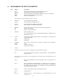
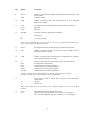
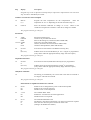
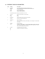
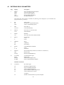
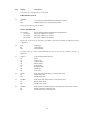
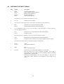
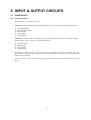
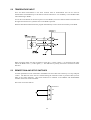
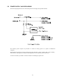
The power supply and grounding circuit is detailed in Section 5.5. Definitions are:
Chassis Ground
These terminals are for shielding purposes and the Chassis Ground is connected to the aluminium case of
the instrument. A terminal on the side of the case enables a solid connection between the case of the
instrument and the vehicle.
Note that the Chassis Ground is NOT 0 Volts or Signal Common and should only be used for shielding
purposes.
It is recommended that the flowmeter inputs, temperature inputs, communication links and remote switch
input all use shielded cable with the shields connected at the Trac-40 only.
In order to comply with the requirements for Electromagnetic Compatibility as per EMC-Directive
89/336/EEC of the Council of European Community, shielding on all signal cable at the instrument only
is mandatory practice.
0 Volts Common
This signal is the Signal Common for the communications lines, Pulse Output, End of Batch and Flow
Alarm Outputs and the dc Voltage Output.
+Vout
Connector 2 Terminal 8 is the regulated dc output which can be used to power the flowmeters. The
negative of this supply is 0 Volts Common.
+Vout Auxiliary and 0 Volts Auxiliary
These auxiliary terminals are connected directly to the power input on Connector 4 Terminals 1 and 2.
The auxiliary terminals are used to provide power to printers or Hand-held computers.
Note that 0 Volts Auxiliary should not be used as a signal ground.
9.2 DC SUPPLY OUT
A supply output voltage is provided to power sensors. This output will provide a regulated voltage of 8 to
24 Volts and the voltage is adjustable by means of the potentiometer on the rear panel. Maximum current
is 50mA and the instrument comes with the voltage factory set at 24 Volts. When the instrument is
powered from a DC power source, the maximum output voltage on the supply output is the DC input
voltage less 3.5 volts.
56