1
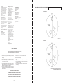
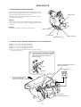
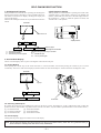
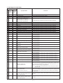
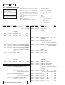
1-3. CAMERA SYSTEM ADJUSTMENTS
Before perform the camera system adjustments, Check that the
specified value of “28MHz Origin Oscillation Adjustment”, “Y OUT
level Adjustment” and “C OUT level Adjustment” of “VIDEO
SYSTEM ADJUSTMENT” are satisfied.
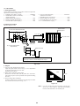
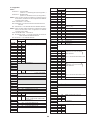
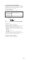
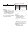
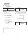
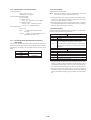
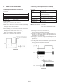
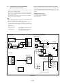
1. G-CAM flip Adjustment
Set the color reproduction conditions to optimum.
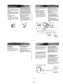
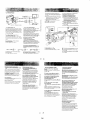
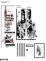
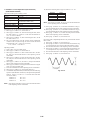
Subject
Measurement Point
Color bar chart standard picture frame
Display data of page 1 of the adjusting
remote commander (Note 1)
Measuring Instrument
Adjustment Page
Adjustment Address
F
21
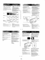
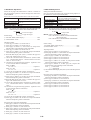
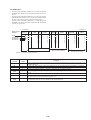
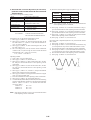
Note 1. Displayed data of page 1 of the adjusting remote
commander.
1 : XX : XX
n S2
n S1
Note 2. [ ] : CCD-TR311/TR640E/TR730E/TR840E/TR845E
< > : CCD-TR311E/TR411E/TR412E/TR511E/TR512E
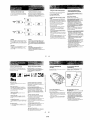
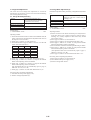
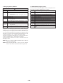
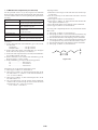
Adjusting method:
1) Select page: 0, address: 01, and set data: 01.
2) Select page: 0, address: 03, and set data: 16.
3) Select page: F, address: 21, set data: [D2] <D0>, and press the
PAUSE button of the adjusting remote commander.
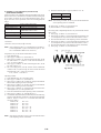
4) Select page 1 of the adjusting remote commander, and compare
the higher 2 digits (S1) and lower 2 digits (S2) of the 4-degits
display data.
When S1<S2
Perform steps 5) onwards.
When S1 S2
Perform steps “Processing after Completing Adjustments”.
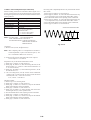
5) Select page: F, address: 21, set data: [52] <50>, and press the
PAUSE button of the adjusting remote commander.
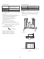
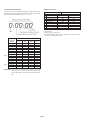
Processing after Completing Adjustments
1) Select page: 0, address: 03, and set data: 00.
2) Select page: 0, address: 01, and set data: 00.
5-13