1
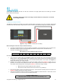
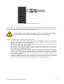
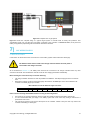
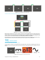
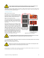
Figure 6.4 Completed 12V off-grid system Figure 6.4 shows the complete wiring of a typical off-grid system. It includes fuses for safety and protection. This configuration shows only one panel and one battery connected to the controller. In Sections 8 and 9, more panel and battery configurations (respectively) will be described. Instructions will follow. 7| 24V WIRING BASICS 7.1 General information In this section we will show the basic connections for a 24V battery system. Please follow them thoroughly. The batteries must first be wired to the charge controller before the solar panel is connected to the charge controller. Caution! As we mentioned in Section 6.1, the battery bank must first be connected to the charge controller before any other connections are made. This will allow the controller to set the 24V charging parameters automatically. Before starting the connections keep in mind the following: The charge controller should be as close as possible to the batteries. This helps keeping line loss to a minimum level. Remember to always use the recommended gauge size based on the total input current. The PWM 30A LCD controller can handle gauges up to 8 AWG. NEC maximum current for different copper wire sizes AWG Max. Current 16 10A 14 15A 12 20A 10 30A 8 55A 6 75A 4 95A 2 130A 0 170A Please note the following about PWM controllers running in 24V configuration: 24V panels or 12V panels configured in series to make 24V should be used with 24V battery system only It is not recommended that you charge a 12V battery system with a 24V solar array. Doing so will result in a performance loss of 50%. The solar array should not max out the rated power of the controller. Failure to obey this rule may result in the controller overheating or catching fire. Copyright © 2014 Renogy. All Rights Reserved. 15