1
Please read these instructions carefully before attempting to carry out any installation and
wiring. Contact Technical support for any questions concerning the installation.
Warning!
This equipment should be installed, adjusted, and serviced by qualified electrical maintenance personnel familiar with the
construction and operation of solar/electrical equipment and the hazards involved. Failure to observe this precaution may
result in bodily injury and/or damage to property.
10.2 Wiring instructions
Step 1: Select the right input voltage
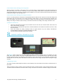
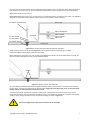
Input voltage can be 12V/24V/48V depending on which
products are used. It is recommended that the inverter be
powered by a battery or battery bank, as the current
drawn from the inverter can become extremely high.
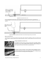
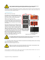
Step 2: Connecting inverter to battery
Set the switch to OFF position (inverter and appliances).
Connect the battery cables to their respective colors on
the inverter i.e. black cable goes to the black terminal on
the inverter, and the red cable goes to the red terminal
on the inverter.
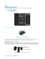
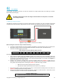
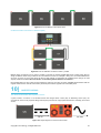
Please refer to Fig. 3. Each end of the battery tray cables
should have a “ring terminal” type of connector. These
connectors make it easy to achieve a secure and strong
connection. Once the cables are connected and bolted
down to the inverter, connect the black cable to the
negative post of the battery (-). Then, connect the red
cable to the positive post of the battery (+). If connecting
to a battery bank, make sure that the black cable
connects to the negative battery post (-) at the end of the
bank (opposite to the positive battery post as shown on
Fig. 3). It is recommended that a fuse be placed on the
hot line (positive) between the battery and inverter.
Please refer to the owner’s manual for the proper wire
gauge size and fuse ratings for each inverter.
Figure 10.2 Inverter wiring diagram
The negative battery terminal and the chassis ground of the inverter should be connected
to a system ground. This is a safety measure to prevent electrical shock!
Ground!
NOTE: The charge controller and the inverter should be connected to the same battery terminals (same connecting
points shown in Figure 10.2), no exceptions.
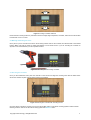
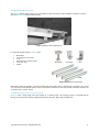
Step 3: Connecting electrical appliances to inverter
Make sure the power load is within the rated power of the inverter. The start power of the
appliances should not exceed the peak power of the inverter.
Caution!
Once the devices are connected to the AC outlet, they are ready to be powered. When the inverter is not in use, it is
recommended that you turn off the inverter (switch in OFF position).
Copyright © 2014 Renogy. All Rights Reserved.
23