1
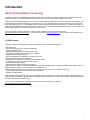
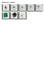
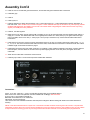
LP-PAN
Software Defined
IQ Panadapter
Operating &
Assembly Manual
June 2008
TelePost Incorporated
Rev. A9
Work in Progress… may have errors!
1
Table of Contents
Introduction ............................................................................................................ 3
Parts List................................................................................................................. 4
Assembly ................................................................................................................ 7
Installation & Setup ............................................................................................. 11
Operation.............................................................................................................. 16
Circuit Description ............................................................................................... 18
Schematic ............................................................................................................ 19
Troubleshooting ................................................................................................... 20
Specifications and Warranty ................................................................................ 21
Appendix A .......................................................................................................... 22
Copyright and Trademark Disclosures
LP-PAN is a trademark of TelePost Inc. Windows® is a registered trademark of Microsoft Corporation. Material in this
document copyrighted ©2007,8 TelePost Inc. All rights reserved. LP-Bridge copyrighted ©2007,8 TelePost Inc. All rights
reserved. PowerSDRTM is an open source application for use with IQ based software defined radios, and is a trademark of
FlexRadio Systems.
2
Introduction
Read Carefully Before Continuing.
Assembling LP-PAN is a straightforward job, and you should have no trouble if you follow the instructions. Take special note of the
connection diagram, and become familiar with the basics of how the various components fit together in the system.
Installing and configuring PowerSDR can be tricky. It is a complex program, and requires quite a few steps to get set up properly. Lots
of Flex Radio users have done this though, so don’t let it scare you. Pay special attention to the sound card setup. If you’re using the
E-MU 0202 USB sound card, you will probably want to visit the Creative Labs website for the latest driver. The E-MU driver does not
support Windows 2000, but works with XP and VISTA, 32 and 64. There is some question about whether there may be a problem in XP
SP3 though. I believe SP3 port dates the latest E-MU driver, though.
If you get in trouble, help is an email away. There are plenty of helpful users on the LP-PAN User Group,
http://groups.yahoo.com/group/LP-PAN/ , or you can send an email to [email protected]. Phone support is also available at 734455-3716.
LP-PAN Features
LP-PAN is a software defined IQ direct conversion panadapter. Here is a list of current features...
* Optimized for K3
* Up to 192 kHz display on PC, sound card dependent
* Display centered on K3 IF
* Switching quadrature detector for high dynamic range
* Strong buffer amp with low NF and very high LO isolation.
* Excellent THD and IMD performance
* Ground isolated inputs / outputs with high quality audio xfmrs
* 600 ohm output Z, balanced or unbalanced.
* Fully balanced architecture with balanced and unbalanced outputs
* Jumperable ground lift on RF input and audio outputs
* Works with many SDR programs.
* Adjustable gain to interface almost any sound card
* Point and click frequency control with PowerSDR / IF Stage and LP-Bridge or HRD . In addition, LP-Bridge allows sharing of K3 / LPPAN with almost any logger, and even programs such as CW-Skimmer
* Will be available for other common IF frequencies in the HF region as custom order in future production runs.
* Powder coated aluminum enclosure with silk screened graphics.
* Hardware or software mute
Note: Specifications dependent on sound card, and subject to change. Cited values were taken with an E-MU 0202 USB sound card.
All measurements also apply to M-Audio Firewire Audiophile 2496 card (limited only by 96 kHz display width). Measurement details are
included in the Performance section below.
For an up to date comparison of sound cards, check out the Sound Card page on my website at
http://www.telepostinc.com/soundcards.html
3
Parts List - Subject to change without notice. Pictures shown at end of parts list.
Pre-installed SMT parts
Quantity Designation
5 C5,11,18, 31, 39
2 C4, 6
1 C7
1 C9
1 L4
1 L8
2 L9,10
0 L11, 12
2 R1, 3
1 R4
1 R5
2 R6, 7
2 R8, 28
1 T3
1 T4
1 U11
1 U2
2 U4,7
1 U5
1 U8
Description
0.01uF
0.1uF
1uF
0.22uF
10uH
15uH
0.11uH
0.11uH (alternate)
1K 1%
4.7K 1%
200 ohm 1%
499 ohm 1%
49.9 ohm 1%
Toroid XFMR 1:1
Toroid XFMR 4:1
ADCMP600 Comparator
74HC/HCT163 Counter
LT6231 Low Noise Op-Amp
AD8007 Transconductance Amplifier
SN74CBT3253D 4x2 Analog Multiplexer
Through-Hole Parts
Quantity Designation
1 C1
6 C2, 3, 8, 20, 40, 42
Note:C40 changed to
-- C10
1 C12
1 C13
6 C14,16,22,24,27,37
5 C15,17,23,25,38
2 C19,26
Note:C19 changed to
2 C21,28
1 C30
2 C34,35
1 C36
1 D1
1 J1
2 J2,13
1 J3
1 J11
4
3 JP1-3
1 JP4
6 L1,2,3,5,6,7
1 Q1
1 R2
4 R9,17,18,34
5 R10,12, 14,15,16
1 R11
Value
33pF ceramic (marked 33) Fig. 3
0.1uF monolithic (marked 104) Fig. 1
0.001uF disc (102) starting with ser.#101
Not used in K3 version
15pF ceramic (marked 15) Fig. 3
22pF ceramic (marked 22) Fig. 3
0.01uF ceramic (marked 103) Fig. 3
1uF (25V electrolytic) Fig. 2
10uF (25V electrolytic) Fig. 2
100uF on later units. Fig. 28
3300pF ceramic (marked 332) Fig. 3
39,47, or 51pF SM (marked 39, 47, 51) Fig. 4
4-20pF trimmer cap Fig. 19
56pF ceramic (marked 56) Fig. 3
Green LED Fig. 9
Insulated BNC connector Fig. 17
3.5mm Stereo Audio Jack Fig. 20
RCA Jack Fig. 21
2.5mm DC Power Connector Fig. 7
2-pin Jumper Fig. 11
2-pin Header Fig. 11
3-pin Header Fig. 11
1mH RF Choke (br-bk-rd) Fig. 5
MPS5179 transistor Fig. 10
10 ohm 1/8W res. (br-blk-bk) Fig. 12
1K 5% 1/8W res. (br-blk-rd) Fig. 12
2.2K 1% 1/8W res. (rd-rd-bk-br-br) Fig. 12
1.5K 5% res. (br-grn-rd) Fig. 12
4
Parts List – Cont’d
Quantity designation
4 R13,19,20,27
2 R21,22
1 R23
2 R24, 35
1 R25
1 R26
1 R29
1 SW11
2 T1,2
1 U1
1 Y1
1
1
1
Value
22 ohm 1% 1/8W res. (rd-rd-bk-gld-br) Fig. 12
2K 5% 1/8W res. (rd-bk-rd) Fig. 12
1K Pot Fig. 22
10K 5% 1/8W res. (br-bk-or) Fig. 12
27K 5% 1/8W res. (rd-viol-or) Fig. 12
470 ohm 5% 1/8W res. (yel-viol-br) Fig. 12
200 ohm Pot Fig. 23
4PDT Pushbutton Switch & Keycap Fig. 6
Audio Output Xfmr, 600 ohm Fig. 25
LM7805CT 5V Regulator Fig. 18
32.860MHz or 32.836 MHz Crystal Fig. 24
PCB Fig. 26
Enclosure Fig. 27
Power Cord Fig. 8
Hardware
Quantity designation
6
8
4
4
Value
¼” Black Sheet metal screw Fig. 14
3/16" Black machine screw Fig. 15
1/4" standoff Fig. 13
Rubber feet Fig. 16
Fig. 5
Fig. 1
Fig. 2
Fig. 3
Fig. 4
Fig. 6
Fig. 7
Fig. 8
Fig. 9
Fig. 10
Fig. 11
Fig. 12
Fig. 13
Fig. 14
Fig. 15
Fig. 16
Fig. 17
Fig. 18
Fig. 19
Fig. 20
5
Parts List – Cont’d
Fig. 21
Fig. 22
Fig. 23
Fig. 26
Fig. 27
Fig. 28
Fig. 24
Fig. 25
6
Assembly
Important warnings – read this before starting assembly
You should visually inspect all the solder pads/traces with a magnifier for any etching problems. This is done before shipping, but I
recommend the builder do a second inspection as well. We do 100% continuity checks of all pads before shipment using computer
controlled flying probes based on PCB netlist coordinates.
All of the SMT components are pre-installed on the main board for your convenience. SMT parts are supplied wherever necessary for
performance or availability reasons. CAUTION: Be very careful handling this board to avoid damage to the installed parts. Anti-static
measures are highly recommended, such as use of an anti-static mat, grounded soldering iron and wrist band.
You may wish to clean the flux from the board after assembly, although it is not necessary with most modern solders. A toothbrush and
alcohol are good for this. Only use rosin core solder. Use of acid core solder voids the warranty. Lead-free solder is OK, and the boards
are RoHS compliant, but it will be more difficult to remove parts without damaging the board should you have to.
Overview
Below is the component placement diagram for the main PCB. These markings match the silk-screening on the PCB, but are repeated
here for clarity. You can also cross out the parts on this graphic as they are installed.
You should check all parts before starting to allow you to start the process of obtaining replacement parts as soon as possible. It is also
a good idea to sort the parts in advance… egg cartons are handy for this (passive parts only). Many crafts stores, Like Michael’s, also
have nice plastic cases with dividers at low prices. If there is any doubt about component values, especially with the 1% resistors which
can use strange markings, check them with your DMM.
7
Assembly Cont’d
Pre-assembly overview.
When assembly starts on page 10, it will roughly follow this order…
Installation of resistors
Installation of capacitors
Installation of connectors and switches
Installation of 7805 regulator
Installation of chokes
The idea is be able to lay the board flat as much as possible during construction, with lowest parts being installed first. The chokes are
the lone exemption… they are installed last so as to make sure each circuit is drawing the right amount of current before continuing.
Here are the target current measurements taken after installation of each of the chokes…
No chokes
L5
L7
L1
L2
L3
L6
26mA
27mA
37mA
39mA
42mA
48mA
54mA
You will need the following tools to complete assembly…
Adjustable soldering iron – 800 degrees maximum
60/40 alloy solder… .020” (0.51mm) diameter recommended for thermal pads
Needle-nose pliers
Wire cutters
Small Philips head screwdriver
Digital Multimeter
NOTE: The LP-PAN is an intermediate level kit. I would peg the assembly time at about 2-3 hours, plus some reading through the
manual in advance, and some time for calibration afterward. Take your time, and double-check your work, and you should have no
problem. All critical parts are pre-installed.
8
Assembly Cont’d
Step-by-step assembly instructions.
Below is a picture of the assembled PCB. The SMT parts come pre-installed.
It is recommended that you print at least this portion of the manual to allow for easy reference while building, and to allow you to check
off the steps as you complete them. Make sure your work area is static-free to avoid damage to the pre-installed SMT parts. It is also
advisable to wear an anti-static wrist band and grounded soldering iron. Refer to the parts placement graphic on page 6 or the above
picture for questions regarding parts placement.
q
Install resistors. To avoid messiness when trimming leads, I would do about 6 at a time. Follow the parts list and check them off as
you go. If you are unsure of the colors used by some of the manufacturers for the color code, especially the 1% parts, measure the
value with a DMM.
q
Install all .01 uF caps (marked 103).
q
Install all 0.1 uF caps (marked 104). This should be done in at least two batches. Note: C40 changed to 0.001 uF(102) starting with
serial #101.
q
Install remaining ceramic and SM caps, and the two trimmer caps. Do not install the electrolytics yet.
q
Install the two audio jacks next. Solder the center lead first, so that you can adjust the jacks to be parallel with the
board edge before soldering the remaining pins.
q
Install D1 (LED), Q1, R29 (pot), SW11.
q
Install J3. You will need to clip off the two plastic tabs on the bottom of the connector off before installing. Latch the rear pin first for
strength, then solder the front pin.
q
Install J11
q
Install the three 2-pin and one 3-pin headers. Install a shorting jumper between pins at JP2. Install a jumper on the ground pin only
on JP1 & JP3. Install a jumper between pins 2 & 3 of JP4 (the two toward the front of the board).
9
Assembly Cont’d
q
Install T1 and T2. The PRI side goes toward the ICs, and the SEC side goes toward the back of the board
q
Install R23 (pot)
q
Install J1
q
Install crystal, Y1
q
Install the electrolytics, taking care with polarity. The “+” lead is the longer one, “-“ lead is marked with a black or white stripe, or
blue semi-circle. Note: On later units, C19 was changed to a 100uF low ESR electrolytic to eliminate a very low frequency parasitic
oscillation that appeared in the oscillator of a few units. This had the effect of degrading the overall noise floor when very strong
signals (>S9+30dB) were in the passband.
q
Install U1, the 7805 regulator
q
Make sure that your bench is clean and the PCB is not sitting on any cut off component leads. Connect supplied power cable to a
supply of 11-16 VDC. The dashed white lead on the supplied power cable is the + lead (center pin). The green LED should light.
Using your DMM, check for 5.0 VDC (+/- 0.25V) at pin 3 of U1 (the pin connected to C3). Current draw should be about 25mA.
Power down.
q
Install chokes one at a time, and check current draw between each one to verify no unusual current draw. Install in order… L5, L7,
L1, L2, L3, L6. The current should increase a little with each choke, and should reach a maximum of about 54mA with all 6 chokes
installed. Target current levels are listed on page 8.
q
Install PCB in enclosure using 3/16” black screws and ¼” standoffs. Loosely install the standoffs on the bottom, and then slide the
board into place, rear first. Attach the screws from the top while aligning the holes on the rear panel, then tighten the screws
underneath.
q
Attach the four rubber feet to the bottom of the enclosure.
q
Install keycap on SW11. The enclosure top will be installed after calibration.
Connections…
Power: 11-16 VDC, center pin +, 2.5mm. The lead with the white stripe on the supplied cable is +
Mute: Gnd to mute. 5VDC max (software mute also available with LP-Bridge). See note below.
IF Input: From rig. 8.215 MHz for Elecraft K3
Bal/Unbal: Out for balanced, In for unbalanced
I/Q Outputs: To sound card inputs
Level: Used to fine tune load balance between channels (Name changed to “Match” starting with serial #101 to better describe its
function).
NOTE: It was discovered that there is a layout error in the first two hundred LP-PANs concerning the mute connector. The pads were
inadvertently reversed. Since the connector shell is isolated from ground, this should not pose a major problem as long as care is taken
to keep the shell from touching ground. Anyone using hardware mute should remember to wire the mating RCA plug backwards.
10
Installation and Setup
System Overview
Before starting, it helps to read this section in order to understand the basics of how the K3, LP-PAN, PowerSDR, Sound Card and LPBridge (or HRD) work together. In general, the duties of each part of the system are as follows:
LP-PAN – Provides audio baseband IQ signals for application to a high quality sound card, which becomes the interface to PowerSDR.
The signals are derived from the broadband IF output of the K3.
PowerSDR – Provides decoding and processing of the audio signals. In addition to providing a panadapter or waterfall display,
PowerSDR is actually a full receiver AND sub-receiver with very high quality on its own. It rivals the K3 in many ways, and adds some
features not available on the K3.
LP-Bridge - Provides a serial interface to the K3, and computer links to PowerSDR. This allows linking of the K3 to PowerSDR for
Frequency, Mode, Preamp setting, Mute and other future function links. A serial cable is required between the K3 and the PC to enable
the communication link. Without this link, PowerSDR will act as a panadapter with “relative” frequency display, for instance, +/- 96 kHz
from a center “zero” frequency which represents the center of the IF.
Sound Card – The link between LP-PAN and PowerSDR. A high quality sound card is required. These are available for about $100.
See the sound card page on the TelePost website for latest recommendations. http://www.telepostinc.com/soundcards.html
Above is a diagram showing typical setup of the LP-PAN system.
11
Installation and Setup cont’d.
Initial Settings
Set JP1 & JP3 to open, JP2 to shorted, and JP4 to pins 2 & 3, as shown in the photo on page 3. Set gain pot R29 to fully counterclockwise (max gain), and the load balance rear panel level pot to full clockwise.
Hardware Setup
The connection to the sound card will be largely determined by the sound card inputs. Here are some common possibilities…
Sound card with a pair of unbalanced mono inputs (as in E-MU 0202, shown above).
Set Bal/Unbal switch to Unbalanced (IN). Use a pair of mono cables with the appropriate connectors on the sound card end. In the case
of the E-MU 0202, these will be ¼” phone plugs. Note: The left channel input on the E-MU uses a “funny” connector, but accepts a ¼”
mono phone plug. DO NOT use a stereo plug here, as it can get hung up on the ridges around the middle ring.
Sound card with a pair of balanced mono inputs (as in Delta44).
Set Bal/Unbal switch to Bal (OUT). Use a pair of stereo cables with 1/8” male on LP-PAN end and appropriate connectors on the sound
card end.
Sound card with a single stereo input (typical of inexpensive SoundBlaster type cards).
Set Bal/Unbal switch to Unbal (IN). Use a pair of 1/8” mono cables on the LP-PAN end, and a Y connector or adapter to combine them
into one stereo connector at the sound card end. Generally speaking, a red connector indicates right channel and white indicates left
channel, if marked.
In most cases, your monitor speaker will connect to the stereo output jack or headphone jack of the sound card or PC, depending on
setup. You may need a Y adapter for some cards to combine two mono outputs into a stereo monitor output. If you plan to use the subreceiver in PowerSDR, stereo speakers are very useful as the two receivers are routed to different channels.
Connect the RF input of LP-PAN to the IF output of the K3 using a short, high quality 50 ohm jumper cable with male BNCs on each
end.
The term mute in context with PowerSDR means the muting of the audio output of PowerSDR when transmitting. Normally, mute is a
software function handled by LP-Bridge and PowerSDR. It can be disabled by selecting MON in PowerSDR if you want to hear your
transmit signal. PowerSDR always displays the spectrum of your low level transmit signal. Hardware mute will not be needed by most
operators. In general, LP-Bridge will provide fast enough muting to handle muting in software for VOX or semi-break-in CW keying. This
is not the case with HRD, which has a sizable delay. QSK keying might require the hardware mute input, but because of PowerSDR’s
reaction to major changes in level, it might make sense to break the PC speaker connection for muting instead
The mute input is designed for connection to isolated relay contacts or an open collector transistor driver. Voltage on the mute
connector should not exceed 5VDC nominal logic levels. In other words, you cannot share a PTT line with an old style linear amplifier
with high voltage keying without an additional relay.. Note: On serial numbers below 200, the mute connector is wired backwards of you
would typically expect. In other words, the voltage is on the shell and the gnd is on the center connector. As long as you don’t ground
the shell, this should not affect operation. I recommend wiring a plug in reverse to match the jack, so that the far end of the plug cable is
correct.
LP-PAN can be powered from a RigRunner type power manifold, a wall wart (11-16VDC at 50mA) or the Accessory DC jack on the
back of the K3. The wire on the supplied power cable with the white line is positive voltage (center pin of DC connector). Before power
up, make sure that LP-PAN is sitting where the bottom of the board can't contact anything metallic, of course ;-)
PowerSDR Setup
Download PowerSDR/IF Stage from Scott McClements, WU2X’s web site, http://www.wu2x.com/sdr.html#powersdr Follow the
instructions on his web page for installation and initial setup. Download LP-Bridge from the TelePost web site at
http://www.telepostinc.com/downloads/LP-Bridge.zip Install both programs in their default directories. Note: Both programs are beta
versions, and as such are not complete, but should be fully functional at their current level of development.
12
Installation and Setup cont’d
The following assumes that you will be using PowerSDR/IF Stage and either LP-Bridge or HRD for testing...
Start LP-Bridge or HRD and set it up to talk to the K3. The K3 should be set for 38,400 baud. Start the K3 control program first, then
start PowerSDR/IF Stage. After PowerSDR starts and initializes the FFTs, select Setup and the General tab. (Refer to Operation
section of this manual for a picture of PowerSDR). Select SoftRock IF Stage in the Radio Model tab. Leave all other settings as they
are.
Go to the Setup>Audio tab, and set the sound card to “Unsupported Card”. Select the correct driver for your sound card. For most
modern professional sound cards, this will be ASIO, but if the card is older you may have to use WDM-KS. Set the audio Input, Output
and Mixer for your sound card. Mixer can be set to None if you are only going to monitor PowerSDR. Set the sample rate to the
maximum supported by your card, set Buffer Size to 2048 and click Apply. Other settings can be left as is, although I found with my EMU 0202 card that it wouldn’t start reliably unless I selected Expert Mode and set Latency to 2ms.
In the Display tab, the vertical scale should be set for a displayed range of -10 to -130 dBm for now (entered range of +10 to –150dBm).
I set Averaging to 100ms, but you may find a different value better. This determines the averaging when the AVG button is pressed in
the main PowerSDR screen, and trades off lower noise for update lag. All other settings can be left as is for now.
On the main PowerSDR screen, click on the Standby button and you should hear LP-PAN. The display window in PowerSDR should be
set for "panadapter", and AVG turned on now. The noise floor with no antenna connected to the K3, K3 preamp OFF, PowerSDR
preamp setting set to OFF, should be about –115 to –120dBm, and should be flat with no signals shown. If you are using a E-MU 0202
USB card, the input gain controls should be set to between 9 and 10 o’clock to get this noise floor. Many professional sound cards will
have fixed inputs. If your card uses a software level control, it should be set near maximum with line input, and should show the
indicated noise floor as mentioned above.
If you are seeing any signals, then there is something in your cabling / ground lift settings that is not right. Small blips, say 10dB above
the noise floor could be the result of radiation from your monitor or USB cabling, and rearranging things might help. I had tiny blips on
an older PC with a 21" CRT monitor, and had to move the sound card away from the monitor. On my laptop and other PC with LCD
monitor I had no problem. Small blips should not be a problem in practice, especially with AVG off.
Connect an antenna, and the noise floor should jump up a bit, depending on band, and you should see lots of signals if the band is
open. I recommend 40m as a good starting point, since there are always signals, and at night you can see some very strong ones.
To display maximum bandwidth, the PAN slider should be centered, and the Zoom slider should be all the way to the left. The
frequency display should more or less match the HRD and rig display, although there are some offsets that have to be precisely set to
align it with the K3 in terms of exact audio pitch. This varies from rig to rig and has to do with the filter centers in the K3, CW pitch
setting and tolerance of the 32.860 MHz xtal in the LP-PAN LO.
The offsets will be adjusted after the LP-PAN hardware adjustments are completed in the next section.
13
Installation and Setup cont’d
Hardware Calibration
There are only a few hardware adjustments that need to be made in LP-PAN… filter peaking, overall gain setting and load balance. All
adjustments are made while monitoring the PowerSDR display. Load balance is done in conjunction with the Image Rejection controls
in PowerSDR.
Filter adjustment - To adjust the filter, tune to a strong signal, S9 or better, and peak C35 for maximum strength. If you don’t have an
insulated tuning tool, a small screwdriver can be used, but you will have to remove the screwdriver between adjustments to see the
effect of the adjustment. After C35 is peaked, adjust C34 for maximum signal.
Gain adjustment - To set the gain display accuracy requires a signal source with known output level. This can come from a calibrated
signal generator, or something as simple as the Elecraft XG1 or XG2 test oscillators, which have an output of about –73dBm
(50uV/S9). Set the K3 preamp and attenuator OFF, and the Preamp setting in PowerSDR to OFF. Turn AVG on in PowerSDR. Adjust
the gain pot, R29, for a displayed level of –73dBm for the generator output. The setting should wind up near the beginning of the pot
rotation (full CCW is max gain). If the pot winds up at more the half, then you probably need to increase the sound card input levels if
they are adjustable. The pot has about 8dB range. If you have an adjustable generator, you can check sound card gain for proper
range. The sound card should clip at a generator output level of about –5dBm with K3 preamp and attenuator OFF, and PowerSDR
preamp setting on OFF.
Image Rejection Adjustment - At this point, strong signals will display an image on the opposite sideband, with 2nd harmonics at about
70dB down. Image rejection is adjusted in the DSP tab in PowerSDR Setup, under the “Image Reject” tab. If your sound card has
manual input pots, make sure they are set for the same level. Also, if there is a balance control, make sure it is centered. If your sound
card has software level controls, set both channels for the same level. You can set a quick image null by placing the signal and image
near the center of the display, separated by a few kHz. AVG should be OFF for these adjustments. Adjust the phase and gain sliders
for minimum amplitude of the image. Fine tuning requires using the Up/Dn arrows.
This will not be the best setting for overall broadband image rejection, however. There is an iterative process for improving the
broadband image rejection, which essentially finds a median setting which will be close for all frequencies, but not perfect at any one
frequency. The procedure is outlined below.
1)
2)
3)
4)
Tune in a strong signal (-50dBm or higher) from a signal generator or nearby transmitter.
Tune the K3 to put the image midway between the center of the display and the left end of the display.
Set the Image Reject Phase and Gain adjustments for minimum image response. Log the values.
Retune the K3 to put the image signal midway between the center and the right end of the display. Adjust for minimum response
and log the values.
5) Set the Image Reject controls for the midpoint of the logged settings.
6) Adjust the control on the rear panel of LP-PAN (Level or Match, depending on serial #) for minimum response
7) Retune the image to the original center/left point. Readjust the gain setting in PowerSDR for minimum image. Log the value.
8) Retune the image to the center/right point and readjust the gain setting for minimum image. Log the value.
9) Adjust the gain setting for midway between the two values if they are not the same.
10) If the gain settings logged in steps 7 & 8 are not very close (within 1.0), then you can repeat steps 6-9 to get closer.
When finished, image rejection should remain at 60dB or more over almost the entire range as you tune, with maybe 55dB at the edges
and about 75dB at its highest point.
You should now be ready to attach the enclosure top.
14
Installation and Setup cont’d
Software Calibration
The offset controls are located in “SoftRock IF Stage” tab under the General tab in PowerSDR setup. They are identified as IF
Frequency. I will probably add them to LP-Bridge as well to keep from having to keep updating PowerSDR. It is easier and faster for me
to update LP-Bridge than for Scott to update PowerSDR. The default settings in PowerSDR-IF Stage are for the SDR-1000, which uses
an 11 kHz offset. They will not work with LP-PAN. Here are the settings I use as a starting point…
LSB… -2735
USB… 966
CW… -2685
CW and LSB are different in this case because I am using a 5-pole filters, and they each have their own offset. In the future, LP-Bridge
will keep track of filters in use and read and apply the correct offset, which is data that will be available from the K3.
To set your offsets, put the K3 in LSB and tune a carrier into the passband for a convenient tone on the K3 speaker/phones. Make sure
PowerSDR also displays LSB mode, and turn the speakers up that are connected to your sound card. The LSB offset control should
now be adjusted to place the carrier in the green passband window in PowerSDR. You should hear a tone from the sound card
speakers. You can adjust the offset for large steps by entering numbers in the box. Small steps can be made using the Up/Dn buttons.
Don’t press and hold an Up/Dn button, as it can crash the program. Click once for each step. Adjust the offset control until the two tones
are zero beat. You may want to tune the K3 a little to find a tone that makes it easy for you to hear the zero beat.
Once you have finished for LSB, repeat for the other modes.
LP-Bridge (not released yet)
LP-Bridge is very easy to set up and use. (This picture may or may not represent the current state of development of LP-Bridge).
Simply select the com port that the K3 is connected to using the pull down menu under K3 Com Port. The K3 should be set for 38,400
baud for maximum throughput. Click Enable under the PowerSDR section. (The offsets haven’t been implemented yet).
Virtual com ports are selected the same as the K3 com port. You can select any unused port number on your PC. You can also assign
an alphanumeric name to the port to keep track of what program is using each port. Any program connected to that port will think it is
connected to the K3 directly. You can have up to three simultaneous connections to the K3, in addition to PowerSDR.
I will add more to this section as LP-Bridge becomes available and evolves.
15
Operation
Above is the normal PowerSDR-IF Stage display. Most of the controls are not active for LP-PAN use, including all transmit controls.
AGC… Adjusts the AGC setting for PowerSDR reception only (not K3).
Preamp… Adjusts the vertical scale to correspond to the K3 preamp condition. LP-Bridge is required for this to happen automatically.
With K3 preamp “OFF”, the PowerSDR mode should be OFF. With the K3 preamp ON, the PowerSDR mode will be “Low”.
DSP Section… These apply only to PowerSDR reception.
Sub Rx Section… Applies to PowerSDR receiver channels. The vertical sliders do nothing, the horizontal ones allow panning of the
main and sub receivers to left and right speakers.
Display Mode… A number of modes exist, including Panadapter, Audio Scope, Waterfall, etc. Also, AVG and Peak modes of display
are selected here. Applies only to display.
Band… Selects band for both PowerSDR and K3. This can be used as a quick way to change bands.
Mode… Selects mode for both PowerSDR and K3. Modes not supported in K3 are ignored by K3. Modes such as DRM require
additional software to decode. SAM is Synchronous AM mode.
Filter… Selects PowerSDR DSP filters. These can be set differently than K3 if desired (for instance to listen to a wider CW passband
than what is selected in K3).
Width and Shift… Apply to PowerSDR IF shift controls.
RX EQ… enables graphic equalizer for PowerSDR receiver. The equalizer can be set in the Equalizer pull down menu at the top of the
program.
RX Meter… allows several different modes for the S-Meter
Pan & Zoom… adjusts the portion of the passband that is displayed in the panadapter. Wide display is far left in zoom bar, PAN should
be centered.
16
Operation cont’d
In normal operation, The panadapter sliderule display moves as you tune the K3. You can also left click and drag the display to tune the
K3. Right clicking will display a crosshair which can be used for “point and click” tuning to the signal under the cross hair. Left clicking
while the crosshair is centered on a signal will snap that signal into the passband of both PowerSDR and the K3. You can listen to just
the K3, or to just PowerSDR or both. If the offsets have been set properly, they should sound the same.
In addition, PowerSDR has a sub receiver which can be tuned independently to any frequency within the display. Click on SubRX to
activate it. Normally, the main receiver audio goes to the left speaker and the sub receiver audio goes to the right speaker. You tune the
sub receiver by grabbing the blue passband bar and sliding it left or right.
Currently PowerSDR-IF Stage does not support tuning of the sub receiver from the K3’s VFO-B knob, but I have asked Scott to add
this. Support for this already exists in LP-Bridge. I have also asked that the behavior of the main tuning knob be changed so that the
green main passband moves as you adjust the K3 tuning, and the background stays still unless you drag it to a different segment of the
band. That would also allow any changes in Split operation to be transferred back and forth between the K3 and PowerSDR.
Also on the list of future enhancements is offset feedback from the K3. This is needed because of the various filter offsets, as well as
during adjustment of the K3’s DSP controls. As the controls are adjusted, the 1st IF signals shift within the K3 passband. These shifts
are corrected later in the K3’s DSP, but of course that doesn’t help the panadapter. Elecraft have indicated that they will provide these
offsets in the future. LP-Bridge is set to take advantage of them once they’re ready.
Scott also plans to add auto image nulling in PowerSDR along the lines of what is done in the Rocky program. This would provide an
image rejection of about 100dB with no adjustments.
17
Circuit Description
LP-PAN is a direct conversion quadrature receiver with baseband audio In-Phase (I) and Quadrature (Q) outputs. These outputs are
fed to a high quality sound card for DSP processing in applications such as PowerSDR. The input is taken from the IF output connector
of a receiver. Values shown are for Elecraft K3. The signal has a very wide bandwidth, and is bandpass filtered down to about 400 kHz
in the front end of LP-PAN. This helps with out of band signals that are strong enough to get by the K3’s input filters, and also
eliminates mixer products that are present in the K3’s IF output.
The filtered signal is then sent to a high isolation buffer amplifier. This amp serves a couple purposes. One is to add gain lost in the K3
IF output stage, which is quite lossy. The second is to isolate the K3 from the strong L.O. signal present at the input of the quadrature
mixer. The buffer amp has over 80 dB of isolation, and is capable of reducing the L.O. leakage to a level well below the K3’s noise floor
in combination with the K3 internal buffer. The buffer has a very low noise figure, and high IP3 (>+40dBm) so as to not degrade the
excellent performance of the K3.
The quadrature mixer is operated in a doubly balanced configuration and provides balanced outputs to the preamps. Very low noise
preamps with rail-to-rail outputs were chosen to maximize dynamic range. The preamps are direct coupled to a pair of very broadband
transformers to preserve the balanced nature of the design, and minimize 2nd harmonic distortion. The outputs of the transformers can
drive either balanced or unbalanced loads. The output Z was chosen to be low (600 ohms) to allow driving almost any sound card. I
include internal 2K loads to set a maximum load Z when used with very high impedance sound cards, and present closer to 600 ohms
with more typical sound card loads. The load values were chosen experimentally for maximum gain and phase flatness, and one is
adjustable to facilitate matching the channels exactly. This is critical in achieving 60dB broadband image rejection with decoding
applications which only have a single gain and phase balance adjustment, like PowerSDR.
By the selection of high quality precision parts, LP-PAN provides a gain flatness of a fraction of 1% over the 100 kHz bandwidth of the
audio chain, as well as a peak-to-peak phase error of under 0.5 degree. This contributes greatly to the high image rejection of LP-PAN,
even with programs that use only one setting for gain/phase correction, like PowerSDR. With programs like Rocky, which use dynamic
gain/phase compensation, image rejection is about 90-100dB.
18
Schematic
C19 and C40 have changed since the original schematic. See the parts list for details.
19
Troubleshooting
Below are some problems that have been reported, and some suggested solutions. If you still have a problem, I am
always available by email at [email protected] and the LP-PAN Yahoo Group is available at http://groups.yahoo.com/group/LPPAN/
Problem
Suggested solution
Display shows noise but no signals
1) Check audio and RF cabling.
2) Make sure the correct sound card is selected in PowerSDR
There are two sets of signals that move in opposite directions as I tune.
1)
2)
The audio in PowerSDR drops out frequently
Increase audio buffer size to the maximum value in Setup>Audio tab.
When I start PowerSDR, the audio “motorboats”.
Set manual latency to 2ms. Go to Setup>Audio tab, and check the
“Expert” box. Click OK to the warning, then check the “Manual” box and
select 2 for latency.
There is a “hump” or “hole” in the noise floor near the center of the display.
1)
2)
3)
Check that you are getting audio from both I and Q channels.
Adjust image rejection per the procedure in the Setup/Calibration
section.
Check your cabling for loose connection which could cause hum.
Play with the settings of the Bal/Unbal switch and “ground lift”
jumpers.
Make sure you are using a recommended sound card.
The center frequency in the display does not match the rig frequency.
Perform the “offset” adjustments in PowerSDR per the procedure in the
Setup/Calibration section. The default settings of 11025 are for FlexRadio
SDR-1000.
I don’t see my sound card listed under the available sound cards in the
Audio setup tab.
1)
2)
3)
4)
5)
Check that your sound card is properly installed. You can do this in
Device Manager.
It is wise not to make your LP-PAN sound card the Windows default.
This can be checked under “Sounds and Audio Devices” in the
Windows Control Panel.
Update your sound card’s driver to the latest available from the
manufacturer’s website.
If your sound card is USB, it is usually recommended to have a USB
2.0 port. Use of a USB router for a sound card is not recommended.
Try all available drivers in the Drivers selection in
PowerSDR>Setup>Audio. ASIO is the preferred driver if available,
followed by WDM and then MME or other. ASIO is generally required
for 192 kHz sampling.
E-MU Sound card will only work at 48 kHz
Make sure your USB ports are 2.0. The E-MU defaults to 48 kHz with USB
1.1 ports
E-MU was working at 192 kHz, but after upgrading XP to SP3, it only
works at 48 kHz now.
This appears to be a MS bug with SP3. Uninstall both E-MU driver and
PowerSDR, reboot, reinstall driver and PowerSDR.
I can’t get the rig to go to 6m when connected to PowerSDR.
Go to Setup>General>Softrock IF Stage and set Frequency Limits Max to
54.0000000
20
Specifications
After factory calibration. Preliminary data subject to change without notice.
(sound card dependent... measured with E-MU 0202 USB sound card)
* Approx. -130dBm noise floor with K3 preamp on
* +5dBm maximum input with K3 attenuator on
* 115dBm dynamic range from noise floor to clipping point
* Approx. 60dB image rejection over 192 kHz span with PowerSDRTM (higher over 96 kHz span) , 90dB+ with Rocky.
* +22dBm IP3 (composite value for K3/LP-PAN combo)
* THD ~ 0.005%
* 8215 kHz L.O. leakage ~ –125 dBm (buffer inside K3 provides additional ~50dB)
* 600 ohm output Z, balanced or unbalanced.
* +2dBV (1.27 Vrms, 3.6V p-p) nominal output level at recommended maximum RF input
* 8215 kHz L.O. standard. 8830 kHz and 9000 kHz available soon
* 11-16 VDC @ 53 mA
Note: Specifications dependent on sound card, and subject to change. Cited values were taken with an E-MU 0202 USB sound card.
All measurements also apply to M-Audio Firewire Audiophile card (up to 96 kHz) or Audiophile 2496 PCI card (up to 96 kHz).
Measurement details are included in the Performance section below. PowerSDRTM is an open source application for use with IQ based
software defined radios, and is a trademark of FlexRadio Systems.
For an up to date comparison of sound cards, check out the Sound Card page on my website at
http://www.telepostinc.com/soundcards.html
Warranty
Factory assembled LP-PANs are warranted against failure due to defects in materials and workmanship for one year from the date of
purchase from TelePost Inc. Warranty does not cover damage caused by abuse, accident, improper or abnormal usage, improper
installation, alteration, lightning or other incidence of excessive voltage or current.
Units built from kit are only covered against failure due to defects in materials, with the further limitation that any parts damaged as a
result of improper kit assembly are not warranted. Parts delivered damaged or missing will be replaced by TelePost Inc. at company’s
expense, including shipping.
If failure occurs within the warranty period, return the LP-PAN to TelePost Inc. at your shipping expense. The device will be repaired or
replaced, at our option, without charge, and returned to you at our shipping expense. Repaired or replaced items are warranted for the
remainder of the original warranty period. You will be charged for repair or replacement of the LP-PAN made after the expiration of the
warranty period or where, in our reasonable opinion, the damage is due to improper assembly of the kit.
TelePost Inc. shall have no liability or responsibility to customer or any other person or entity with respect to any liability, loss or
damage caused directly or indirectly by use or performance of the product or arising out of any breach of this warranty, including, but
not limited to, any damages resulting from inconvenience, loss of time, data, property, revenue or profit, or any indirect, special
incidental, or consequential damages, even if TelePost Inc. has been advised of such damages.
Under no circumstances is TelePost Inc. liable for damage to your amateur radio equipment resulting from use of the LP-PAN,
whether in accordance with the instructions in this Manual or otherwise.
21
Appendix A
Performance:
Note: All test results were obtained using an E-MU 0202 USB sound card. Similar results can also be obtained with the M-Audio
Firewire Audiophile card (limited to 96 kHz sampling and display width).
Usable Dynamic Range:
Below is an example of LP-PAN working with PowerSDRTM. There is no distortion visible at a level of -20dBm (~ S9 + 53dB) from my
HP-8640B signal generator. Increasing the level to -10 dBm (~ S9 + 63dB), about 5 dB before clipping, a couple small distortion
products appear about 10-15 dB above the noise floor. The average noise floor is about -120 dBm (~0.2uV for 10dB S/N) in this setup.
This test was run with the K3 preamp OFF. Noise floor with the preamp ON is about 10dB better. The smaller blip is the image, which is
almost 70dB down. Image rejection runs about 70dB within +/- 48kHz of center, and decreases to about 55dB at the +/- 96 kHz edges.
This level of image rejection is achieved with no "learning" software needed. With programs like Rocky which can learn the phase/level
errors, the image rejection is 90-100dB.
When connected to the K3, LP-PAN provides almost 115dB dynamic range between noise floor and clipping. Here are the approximate
ranges.
Preamp On... -15dBm / -130dBm
Preamp Off... -5dBm / -120dBm
Attenuator On... +5dBm / -110dBm
These figures should provide a reasonable compromise between signal handling on the lower HF bands and MDS on the upper HF
bands. It would be possible to add an additional choice by adding a gain switch which could reduce gain another 10dB. That might be
something of value to Europeans, only time will tell. For now, +5dBm is way higher than any signals I have seen. I have been in talks
with Elecraft about possibly modifying the K3's internal IF buffer amp to reduce loss. If this happens, I may opt to stay with the added
sensitivity, or reduce gain in LP-PAN to maintain these ranges, depending on what feedback I get on maximum signals being
experienced in the field. If I lower the gain, it would require replacing one SMD res. in LP-PAN (or adding an external 10dB BNC pad)..
Image Rejection:
The one parameter that is difficult to maintain over a wide bandwidth (2.5% in the case of the K3) is image rejection. There are a
number of reasons for this, and greatly improving it would be beyond the scope (and cost) of this project I think. Some SDR apps, like
Rocky and M0KGK's KGKSDR, provide automatic gain/phase balance tracking... but this is not the case with PowerSDRTM, which only
allows for manually optimizing of the balance at one frequency. Scott is looking into adding Rocky style automatic image nulling to his
version of PowerSDR. This will be a welcome development, but even without it, image rejection is excellent with LP-PAN, especially
over a 96 kHz display..
The above display shows typical image rejection, and this level can be expected over most of the 180 kHz+ display. Here is a summary
of measured image rejection...
PowerSDR, varies from 55-70dB over 192kHz, >60dB over 96 kHz span.
Rocky, 90-100dB over 96kHz span
22
Appendix A cont’d.
Rocky doesn't support 192kHz sampling. Image rejection is somewhat dependent on the input impedance of the sound card, which is
why the output impedance of LP-PAN was intentionally kept low (600 ohms). I have added a load balance pot to optimize image
rejection with different sound cards, but this may be overkill. Here is a picture of the gain/phase balance measurement screen in Rocky
over a 96kHz bandwidth. This shows LP-PAN has a fraction of a degree phase error, and a fraction of a percent gain error. This
accounts for the image rejection numbers I'm getting.
These image rejection numbers indicate that an S9+20-30 dB signal will have no visible image on the display. In practice, tuning around
the bands, I don't see any images on anything but very strong SW BC stations. In fact, the strongest signal I have seen so far is less
than -20dBm (S9 + 53dB) on 40m at night. Most strong signals are in the range of -40dBm (S9 + 33dB).
Blocking Dynamic range (BDR):
To test the BDR performance of the LP-PAN / PowerSDRTM combo, I set up the following test...
I fed my K2 and HP-8640B signal generator into the K3 through a hybrid combiner. These sources both have good phase noise
characteristics. Because the HP is an analog generator, it is a little better than the synthesized K2, so I used it as the interfering signal. I
set the signal generator for -7 dBm, which produces a -10dBm (S9+63dB) signal to the receiver, and set the K2 (with attenuators) to
produce a -100dBm (~3uV) signal. I set the BW on PowerSDR to 400Hz, and tuned in the weak signal. I slowly slid the signal generator
toward the weak signal to see how close I could get before affecting the weak signal. I found that I could get within 5kHz before noticing
any indication of the adjacent strong signal, and that was only that I could hear the noise sideband of the signal generator. I didn't
notice any AGC desense at all. I then reduced the "interfering" signal to minimize the effect of the sideband noise. At -55dBm
(S9+18dB), I couldn't hear any effect of the interfering signal at <1 kHz. The screen captures above represent 5 kHz, 2 kHz and ~800
Hz. It appears that BDR is mainly limited by the quality of the interfering signal.
Third order IMD:
Above is a picture showing the IMDR3 performance with two signals separated by 5 kHz. The
carriers were supplied by my HP 8640B signal generator, and my K2 feeding an adjustable
attenuator. The two signals were combined in a Mini-Circuits JPS-2-1 hybrid combiner. The
combiner output was fed to the K3 RX ant input.
The above picture shows the composite IMDR3 performance of the K3 and LP-PAN with the K3
preamp off. The pictures were taken with an input level of -15dBm (S9+58dB) for each of the two
tones... total input of -9dBm (S9+64dB). The display shows 3rd order distortion products about
75dB down from each carrier. The calculated IP3 is +22dBm.
23
Appendix A cont’d.
L.O. leakage / isolation:
Because LP-PAN connects to an unprotected IF port on the radio, it is important that any LO leakage in the rig's passband be very low.
This is something I spent a lot of time on in design and testing. As a result, the measured LO signal at the input of LP-PAN is -135dBm
(~0.05uV). Adding in an estimated 20dB+ isolation for the buffer in the K3, this should be a more than adequate amount of isolation to
prevent any issues with the K3. In my initial testing, I have not been able to detect LP-PAN's LO in my K3, confirming that the leakage
is below the noise floor of the K3. For comparison, the LO leakage of a couple SoftRock receivers that Jack, K8ZOA and I checked,
measured about -40dBm (S9+33dB)... almost 100dB higher than the buffered LP-PAN.
I also added more filtering to the input of LP-PAN to filter out the numerous spurious signals I found in the K3 IF output once I got my
rig. These signals include LO leakage from the K3, plus harmonics and mixing products of them. The picture on the left shows the K3 IF
output with one signal in the passband with about an 80 MHz span. The second picture shows the same conditions with my filter
installed. In practice, I see a number of products sliding through the panadapter display as I tune without the filter, but none with it.
Here is the response of a breadboarded version of the filter. I could probably reduce the bandwidth, but at the expense of loss and ease
of tuning. The K3 already has more loss than I would like from antenna jack to IF output, and I am being careful not to add to it. I think
this filter is appropriate for the application, and should be more tolerant of component variations, although it remains to be seen if I can
avoid having to tune each filter. I will use variable caps and precision SMD coils on the beta units, but hopefully will be able to do away
with the variable caps on the production versions.
An added benefit is that the filter also multiplies with the K3 bandpass filters to provide more protection against out-of-band
interference. On the right is a composite of my filter and the K3 bandpass filter on 20m...
Audio Interfacing:
To minimize installation problems, I added transformer coupling of the IF port and high quality audio xfmrs, all with "ground lift" jumpers
to minimize hum and noise in the audio interface. Audio output is 600 ohms to allow driving any sound card, and one channel has an
adjustable load to balance out any termination variations in the sound card / cabling. This level of detail is required to achieve the image
rejection that I am able to get, which rivals a superhet with xtal filtering when carefully adjusted, in my installation anyway. The outputs
can also be used in either balanced or unbalanced mode for further isolation when a professional sound card with balanced inputs is
available. As the PowerSDR screen shots show, there are no spurious hum or noise signals from the audio interface in my installation...
even at the 0 Hz center frequency.
24
Appendix A cont’d.
Using LP-PAN as a spectrum analyzer:
One of the more useful pieces of test equipment for ham use, but also one of the more expensive, is a spectrum analyzer. An example
of a good use of LP-PAN in this regard is a project I worked on recently. I was asked by the FDIM organizers to build and test their
2008 Buildathon project, a 10W QRP amplifier for CW/SSB. I have a Tektronix 7L13 spectrum analyzer, and normally use this for
testing spurious emissions like harmonic suppression and IMD. The Tek works great for checking harmonics, and IMD with fairly wide
tone spacing, but is not so good at displaying IMD with 1200 Hz tone spacing as is commonly used to check SSB amplifiers.
Below are displays from the Tek with tones spaced 20 kHz, and LP-PAN with tones spaced 1200 Hz. You can see where the resolution
bandwidth of LP-PAN/PowerSDR is quite welcome. The same would hold true for other decoding applications like SpectrumLab or
SpectraVue. The panadapter display could actually be zoomed in much more if needed These pictures were not taken under the same
conditions of drive level, so cannot be compared directly, but you can see the similarities. Looking at 20 kHz spaced tones on LP-PAN
results in traces that are thin vertical lines because of the enhanced resolution bandwidth.
If the transmitter output is attenuated to about -20dBm, the distortion of the K3 and LP-PAN can essentially be ignored, as it will be
below the noise floor. This guarantees that the testing hardware will not color the results. It still leaves at least 80dB of measuring
range, which is comparable to a professional spectrum analyzer.
Note: All test results were obtained using an E-MU 0202 USB sound card. Similar results can also be obtained with the M-Audio
Firewire Audiophile card (limited to 96 kHz sampling and display width). Other cards are being tested.
25