1
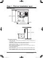
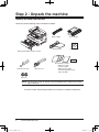
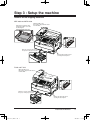
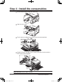
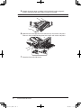
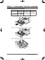
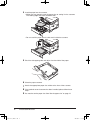
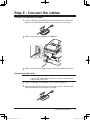
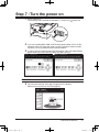
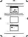
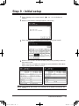
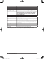
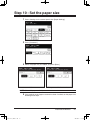
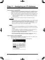
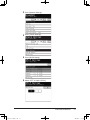
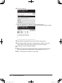
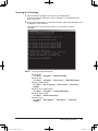
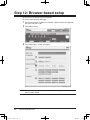
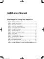
Installation Manual The steps to setup the machine Step 1 : Pick an installation spot..............................................1 Step 2 : Unpack the machine...................................................2 Step 3 : Setup the machine.....................................................3 Step 4 : Install the consumables..............................................5 Step 5 : Load paper into the cassette......................................7 Step 6 : Connect the cables.....................................................9 Step 7 : Turn the power on.....................................................11 Step 8 : Turn off the transport mode......................................12 Step 9 : Initial setup...............................................................13 Step 10 : Set the paper size..................................................15 Step 11 : Assigning an IP Address........................................16 Step 12: Browser-based setup..............................................20 Step 13: Setup e-mail server.................................................21 Step 14 : Installing drivers and OfficeBridge utilities.............22 Step 15 : Driver installation for local printing and scanning...22 Installation_Manual.indd 1 2007/04/27 12:11:21 Installation_Manual.indd 2 2007/04/27 12:11:21 Step 1 : Pick an installation spot Space requirement: 100 mm (40 inches) 872 mm 772 mm (344 inches) (304 inches) 50 mm (20 inches) 753 mm (297 inches) 50 mm (20 inches) 853 mm (337 inches) 100 mm (40 inches) 713 mm (181 inches) 813 mm (221 inches) The location should be: •Clean / Dust free — Dust build-up can damage your machine. (However, do not use a dust cover!) •In the open — Allow for adequate space around your machine. Be sure that you never cover the machine. Its vents must be able to “breathe.” • Away from direct sunlight — This helps avoid overheating. •Dry — Avoid any location where splatters or sprays (such as from a water fountain) could reach your machine. • Level, and vibration free • Near a phone jack — Your machine uses a standard (modular) telephone jack. •Near an AC power outlet — The AC power cord is about 6.5 feet (2.0 m) long when stretched to its limit. The power cord should never be stretched to its limit. Installation Manual Installation_Manual.indd 1 2007/04/27 12:11:22 Step 2 : Unpack the machine Remove all items from the box. Check that all the following items have been included. Drum cartridge Main unit with 500-sheet paper cassette Telephone line cable AC power cord Document tray Toner cartridge Installation CD Documentations & label MFP User's guide PC User's guide Quick reference guide Installation guide (this book) Paper size label . . . . . Ferrite core NOTE:The inclusion of the AC power cord and telephone line cable vary according to countries. Save the carton and packing material in case there’s a need for reshipment. Installation_Manual.indd Installation Manual 2 2007/04/27 12:11:22 Step 3 : Setup the machine Remove all the shipping materials MFX-2050 and MFX-1450: Remove the protective sheet between the platen cover and document glass. (MFX-2050, MFX-1450 only) Open the ADF cover, then remove the protective sheet from the ADF. Open the cassette and remove the spacer in the paper cassette. Remove the protective sheet covering the touch panel. F-565 and F-525: Open the ADF cover, then remove the protective sheet from the ADF. Open the cassette and remove the spacer in the paper cassette. Remove the protective sheet covering the touch panel. Installation Manual Installation_Manual.indd 3 2007/04/27 12:11:25 Attach the document tray Attach the document tray by inserting it into the appropriate holes, as shown below. Unlock the scanner (For MFX-2050, MFX-1450 only) IMPORTANT: In order to avoid damaging the unit, the machines scanner is locked prior to shipping. If you need to relocate the machine, lock the scanner prior to moving it. To lock the scanner, please use the reverse process of the instructions below. 1 Slide the scanner locking knob to the back until it clicks in the unlocking position. 2 Turn off the transport mode (see Step 8 “Turn off the transport mode,” page 12). Installation_Manual.indd Installation Manual 4 2007/04/27 12:11:25 Step 4 : Install the consumables 1 Pull the release lever to open the side cover. 2 Open the front cover. 3 Turn the toner cartridge locking lever to the left (unlock position). 4 Unpack the drum cartridge from its carton and slide it into the machine firmly until it locks into place. NOTE:DO NOT touch the drum surface. Installation Manual Installation_Manual.indd 5 2007/04/27 12:11:32 5 Unpack the starter toner cartridge, hold it with both hands and gently shake it to distribute the toner evenly inside the cartridge. NOTE:Do not touch the roller of the toner cartridge. 6 Slide the toner cartridge into the machine firmly until it locks into place. Then turn the cartridge locking lever to the right until it locks into place. 7 Close the front and side covers. Installation_Manual.indd Installation Manual 6 2007/04/27 12:11:35 Step 5 : Load paper into the cassette Acceptable paper sizes for the cassette: Region Paper size Paper type Quantity U.S. Letter, Legal, Half-letter Plain paper 500 sheets European and Asian countries A4, A5 , F4 (Weight: 20–24 lbs. (Weight: 20 lbs. 60–90g/m2) 60g/m2) 1 Pull the handle toward you to open the paper cassette. 2 Press the paper lifting plate down until it locks into position. 3 Adjust the rear paper guide to the desired paper length. Installation Manual Installation_Manual.indd 7 2007/04/27 12:11:35 4 Load the paper into the cassette. • Make sure you properly stack the paper prior to setting it in the cassette. The leading edge and sides should be even. • Do not stack the paper over the limit mark inside the cassette. 5 Pinch the side paper guide and adjust it to the width of the paper. 6 Close the paper cassette. 7 Attach the appropriate paper size sticker to the front of the cassette. 8 If the optional second cassette has been installed, please follow these steps. 9 You need to set the paper size. See “Set the paper size” on page 15. Installation_Manual.indd Installation Manual 8 2007/04/27 12:11:36 Step 6 : Connect the cables Connect the telephone line cable 1 Loop the telephone line cable and attach the ferrite core as shown. The telephone line cable loop should be near the connector of the cable. 2 Plug the telephone line cable into the LINE jack. PHO NE1 PHO NE2 LIN E 3 Plug the other end of the telephone line cable to the telephone wall jack. Connect the LAN cable NOTE: • A LAN cable is not supplied with the machine. • If you are not installing the machine on a network, please skip to “Connect the power cord”. 1 Prepare a 10BASE-T or 100BASE-Tx LAN cable (Category 5). 2 Loop the LAN cable and attach the ferrite core as shown. The LAN cable loop should be near the connector of the cable. Installation Manual Installation_Manual.indd 9 2007/04/27 12:11:38 3 Plug the LAN cable into the LAN connector. PHONE1 PHONE2 LINE 4 Plug the other end of the LAN cable into a 10Base-T/100Base-Tx Ethernet hub, or into the appropriate RJ-45 wall jack. Ethernet hub Connect the power cord 1 Plug the non-pronged end of the supplied AC power cord into the AC socket on the machine. PHONE1 PHONE2 LINE 2 Plug the pronged end into a properly grounded AC outlet. NOTE :The appearance of the plug and outlet differs according to the countries. 10 Installation_Manual.indd Installation Manual 10 2007/04/27 12:11:38 Step 7 : Turn the power on 1 Turn the power on. The markings are international standards: [ | ] means on, [ ] means off. 2 If you are installing MFX-2050 or MFX-1450, perform Step 8 “Turn off the transport mode” first (see next page). Once the transport mode has been turned off, you may procedure to the next procedure. 3 In some cases the following message will appear. If this message appears, please enter the current date and time, then press [Enter]. U.S. European and Asian countries NOTE:The calendar format may vary according to the countries. 4 The “Server Initializing” message will appear on the display. Please wait a few minutes until it disappears. Installation Manual Installation_Manual.indd 11 11 2007/04/27 12:11:39 NOTE:If a DHCP (Dynamic Host Configuration Protocol) server is not installed on your network or if you are not installing the machine on a network, the message will read “DHCP server did not respond“. You will need to turn off the DHCP server manually as described in “If your network is not using DHCP” on page 16. Step 8 : Turn off the transport mode (For MFX-2050/1450 only) 1 When the machine is turned on, the display shows the following message: 2 Press <Setting>, < >, <1>, <4> in this order. 3 Press [OFF], and then [Enter]. 4 Go back to page 11 Step 7 “Turn the power on” step 3. 12 Installation_Manual.indd Installation Manual 12 2007/04/27 12:11:39 Step 9 : Initial setup 1 Press <Setting> on the control panel, < >, <0>, <2> to initialize the memory. 2 When the confirmation message appears, press [Yes]. 3 Press <Setting> on the control panel and then press [User Install]. 4 When the first screen has been entered, press [Prev] or [Next] to move to the second screen. Select each item and adjust the setting(s) to your preference. After adjusting the setting, press [Enter] to save it. NOTE:“Time setting” and “Comm. Line” settings are not appear according to the country. Installation Manual Installation_Manual.indd 13 13 2007/04/27 12:11:39 Items Descriptions Language Select the language. Time Setting Set Daylight Setting Enter current date and time. * Select whether to activate the daylight saving feature. Broadcast Set the broadcast transmission option. If you select [ON], you can select two or more destinations from the address book at a transmission. If you select [OFF], the transmission will immediately start when you press a destination from the address book. Comm. Line * Select the line type: [Tone] or [Pulse]. Reception Mode Select the fax reception mode that best matches the machine usage. Dial Tone Detect Select whether to detect the dial tone before dialing or not. This will normally be set to [OFF]. TTI Enter/Edit Enter the name (or company name) to be shown at the top of the faxes sent from your machine. Up to three TTIs can be registered. Default TTI Select the TTI that will be used most often. TTI Number Enter the fax number of the machine. Time Zone Enter the time zone for e-mail transmission. *: “Time setting” and “Comm. Line” settings are not appear according to the country. 14 Installation_Manual.indd Installation Manual 14 2007/04/27 12:11:40 Step 10 : Set the paper size 1 Press <Setting> on the control panel, then [Paper Settings]. 2 Press [Cassette 1]. 3 Select the paper that you loaded, and press [Enter]. U.S. European and Asian countries NOTE:Selectable paper varies by countries. 4 If the optional second paper cassette has been installed, set the paper size following these steps. Installation Manual Installation_Manual.indd 15 15 2007/04/27 12:11:40 Step 11 : Assigning an IP Address If your network is using DHCP If a DHCP (Dynamic Host Configuration Protocol) server is installed on your network, the machine will automatically be assigned an IP address and Subnet Mask the first time the machine is turned on. According to the DHCP server setting, a Gateway address and DNS server address may be assigned as well. 1 To see the assigned IP address for your machine, print the “Network setting list”. by pressing <Setting> [List] [Network Settings] [Yes] on the control panel. 2 Go to “Verifying the IP settings” on page 19 and begin with step 2. IMPORTANT • Once the DHCP server has assigned the IP address to your machine, that IP address MUST be reserved within the specific DHCP scope. Failure to do so could result in failed operation when the IP address lease expires. • After an IP address is assigned to your machine, please turn DHCP to OFF. (For instruction, see step 1 and 2 of “IP Address,” below.) NOTE • You can view the assigned addresses on the TCP/IP setting menu display. • The IP address and Subnet Mask assigned from the DHCP server cannot be modified. • A “Gateway Address” and “DNS server address” will not be assigned if the primary and secondary address have already been registered. • If you are not utilizing a DHCP server, please turn DHCP to OFF and manually assign the IP address and Subnet Mask. • If you are not installing the machine on a network, please skip to “Step 15 : Driver installation for local printing and scanning,” on page 22. If your network is not using DHCP You should turn off the DHCP server setting. Then enter the IP address manually to install your machine on your network. 1 Press <Setting> on the control panel, then [Management]. 16 Installation_Manual.indd Installation Manual 16 2007/04/27 12:11:40 2 Press [Network Settings]. 3 Press [TCP/IP Settings]. 4 Press [DHCP Setting]. 5 Select “OFF” and press [Enter]. Installation Manual Installation_Manual.indd 17 17 2007/04/27 12:11:40 6 Press [IP Address]. 7 Enter the appropriate IP address using the numeric keys. Press the arrow keys to navigate the field. Press [Clear] to delete a number. 8 Press [Enter]. The display returns to the TCP/IP settings menu. 9 Press [Subnet Mask] and enter the appropriate IP address, then press [Enter]. Refer to the above steps on how to enter the IP address. 10If necessary, enter the gateway address. 11When you are finished, reboot the machine to activate the new settings. (Turn the machine off and after three or more seconds, turn it on.) 12Go to “Verifying the IP settings” on next page. 18 Installation_Manual.indd Installation Manual 18 2007/04/27 12:11:41 Verifying the IP settings 1 Print the network setting list to view the new configuration. To print the network settings list: Press <Settings>, [List], [Network Settings], then [Yes]. 2 At the command prompt on a network computer, type “ping” followed by the IP address of your machine. If the machine is active on the network, you will receive a replay. (Sample) NOTE: To run the command prompt: Windows 98: Click Start → Programs → MS-DOS Prompt Windows Me: Click Start → Programs → Accessories → MS-DOS Prompt Windows 2000 and XP: Click Start → ALL Programs → Accessories → Command Prompt Windows NT 4.0 Workstation: Click Start → Programs → Command Prompt Windows Server 2003: Click Start → Command Prompt Windows Vista: Click Start → All Programs → Accesarries → Command Prompt Installation Manual Installation_Manual.indd 19 19 2007/04/27 12:11:41 Step 12: Browser-based setup Your machine can be set up from a browser. To access the machine’s web page: 1 Type the machine’s IP address in the URL address field of your browser. (Ex. http://192.168.1.10/) 2 Click [Admin Tools]. 3 The “Admin Tools” screen will appear. NOTE:For more information, please see Chapter 4, “Using the Admin Tools,” in the PC User’s Guide. 20 Installation_Manual.indd Installation Manual 20 2007/04/27 12:11:41 Step 13: Setup e-mail server In order to use the e-mail and Internet fax function on your machine, the “SMTP/POP” settings and “E-mail Settings” must be setup. These settings can be configured using a Web Browser. NOTE:Please see “Network Configuration” in Chapter 4, “Using the Admin Tools,” in the PC User’s Guide. Installation Manual Installation_Manual.indd 21 21 2007/04/27 12:11:41 Step 14 : Installing drivers and OfficeBridge utilities To take full advantage of the features of your machine, install the OfficeBridge drivers and utility programs. For more information of the installation, please see “Installing OfficeBridge on your PC” in Chapter 1, “Getting Started,” in the PC User’s Guide. Step 15 : D river installation for local printing and scanning Install drivers to use the machine as a local printer and scanner. A USB cable is required to connect your machine to your computer. NOTE:For local installation, do not attach an USB cable while your machine and computer are turned on. Install the drivers first. For more information of local installation, please see the Printer and Scanner driver manual located in the “Manuals” folder on the CD supplied with the machine. 22 Installation_Manual.indd Installation Manual 22 2007/04/27 12:11:41