1
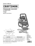
0M-17255
)perator's
Manual
.0 Amp
;c
i"
Model
No.
320.17255
DOUBLE
, CAUTION
Read,
Safety
Rules
and
this Manual
before
understand
and
follow
Operating
Instructions
using
this product.
ars, Roebuck
and Co.,
ffman Estates,
IL 60179 U.S.A.
;it our Craftsman
website:
www.craftsman.com
0M-17255
INSULATED
o WARRANTY
° SAFETY
o UNPACKING
° DESCRIPTION
° BLADE
INSTALLATION
o OPERATION
° ADJUSTMENTS
° MAINTENANCE
Warranty
..........................................................................
Page
2
Page
3
..........................................................
Pages
4 - 9
..........................................................
Pages
9 - 10
Pages
10-
Description
..................................................................
Blade
Installation
...........................................................
Pages
Page
11 - 13
13 - 15
Operation
Pages
16 - 25
Pages
26
Page
27
Accessories
..........................................................................
Repair
Parts ..........................................................................
Page
Pages
27
28 - 31
Sears
Back
Safety
Symbols
Safety
Instructions
Glossary
.............................................................
of Terms
Unpacking
....................................................................
....................................................................
Maintenance
.........................................................................
Troubleshooting
ONE
.....................................................................
Repair
Parts
Phone
Numbers
YEAR
FULL
WARRANTY
ON
.....................................
CRAFTSMAN
Cover
® PRODUCT
If this Craftsman
product
fails due to a defect
in material
or workmanship
within
one year from the date of purchase,
RETURN
IT TO THE NEAREST
SEARS
STORE
OR PARTS
AND
REPAIR
CENTER
OR OTHER
CRAFTSMAN
OUTLET
IN THE UNITED
STATES
FOR FREE
REPLACEMENT.
This warranty
bits or blades.
If this Craftsman
warranty
applies
does
not
product
for only
include
expendable
is used for commercial
90 days from the date
This warranty
gives you specific
legal rights,
rights,
which
vary from state to state.
Sears,
Roebuck
and Co., Hoffman
Estates,
SAVE
READ
parts
THESE
INSTRUCTIONS!
ALL INSTRUCTIONS!
2
and
such
as lamps,
batteries,
or rental purposes,
of purchase.
you
IL 60179
may
also
have
this
other
11
The purpose
of safety
symbols
is to attract
your attention
to possible
dangers.
The safety
symbols,
and the explanations
with them, deserve
your careful
attention
and understanding.
The symbol
warnings
DO NOT by themselves
eliminate
any danger.
The instructions
and warnings
they give are no substitutes
for proper
accident
prevention
measures.
Z_ WARNING:
BE SURE
to read and understand
all safety
instructions
in this
manual,
including
all safety
alert symbols
such as "DANGER",
"WARNING"
and
"CAUTION",
BEFORE
using this saw. Failure
to follow
all instructions
listed below
may result
in electric
shock,
fire and/or
serious
personal
injury.
SYMBOL
MEANING
SAFETY
CAUTION.
ALERT
May
SYMBOL:
be used
indicates
in conjunction
with
DANGER, WARNING,
other
symbols
OR
or pictographs.
DANGER:
Failure
to obey this safety
warning
WILL result
in death
or serious
injury to yourself
or to others.
Always
follow
the safety
precautions
to reduce
the risk of fire,
electric
shock
and personal
injury.
Failure
to obey this safety
warning
CAN result
in death
or
injury
to yourself
or to others.
Always
follow
the
safety
precautions
to reduce
the risk of fire, electric
shock
and personal
injury.
I Z_WARNING
I serious
I z_CAUTION
I injury
Failure
to obey this safety
warning
MAY result
in personal
to yourself
or others
or property
damage.
Always
follow
the safety
precautions
to reduce
the risk of fire,
electric
shock
and personal
injury.
DAMAGE
PREVENTION
AND INFORMATION
MESSAGES
These
inform user of important
information
and/or
instructions
that could lead to equipment
or other property
damage
if not followed.
Each message
is preceded
by the word
"NOTE:"
as in the example
below:
NOTE:
Equipment
not followed.
WEAR
YOUR
and/or
property
damage
may
result
if these
instructions
are
z_WARNING:
The operation
of any sabre
saw can result
in foreign
objects
being
thrown
into your eyes, which
can
result
in severe
eye damage.
Before
beginning
power tool
operation,
ALWAYS
wear safety
goggles
or safety
glasses
with side shield
and a full-face
shield
when
needed.
We recommend
a Wide Vision
Safety
Mask for use over
eyeglasses
or standard
safety
glasses
with side shield,
available
at Sears
Stores
or other
Craftsman
Outlets.
3
/ WARNING"
BE SURE
to read and understand
all instructions
in this
manual
before
using
this sabre
saw. Failure
to follow
all instructions
may
result
in hazardous
radiation
exposure,
electric
shock,
fire and/or
serious
personal
injury.
WORK
1. Keep
invite
AREA
SAFETY
your work
accidents.
area
clean
and
well
lit. Cluttered
workbenches
2. DO NOT operate
power
tools in explosive
atmospheres,
of flammable
liquids,
gases,
or dust. Power tools create
the dust or fumes.
3. Keep bystanders,
Distractions
can
4. Make
when
children
cause
you
your workshop
not in use.
childproof
5. MAKE
SURE
the work
there are no obstructions
PERSONAL
and visitors
to lose control.
with
while
padlocks
and
area has ample
that will interfere
operating
master
lighting
so you can
with safe operation
dark
areas
as in the presence
which may ignite
a power
switches.
tool.
Lock
tools
away
see the work and that
BEFORE
using your saw.
SAFETY
1. KNOW
your power
tool. Read the
applications
and limitations,
as well
tool.
2. STAY ALERT,
a power
tool.
3. DO NOT
A moment
personal
away
such
sparks
and
watch
what
use tool while
of inattention
injury.
you
operator's
manual
carefully.
Learn the saw's
as the specific
potential
hazards
related
to this
are doing
and
use
common
sense
when
operating
tired or under the influence
of drugs,
alcohol
or medication.
while operating
power tools may result in serious
4. DRESS
properly.
DO NOT wear loose clothing
or jewelry.
Pull back long hair.
Keep your hair, clothing,
and gloves
away from moving
parts. Loose
clothing,
or long
hair can be caught
in moving
parts. Air vents often cover
moving
parts and should
also be avoided.
5. AVOID
accidental
starting.
Be sure switch
is in "OFF"
position
before
plugging
in.
DO NOT carry tools with your finger
on the switch.
Carrying
tools with your finger
on the switch
or plugging
in tools that have the switch
in the "ON"
position
invites
accidents.
6. REMOVE
adjusting
that is left attached
7. Do not overreach.
and balance
enables
8. ALWAYS
It is safer
keys or blade wrenches
before
turning
to a rotating
part of the tool may result
Keep proper
footing
and balance
at all times.
Proper
better
control
of the tool in unexpected
situations.
SECURE
YOUR
than using your
9. USE SAFETY
EQUIPMENT.
shoes,
hard hat, or hearing
1 0. DO NOT USE
enables
better
the tool "ON".
A wrench
in personal
injury.
WORK.
Use clamps
hand and frees both
Always
protection
or a vise to hold
hands to operate
work
tool.
when
footing
practical.
wear eye protection.
Dust mask,
non-skid
must be used for appropriate
conditions.
ON A LADDER
or unstable
support.
Stable
control
of the tool in unexpected
situations.
4
footing
on a solid
safety
surface
TOOL
USE
AND
CARE
z WARNING-
SAFETY
BE
operating
this
electric
shock,
SURE
saw. Failure
fire and/or
to read
and
understand
all instructions
to follow
all instructions
serious
personal
injury.
or other
practical
ways
Holding
the work by hand
listed
before
may
result
in
1.
ALWAYS
use clamps
to a stable
platform.
lead to loss of control.
2.
DO NOT force the tool. Use the correct
The correct
tool and blade will do the job
it is designed.
3.
DO NOT
controlled
4.
DISCONNECT
the plug
from
the power
source
before
making
any adjustments,
changing
accessories
or storing
the tool.
Such preventive
safety
measures
reduce
the risk of starting
the tool accidentally.
5.
NEVER
comes
6.
STORE
idle tools
out of the reach
of children
are dangerous
in the hands
of untrained
users.
7.
MAINTAIN
tools with
8.
CHECK
for misalignment
or binding
of moving
parts,
breakage
of parts,
other condition
that may affect the tool's operation.
If damaged,
have the tool
before
using.
Many
accidents
are caused
by poorly
maintained
tools.
9.
USE ONLY accessories
suitable
for one tool may
use the tool if switch
does
with the switch
is dangerous
leave the tool running.
to a complete
stop.
tools
with
sharp cutting
ELECTRICAL
and support
the workpiece
your body is unstable
and may
tool and blade
better
and safer
for your application.
at the rate for which
not turn
it "On"
or "Off".
and must be repaired.
ALWAYS
turn
it off.
and
DO NOT
other
Any
leave
untrained
cutting
tools
sharp
and clean.
less likely to bind and are easier
tool
the
that
tool
cannot
until
persons.
Properly
to control.
that are recommended
for this tool. Accessories
become
hazardous
when used on another
tool.
be
it
Tools
maintained
and any
serviced
that
may
be
SAFETY
z WARNING:
installing
care.
Keep
edges
are
to secure
or against
below
Do
or removing
not
the
permit
fingers
plug from the
to touch
outlet.
the
terminals
of plug
when
1. Double
insulated
tools are equipped
with a polarized
plug (one blade is wider
than
the other). This plug will fit in a polarized
outlet
only one way. If the plug does not fit
fully in the outlet, reverse
the plug. If it still does not fit, contact
a qualified
electrician
to
install
a polarized
outlet.
Do not change
the plug in any way.
2. Double
insulation
[] eliminates
the need for the three-wire
grounded
power
cord
and grounded
power supply
system.
Applicable
only to Class
II (double-insulated)
This
sabre
saw is a double
insulated
tool.
/ WARNING:
precautions
when
Double
operating
insulation
DOES
this tool.
5
NOT
take
the
place
of normal
tools.
safety
•
"
ELECTRICAL
SAFETY
O
•
cont.
3. BEFORE
plugging
in the tool, BE SURE
that the outlet
voltage
supplied
is within
the voltage
marked
on the tool's
data plate.
DO NOT use "AC only" rated tools
with a DO power
supply.
4. AVOID
body
contact
with grounded
surfaces,
such as pipes,
radiators,
ranges
and refrigerators.
There
is an increased
risk of electric
shock
if your body
is grounded.
5. DO NOT expose
power
tools
to rain or wet conditions
or use power
tools
in wet or damp
locations.
Water
entering
a power
tool will increase
the risk
of electric
shock.
6. INSPECT
tool
cords
for damage.
Have
damaged
tool cords
repaired
at a Sears
Service
Center.
BE SURE
to stay constantly
aware
of the cord location
and keep
it well away
from the moving
blade.
7. DO NOT abuse
the cord.
NEVER
use the cord to carry
the tool
by or to pull
the plug from
the outlet.
Keep cord away
from
heat, oil, sharp
edges
or moving
parts.
Replace
damaged
cords
immediately.
Damaged
cords
increase
the risk of
electric
shock.
EXTENSION
CORDS
Use a proper
extension
cord.
ONLY
use cords
listed by Underwriters
Laboratories
(UL). Other
extension
cords
can cause
a drop in line voltage,
resulting
in a loss of power
and overheating
of tool. For this tool an AWG
(American
Wire
Gauge)
size of at least
14-gauge
is recommended
for an extension
cord of 25-ft. or
less in length.
Use 12-gauge
for an extension
cord of 50-ft.
Extension
cords
100-ft.
or longer
are not recommended.
Remember,
a smaller
wire gauge
size has
greater
capacity
than
a larger
number
(14-gauge
wire has more capacity
than
16-gauge
wire;
12-gauge
wire has more capacity
than 14-gauge).
When
in doubt
use the smaller
number.
When
operating
a power
tool outdoors,
use an outdoor
extension
cord marked
"W-A"
or "W". These
cords
are rated for outdoor
use and
reduce
the risk of electric
shock.
Z_ CAUTION:
Keep
the cord so that it will
while
you are working
the
extension
cord
not get caught
on
with a power
tool.
lumber,
z WARNING:
immediately.
area could
clear
of the
tools
working
or other
area.
Position
obstructions
Check
extension
cords
before
each use. If damaged
replace
Never
use tool with a damaged
cord since touching
the damaged
cause
electrical
shock,
resulting
in serious
injury.
6
SAFETY
SYMBOLS
FOR
YOUR
TOOL
The label on your
tool may include
V .......................................................................
A ......................................................................
Hz ....................................................................
W .....................................................................
min ..................................................................
the
following
Volts
Amps
Hertz
Watts
Minutes
symbols.
,-,,_,....................................................................
...................................................................
Alternating
current
Direct current
no ....................................................................
[] .....................................................................
.../min ..............................................................
Z_- ....................................................................
No-load
speed
Class II construction,
Double
Insulated
Revolutions
or Strokes per minute
Indicates
danger,
warning
or caution.
It means
attention!
Your safety
is involved.
SERVICE
SAFETY
1. If any part of this saw is missing
or should
break,
bend,
or fail in any way;
or should
any electrical
component
fail to perform
properly:
SHUT
OFF
the power
switch
and remove
the saw plug from the power
source
and have
the missing,
damaged
or failed parts
replaced
BEFORE
resuming
operation.
2. Tool service
must be performed
Service
or maintenance
performed
a risk of injury.
only
at a Sears
Parts
and Repair
Center.
by unqualified
personnel
could result
in
3. When
servicing
a tool, use only identical
replacement
parts.
Follow
instructions
in the maintenance
section
of this manual.
Use of unauthorized
parts or failure
to follow
maintenance
instructions
may create a risk of electric
shock
or injury.
SAFETY
hand
blade
z_
RULES
FOR
SABRE
SAWS
Keep hands away
on the auxiliary
handle
or motor
cannot
cut them.
CAUTION:
Blades
coast
i. KEEP
your body positioned
with the saw blade.
_>.DO NOT reach
saw is cutting.
under
the
from cutting
area and blade. Keep
housing.
If both hands are holding
after
saw
to either
workpiece.
side
The
is switched
of the
blade
saw
extends
3. DO NOT touch
the blade or the workpiece
immediately
be extremely
hot and could
burn your skin.
L DO
NOT
cut
an oversized
the
blade
off
blade
and
not
in direct
under
the
workpiece
after
operation;
line
when
they
may
workpiece.
_. CHECK
for the proper
clearance
under
the workpiece
blade
will not strike
the workbench
or material
under
;. MAKE
SURE
is turned
on.
your second
the saw, the
is not
contacting
the
7
workpiece
before
cutting
the workpiece.
before
the
so that
switch
the
SAFETY
RULES
FOR
SABRE
SAWS
cont.
7. HOLD
TOOL
by insulated
gripping
surfaces
(handles)
when
performing
an
operation
where
the cutting
tool may contact
hidden
wiring
or its own cord.
Contact
with a "live" wire will make the exposed
metal
parts of the tool "live" and
shock
the operator.
8. SECURE
or across
causing
MATERIAL
before
your
legs.
Small
loss of control.
9. When
ripping,
the accuracy
cutting.
Never
or thin
material
ALWAYS
USE a rip
of the cut and reduces
10. NEVER
cut more
than
one
workpiece
on the worktable
11. AVOID
cause
awkward
operations
your
hand
to move
reach
fence
or straight
the chance
of the
piece
at a time.
at a time.
DO
and hand
positions
into the blade.
path
of the
guide.
binding.
STACK
where
This
more
a sudden
improves
than
slip
one
could
13.
BLADE
GUIDE
ROLLERS
must support
the blade when cutting.
The rollers
must
rest against
the back edge of blade.
THE ONLY cutting
operation
when
rollers
DO
NOT support
the blade
is the scrolling
mode.
WHEN
SCROLLING
the blade must
swivel
as it is guided
to follow
scroll
patterns.
ALWAYS
move the base back and
blade
guide
up and back away from blade
in scrolling
mode.
cancer,
are:
cutting
NOT
edge
blade
NEVER
WARNING:
the
a workpiece
in your
hand
flex or vibrate
with
the blade,
12.
to cause
chemicals
into
hold
may
blade.
Use of this tool can generate
dust containing
birth defects
or other reproductive
harm.
Some
- Lead from lead-based
- Crystalline
silica from
° Arsenic
and chromium,
paints.
bricks
and cement
from chemically
and other masonry
treated
lumber.
chemicals
examples
known
of these
products.
Your
risk from these
exposures
varies,
depending
upon
how often
you do this
type
of work. To reduce
your exposure
to these
chemicals:
o Work in a well-ventilated
area.
- Work with approved
safety
equipment,
such as those dust masks
that are specially
designed
to filter out microscopic
particles.
Avoid
prolonged
contact
with dust from
and other
construction
activities.
Wear
areas with
soap and water.
Allowing
dust to get into your mouth,
eyes,
of harmful
chemicals.
power
sanding,
sawing,
protective
clothing
and
or lay on the skin
may
grinding,
drilling
wash
exposed
promote
absorption
WARNING:
Use of this tool can generate
and/or
disburse
dust, which
may cause
serious
and permanent
respiratory
or other injury.
Always
use
NIOSH/OSHA
approved
respiratory
protection
appropriate
for the dust
exposure.
Direct
particles
away
from
face and body.
8
ADDITIONAL
RULES
WARNING:
FOR SAFE OPERATION
BE
SURE
to follow
all instructions
serious
personal
injury.
to read
listed
and
below
understand
may
result
all instructions.
in electric
Failure
shock,
fire
and/or
1.
Know
your power
tool. Read operator's
manual
carefully.
Learn the applications
and limitations,
as well as the specific
potential
hazards
related
to this tool. Following
this rule will reduce
the risk of electric
shock,
fire or serious
injury.
2.
ALWAYS
eyeglasses
3.
PROTECT
4.
PROTECT
your
hearing.
Wear appropriate
personal
Under
some
conditions
noise from this product
may
5.
ALL VISTORS
AND
BYSTANDERS
operator
of the saw wears.
6.
INSPECT
nearest
7.
ALWAYS
check
the tool for damaged
parts.
Before
further
use of the tool, a guard
or other part that is damaged
should
be carefully
checked
to determine
if it will operate
properly
and perform
its intended
function.
Check
for misalignment
or binding
of moving
parts,
breakage
of parts,
and any other condition
that may affect
the tool's operation.
A guard
or other part that is damaged
should
be properly
repaired
or replaced
at a
Sears
Service
Center.
8.
INSPECT
9.
SAVE THESE
INSTRUCTIONS.
others
who may use this tool.
these
instructions
also.
wear
safety
have only
your
the
Sears
and
glasses
or eye
impact-resistant
lungs.
Wear
a face
shields
lenses;
mask
or dust
MUST
wear
tool cords
periodically
and
Service
Center.
BE AWARE
remove
all nails
from
when
using
they are NOT
distance
that
the
saw
blade
A cutting
Bevel
A cutting
hearing
contribute
the
same
lumber
before
tooth
is bent
can
operation
is dusty.
protection
to hearing
during
loss.
safety
equipment
(or set)
be varied,
that
repaired
operation
made
against
the
grain
and
tool,
as it applies
outward
usually
use them to instruct
make
sure they have
to the
workpiece.
from
the
face
of the
from
0 to 3000
of the
work
made
with
the
blade
at any
9
angle
between
piece.
+45 ° to the
blade.
strokes
Cut
operation
the
at your
cut
or shaping
use.
sawing.
Refer
to them frequently
If someone
borrows
this
Strokes
per Minute
or Stroke
Speed
The blade
speed
of a sabre saw, which
per minute.
Cross
if the
if damaged
have them
of the cord
location.
Saw
BladePath
The area over, under,
behind
or in front of the blade,
That area which
will be or has been cut by the blade.
Set
The
mask
this saw. Everyday
safety
glasses.
base.
Ripping
A cutting
or Rip Cut
operation
along
Freehand
the
length
of the
workpiece.
Cut
Performing
a cut without
using a fence,
miter gauge,
fixture,
proper
device
to keep the workpiece
from twisting
or moving
Orbital
Sawing
In addition
to the up and down
which
thrusts
the blade
forward
speed
over conventional
sabre
Scrolling
Allows
the
blade
to swivel
Through
Sawing
Any cutting
operation
of the workpiece.
for
where
movement
of a sabre
on the cutting
stroke
saws.
intricate
the
pattern
blade
work clamp,
or other
during
the cut.
saw's
blade,
and greatly
there
is orbital action
increases
the cutting
cutting.
extends
completely
through
the
thickness
produced
by the
Kerf
The material
removed
by the blade
in a non-through
or partial
cut.
Workpiece
or Material
The item on which
the
are commonly
referred
in a through
cut or the
cutting
operation
is being
done.
to as faces,
ends and edges.
The
slot
surfaces
blade
of a workpiece
Gum
A sticky,
sap-based
residue
Resin
A sticky,
sap-based
substance
WARNING:
Your
when
you are assembling
blades,
cleaning
or when
accidental
starting,
which
saw
2.
The Bevel
Assist
of the case.
handle
3.
The
is attached
4.
Carefully
Adapter
lift the
is force-fitted
saw
out
products.
has
hardened.
should
NEVER
be connected
to the
power
source
parts,
making
adjustments,
installing
or removing
it is not in use. Disconnecting
the saw will prevent
could
cause
serious
personal
injury.
The
Vac
Guide
wood
that
1.
• 5.
Edge
from
with
of the
into
the
3 Blades
to the
saw.
case
and
top
of the
stored
place
storage/carrying
inside
is also
on a stable
flat
case.
force-fitted
into
the
surface.
Inspect
the saw carefully
to make
sure that no breakage
or damage
has occurred
during
shipping.
If any of the items mentioned
are missing
(refer to illustration
on page
11) return the saw to your nearest
Sears
store or Craftsman
outlet to
have the saw replaced.
10
top
WARNING:
in the
Failure
If any parts
are broken
or missing,
DO NOT attempt
power
cord or operate
saw until the broken
or missing
parts
are
to do so could
result
in possible
serious
injury.
PARTS
to, plug
replaced.
LIST
2. Bevel Assist Handle
with 3 Blades stored
=ig. 1
3. Edge
Guide
(stored
in case)
l_l
r-
II
5. Operator's
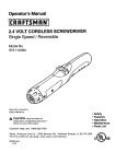
_NOWYOUR
SABRE
SAW
NOTE:
Before
attempting
operating
features
and
)ur sabre
saw has
__0-velt, 60-Hz
AC
rect current
(DC).
rerheat.
If the saw
NLY outlet,
check
o adapter
needed).
1is Sabre
5.0 Amp,
Saw
the
Variable
following
= i
Manual
familiarize
yourself
with
all of the
Speed
Action
features:
Motor,
800
by the
The
to 3000
speed
control
lever
SCROLLING
360 ° blade
rotation
using
normal
up and down blade
motion.
NO
2.
SMOOTH
3.
LOW
4.
MEDIUM
for
5.
FAST
maximum
minimal
for cutting
splintering,
most
cutting
Blade
Guide
Support
for faster
cutting.
normal
metals,
plastics,
orbital
Rollers
low
SPM
dial
1.
for
I
Adapter
to saw)
2)
to use your saw,
safety
requirements.
is controlled
Scrolling/Orbital
4. Vacuum
(attached
a precision
built electric
motor
and it should
only be connected
to a
ONLY power
supply
(normal
household
current).
DO NOT operate
on
This large voltage
drop will cause
a loss of power
and the motor
will
does not operate
when
plugged
into a correct
120-volt,
60-Hz AC
the power
supply.
This saw has an 8-ft., 2-wire
power
cord
has
Variable
Speed
switch
handle.
(Fig.
inside
provides
located
regulates
scrolling
orbital
orbital
11
(no-load
on the top front
the 5 cutting
speed).
of the trigger
modes
of the saw.
blade
motion.
NO
orbital
action.
action.
medium
use for
added
per minute
knob,
action.
up and down
hardboard,
action,
strokes
fast
blade
orbital
cutting
action.
in plywood,
control.15/16-inch
softwoods.
blade
stroke
This
following
Sabre
Saw
has
5.
Durable
Base
glides
6.
Bevel
7.
Bevel
Assist
Handle
use for maximum
control
when
bevel cutting.
either side of the saw. Stores
under
the saw or in case. Conveniently
blades,
2 wood
and 1 metal cutting
blade
included.
Also has built-in
adjust
base for scroll cutting
and bevel cutting.
8.
Quick
Cutting
blade
the
smoothly
Capacity
over
0 ° to
changes
with
features
cont.:
workpiece.
45 ° left
and
Bevel
11.
Soft-grip
12.
Extended
13.
Clear
14.
2-way
sawdust
removal:
1. Blower
position
blows
2. Vacuum
position
for hook-up
to wet/dry
vac, sold
15.
Includes
16.
Permanently
17.
Durable
machined
18.
Durable
tool from
cast aluminum
damage.
19.
Includes
Fig.
Front
Chip
edge
switch
guide,
ideal
for fast,
gearing
power
saw
is plugged
maximum
lock-on
repetitive
bearings
for longer
and
Attaches
on
holds extra
hex key tip to
into
control,
power
source.
balance.
button.
case
for
lasting
easy
Knob
debris away
separately.
power
resistant
carrying
Speed
from
work
cutting
long
life.
line.
cutting.
for smooth
high-impact
Variable
Control
for
straight
ball
2
Scrolling
adjustments.
Guard
100%
resistant
when
handle
with
Shield/Blade
lubricated
impact
cutting
area.
light
is green
designed
trigger
easy
no tools.
LED Worklight
illuminates
"Live
Tool Indicator"
LED
length
for
right.
9.
10.
ergonomically
scale
operation,
transmission.
housing
and
and
handle
protect
storage.
Dial
Power Lock
On Button
On/Off
er Switch
"Live Tool Indicator"
Light
8-ft.
,r Cord
Scrolling/
Orbit
Control
LED
Workli
Bevel
Assist
Handle
blades
/ Blower
Tool-less
Change
Blade
Holder
attaches to either
side of saw
Clear
Chip
Shield/Blade
Guard
Ejection
Blade
Plate
Blade
Rollers
Locking
Knob
for Edge Guide
Switch
Bevel Assist
Edge Guide
12
Handle Mounting
Mounting
Slot
Hole
Chute
5.0
Rating
No
Load
Speed
Input
Bevel
Cutting
Blade
Stroke
Angle
Range
Amps
800-3000
SPM
120-volts,
60-Hz
0 ° to 45 ° left and
per
minute)
AC
right
15/16-in.
Cutting
Depth
in Wood
3 3/8-in.
Cutting
Depth
in Steel
1/4-in.
Blade
(strokes
Storage
In The
Bevel
Assist
Handle
Your sabre
saw comes
with 1 metal cutting
and 2 wood cutting
blades.
The blades
are
stored
in the Bevel Assist
Handle
under
the
(6mm)
(Fig.
Fig.
(85ram)
3)
3
_ap. Unscrew
the cap on the handle
and
ocate
the blade
storage
with 3 blades.
:_emember
to always
use the proper
dade
for the material
being
cut. Always
hake sure the cap is on securely
before
Jsing the handle
on the saw, when
bevel
'utting,
or when storing
the handle
on the
;aw while operating
it.
"OOL-LESS
BLADE
INSTALLATION
bol-less
blade
change
allows
you
asily without
the use of additional
I. Unplug
the
(Figs.
to remove
tools.
and
4, 5 and
replace
6)
the
saw
blade
quickly
and
saw.
WARNING:
blades
or making
accidental
starting
ALWAYS
unplug
saw
from
the
power
any adjustments.
Failure
to unplug
which can cause
serious
personal
source
the saw
injury.
before
could
changing
result
in
NOTE:
When
installing
or removing
the cutting
blade from
the saw, always
have
the scrolling/orbit
control
lever in the SMOOTH
position.
If you have the lever in the
SCROLLING
position,
the blade holder
assembly
will keep turning
and you won't
be able to insert or remove
the blade.
• Raise
up the clear chip shield,
lift one side out of its mounting
slot, and remove
the
shield from the saw (see Fig. 4). Apply
a little force when
lifting and removing
the shield
from the saw.
• Turn
the
saw
upside
down
so you
have
access
13
to the
blade
holder
assembly.
TOOL-LESS
cont. (Figs.
.
5.
BLADE INSTALLATION
4, 5 and 6)
Rotate
the "red" cover
on the blade
holder
assembly
counterclockwise
about
a quarter
turn and hold it in this position
while
inserting
a blade
into the slot of the
blade
holder
(see Fig. 5). The teeth of the
blade
should
be facing
to the front and
point up (when
saw is right side up, in
cutting
position),
and the back of the
blade
must rest in the groove
of the
blade
guide
rollers
(see Fig. 6).
Release
blade
the
blade
holder
to lock
the
in place.
6.
Pull down
the blade
7.
Attach
the clear chip shield
into its
mounting
slots and snap the shield
down to its proper
position.
Fig.
on the blade
to make
sure
is securely
locked
in place.
6
Fig.
Blade
guide
rollers
support
the blade
when cutting
in all
cutting
modes
except
scrolling.
5
®
®
Blade
NOTE:
For
use
Blade
with
Guide
Rollers
both
"T"
and
"U"
shanked
blades.
/iX, CAUTION"
Once the blade
is installed
in the saw, it is always
exposed.
There
is no lower
blade
guard.
Use caution
when
handling
the saw so that the
blade
does
not catch
clothing,
skin, etc. Each time you set the saw down
take
care not to bend the blade.
Always
set saw down
on its side when
blade
is
installed.
ALWAYS
remove
blade
when
saw is not being
used.
14
=1 I"-)ii'i,..z.] ,I
REMOVING
1.
THE
Unplug
BLADE
the saw.
Z_ WARNING"
blades
or
accidental
I
ALWAYS
making
starting
Follow
3.
Oarefully
remove
4.
Reattach
the
Fig.
When
6 and
1 through
the
clear
blade
your
and
saw,
guide
cutting
operation
the saw is in the
blade
the
snap
before
the saw
injury.
installation
it down
ALWAYS
source
(see
changing
could
result
in
pages
13 and
14).
blade).
to its proper
remove
scrolling,
The
blade
rollers
must
where
scrolling
the
blade
guide
rest
the blade
mode.
must
rollers
the
support
against
the
guide
rollers
swivel
position.
cutting
the
back
blade
edge
do
not
as it is guided
ALWAYS
move
the base back and blade
guide
blade
when
operating
in the scrolling
mode.
Fig.
power
Failure
to unplug
serious
personal
(or change
shield
the
I
blade.
7
blade
When
from
4 on the tool-less
chip
storing
/_ CAUTION:
The
saw
any adjustments.
which
can cause
2.
NOTE:
steps
unplug
rollers
when
of the
support
to follow
up and
cutting.
blade.
the
THE
blade
the
scroll
back
away
ONLY
is when
pattern.
from
the
Fig. 7
6
Blade
guide
rollers
support
the blade
when cutting
in all
cutting
modes
except
scrolling.
Blade
guide
rollers
up and back
away from blade
when operating
in the scrolling
mode.
®
t==ff
k====J k=Z
®
Blade
Blade
Guide
Rollers
Blade
15
Blade
Guide
Rollers
LED WORKLIGHT
AND "LIVE
TOOL
INDICATOR"
LED
LED
LIGHT
(Fig.
8)
WORKLIGHT
Your sabre
saw has an LED worklight
that
turns
"ON" automatically
when
the saw is
plugged
into a power
source.
The light helps
provide
easy visibility
of the cutting
line.
Fig. 9
I
"LIVE
TOOL
INDICATOR"
LED
LIGHT
(Fig.
9)
Your saw has a "Live Tool Indicator"
green
LED light
that turns
"ON" automatically
when
the saw is plugged
into a power
source.
The light is located
on both sides
of the base of the trigger
switch
handle
near the body
the saw.
POWER
ON-OFF
TRIGGER
SWITCH
and
POWER
of
"LOCK-ON"
BUTTON
(Fig.
10)
1. Connect
the plug of your saw to
a standard
household
power
outlet.
2. Start the tool by squeezing
the
on/off
trigger
switch
(see Fig. 10).
3. To stop the tool,
trigger
switch.
release
the
on/off
4. To lock the on/off
trigger
switch
in
the "on" position,
press
trigger
switch
and while
holding
it "on",
press
in the lock-on
button,
located
on the left side of the
handle
(see Fig. 10).
Trigger Switch
Lock-on Button
5. The power
lock-on
button
allows
the
operator
to keep the sabre
saw
running
without
squeezing
the trigger
switch.
This is useful
for continuous
sawing
applications.
6. To release
the power
lock-on
press
and release
the trigger
This will turn the tool off.
/_
trigger
WARNING"
switch
Fig.
button,
switch.
If the lock-on
button
cannot
be released.
is continuously
16
being
depressed,
the
10
ADJUSTING
(Fig. 1.1 and
THE
1 la)
CUTTING
SPEED
WITH
THE
VARIABLE
The variable
speed
feature
of this saw allows
you to match
to the material
being
cut, enhancing
the overall
performance
to save the blades
from
undue
wear.
The speeds
by adjusting
can
the
The speed
dial
number
"6" the
The proper
workpiece
is numbered
fastest
speed
"1" through
(see Fig.
"6", with number
11 and 11 a).
for denser
you to cut
"1" the
slowest
speed
helping
Fig.
to be cut
Number
speed
speed,
and
of the
scroll
pattern.
and faster
speeds
faster,
but blade
can help you pick the proper
speed.
Remember
blade
for the cutting
application
and the material
Wood
Mild
materials
workpieces
11
Workpiece
the proper
cutting
of your saw and
will differ
depending
on the type and thickness
you are straight
cutting
or following
an intricate
rule, slower
speeds
are
High speeds
will allow
The following
chart
the proper
cutting
Fig.
DIAL
be adjusted
from 800 to 3000
SPM (strokes
per minute)
no-load
variable
speed
dial located
on top of the trigger
switch
handle.
blade
speed
and whether
As a general
soft materials.
be reduced.
SPEED
are for
life will
to ALWAYS
use
you are cutting.
11a
on Variable
Speed
Dial
5 - 6
steel
Stainless
2 - 5
steel
3 - 4
Aluminum
3 - 6
Plastics
1 - 4
17
•
.
•
.
.
SCROLLING
AND
The scrolling/orbital
The first 2 modes,
of a sabre saw.
ORBITAL
ACTION
(Fig.
12)
action control lever regulates the 5 cutting modes of the saw (see Fig. 13).
SCROLLING
AND SMOOTH,
produce the normal up and down blade action
The next 3 modes,
LOW, MEDIUM
AND FAST, produce
the orbital blade action. The orbital blade
action thrusts
the blade forward
on the cutting stroke (see Fig. 14), and greatly
increases
the
cutting speed over the normal up and down blade action.
The SCROLLING
and SMOOTH
settings
with the up and down blade action and the LOW
setting
with the least aggressive
orbital action are the ideal modes
for cutting
harder materials.
To increase
the orbital action,
turn the control
lever to FAST, and to decrease
the orbital action
turn the control
lever to MEDIUM
or LOW. The orbital action modes will produce
rougher finished
cuts, but will cut faster. When
minimal
splintering
is needed,
the SMOOTH
setting
position
should
be used for the normal
up and down blade motion
with NO orbital action.
ALWAYS
test
the cutting
modes
on a piece
of scrap
material
before
making
your
finished
cuts.
NOTE: Select the right blade for your cutting
application.
Blades
are available
for scroll
cutting,
fine woodcutting,
medium
and fast woodcutting,
and fast metal or smooth
metal
cutting.
A general
guide to use when selecting
a blade is, the more teeth per inch on the
blade, the smoother
the cuts, and the less teeth per inch on the blade the faster and
rougher
the cuts.
See
page
29,
ACCESSORIES,
for more
information
on selecting
the
1. SCROLLING
- This mode
allows
360 ° blade
rotation
using
the scrolling
knob.
In this mode
there
is no orbital
action.
Use with scroll
blade
to cut intricate
scroll
with normal
up and
right
blade
for the
job.
r'-'lrt
_"
II/
Fig. 12
patterns
in all materials
down
blade
motion.
2. SMOOTH
- This mode
is ideal for cutting
all
materials
with normal
up and down
blade
motion
with minimal
splintering.
In this mode,
there
is no orbital
action.
Use this mode
for
cutting
hardwoods,
mild steel, soft and hard
materials
with fine wood
cutting
and smooth
metal
cutting
blades.
3. LOW - Use this mode for cutting
most
plastics
and hardwoods,
with a slightly
aggressive
orbital
action.
4. MEDIUM
aggressive
5. FAST
softer
Choose
normal
- Use this mode
for
orbital
action
than
- For maximum
materials.
orbital
metal,
cutting
most metal,
the LOW mode.
action
and
the
plastics
fastest
and
cutting
hardwoods
in plywood,
the SCROLLING
or SMOOTH
settings
with the scrolling/orbital
up and down
blade
motion.
(See Fig. 13, Positions
1 and 2).
Choose
the LOW or MEDIUM
(See
Fig. 13, Positions
3 and
Choose
the
blade
action
FAST
(See
settings
4).
setting
for the fastest,
Fig. 13, Position
5).
for the
most
18
least
aggressive
aggressive
cutting
orbital
with
with
soft
woods
control
blade
a more
lever
actions
maximum
orbital
and
for
SCROLLING
AND
ORBITAL
2
Reduced
splintering
SMOOTH
in
all materials.
Use fine wood
blade, 20 teeth
per inch, or
smooth
metal
blade, 36 teeth
per inch.
cont.
Position
3
LOW
Low orbital
action in metal,
plastics,
hardwoods.
Use blades
for
wood and metal
cutting
with
10-12 teeth
per inch.
Position
1
SCROLLING
360 ° blade
rotation
in
all materials.
Use scroll
blade, 20 teeth
per inch.
Position
ACTION
Position
5
FAST
For maximum
orbital action
and the fastest
cutting
in
plywood,
soft
woods
and
softer
materials
such as
wallboard.
Use wood,
metal and
wallboard
cutting
blades
with
6, 8 12 teeth
per inch.
Position
4
MEDIUM
Medium
orbital
action in metal,
plastics,
hardwoods.
Use wood
and metal
cutting
blades
with 10-12 teeth
per inch.
f
!
Fig. 13
NOTE:
In order
to reach
full orbital
action,
the blade
MUST
BE FACING
STRAIGHT
FORWARD
and the back of the blade
must rest in the groove
of the
guide
rollers.
The base must
be all the way in the forward
position.
Orbital
action
is not observable
when
the saw is free-running.
The saw must be cutting
for orbital
action
to occur.
The speed
of cut is easier
to see in thicker
materials.
ADJUSTING
/ MOVING
FOR SCROLLING
(Fig.
NOTE:
of the
freely
In the
up and
position
Fig.
THE
BASE
14, 15 and
AND
16)
BLADE
GUIDE
ROLLERS
The blade
guide
rollers
must support
the blade
in all cutting
operations
saw except
when
scrolling.
When
scrolling,
the blade
should
rotate
(swivel)
and should
not come
into contact
with the blade
guide
rollers.
scrolling
mode
always
move
the base back and the blade
guide
rollers
away
from the blade.
The blade
is released
to swivel
in the SCROLLING
and if the blade
is held with the guide
rollers
it could
bend
and break.
Fig.
14
15
Blade
guide
rollers
up and back
away from blade
when operating
in the scrolling
mode.
Blade
guide
rollers
support
the blade when
cutting
in all
cutting
modes
except
scrolling.
®
®
¢==ff
®
®
Blade
Blade
Guide
Rollers
Blade
19
Blade
Guide
Rollers
ADJUSTING
/ MOVING
THE
BASE
AND
FOR SCROLLING
cont.
(Fig. 14, 15 and
1. Unplug
BLADE
16)
GUIDE
ROLLERS
the saw.
//_ WARNING"
ALWAYS
unplug saw from
or attaching
accessories.
any adjustments
2. Move
the
"Scrolling"
3. Remove
Scrolling/Orbit
position.
the
blade,
control
lever
the
page
source
BEFORE
making
to
Fig.
(see
power
16
15).
4. Use the bevel
assist
handle's
built in
hex key tip to loosen
the hex screw
in the base of the saw (see Fig. 16).
5. With the base
loosened,
push the base
back as far as it will go, then push up
and back
on the blade
guide
rollers
so
they move
away
from the blade
position
in the blade
holder
(see Fig. 15).
6. Re-tighten
the
7. Install
the
blade,
8. Make
away
sure
from
the
the
hex
screw
(see
blade
blade
in the
Page
guide
(See
SCROLLING
CONTROL
KNOB
FEATURE
(Fig.
base.
15).
rollers
are
Fig. 15).
17)
Fig.
17
The scrolling
feature
allows
the blade
to be
rotated
360 ° . It is ideal for cutting
curves,
designs
and detailed
pattern
work.
1. To engage
the scrolling
move
the Scrolling/Orbit
Lever
to the SCROLLING
2. Grasp
the scrolling
(see Fig. 17).
function,
Control
position.
control
knob
3. The scrolling
control
knob can
be rotated
360 ° to the left or
right while
guiding
the
follow
intricate
cutting
NOTE: The blade
the Scrolling/Orbit
saw to
lines.
can be locked
in any scrolling
position
within
Control
Lever to the "SMOOTH"
position.
NOTE: After moving
and forth to be sure
the lever
the blade
into the
plunger
scrolling
assembly
360 ° by switching
position,
turn the scrolling
is locked into the desired
knob back
position.
IMPORTANT:
When
you are manually
scroll
cutting,
ALWAYS
hold the saw handle
in
one hand and rotate the scrolling
knob with your other hand, while applying
pressure
to the front of the saw so it does not jump out of the workpiece.
20
_CROLLING
NOTE:
CONTROL
When
scroll
cutting
CAUTION"
which
=WAY
could
damage
SAWDUST
KNOB
FEATURE
intricate
designs,
Excessive
side pressure
the material
being
cut.
REMOVAL
(Fig.
cont.
ALWAYS
to the
use
blade
a scroll
could
cutting
break
the
blade.
blade,
18)
3ur sabre saw is equipped
with 2-way
sawdust
removal
system.
Push the vacuum/blower
lob to blower
to blow debris
away
from the cutting
area,
or attach
the vac adapter
tube
',ee Fig. 18) to a wet/dry
vac hose with a 11/2-inch
adapter,
all sold separately.
The vac
:lapter
tube will attach
to either
side of the base to accommodate
bevel
cutting
or
owing
the debris
away
from the operator.
• Unplug
the
saw.
WARNING:
ALWAYS
unplug
saw from
or attaching
accessories.
=ny adjustments
the
power
source
BEFORE
making
4k, WARNING:
_aintain
,f control
ALWAYS
clamp
and support
workpiece
securely.
ALWAYS
proper
control
of saw. Failure
to clamp
and support
workpiece
and
of saw could
result
in serious
injury.
Switch
the
and plastic
Switch
saw's
debris
vacuum/blower
chips
away
from
knob
the
to the
cutting
"BLOWER"
area.
No
position
to blow the
wet/dry
vac is needed
the vacuum
/ blower
switch
(see Fig. 18) to the
vacuum
adapter
to a Craftsman
® wet/dry
vac
such as sawdust,
metal
and plastic
chips•
sawdust,
for this
"VACUUM"
position•
Connect
(sold separately)
to vacuum
Fig.
loss
metal
position.
the
up
18
Vacuum Adapter
attaches to either
side of base
_IERAL
CUTTING
TIPS
,Iways
place
the best or "finished"
et scraped
or abused
while sawing.
raw your cutting
ould
be reversed
Iways
select
the
lines, patterns
or backwards
correct
blade
side of your workpiece
"face down"
ALWAYS
CLAMP
workpiece
securely
so it does not
before sawing•
or designs
on the "backside"
facing you. This means
they
from the way they will appear
on the "finished"
side.
type
for your
21
cutting
application.
GENERAL
CUTTING
TIPS
front edge
line.
4.
Place
cutting
5.
Hold
6.
Press
in the
7.
Gradually
you want
8.
As you
9.
DO NOT force
the saw because
the blade
which
may result
in breaking
the blade.
saw
of saw
cont.
firmly
and
base
turn
the
11.
ALWAYS
This will
base
flat
against
the
you
saw
may
need
do most
to reposition
of the
ALWAYS
proper
control
of saw could
the
vise
with
your
to the
may
line.as
to keep
rub
slowly
and
push
possible
the
without
saw
(unless
workpiece
wear
the
stable.
cutting,
clamp
and
grain.
pressure
on the front
and body of the
from JUMPING
out of the workpiece.
support
workpiece
and
securely.
support
ALWAYS
workpiece
and
loss
METAL
When
close
cutting
aluminum
to the vise jaws.
When
of the
sawing
tubing
down
the metal
workpiece
and ALWAYS
use a
careful
to move
the saw very slowly
as you cut.
or 3 on the variable
speed
dial). Also use the "LOW"
DO NOT twist,
bend
or force
the blade.
If the saw
to a blade
with finer teeth.
If the blade
begins
to
to a blade
with coarser
teeth.
the blade
with a stick of cutting
wax (if available)
or cutting
metal
should
be sandwiched
between
two pieces
of wood
or
piece
of wood
(wood
on top of the metal).
Draw the cut lines
of wood.
extrusion
or angle
iron,
tubing
with a diameter
larger
and then insert
the blade
into
cutting
metals,
/4k, WARNING:
blade
as you
or clamps
teeth
of saw. Failure
to clamp
result in serious
injury.
For easier
cutting,
lubricate
oil when
cutting
steel. Thin
tightly
clamped
on a single
or design
on the top piece
the
blade
work.
When
cutting
metal
ALWAYS
clamp
METAL
cutting
blade.
Be extremely
Use the LOW speeds
(Position
1, 2
position
on the orbital
control
lever.
jumps
or bounces
as you cut, change
clog when
cutting
soft metal,
change
1. When
line up the
cut slowly
when
following
curves,
so the blade
can cut through
cross
provide
an accurate
cut and will prevent
the blade
from wandering.
WARNING:
CUTTING
and
workpiece)
as close
sanding).
NOTE:
ALWAYS
apply a steady
firm "DOWN"
saw as you cut.This
will keep the saw blade
maintain
of control
to be cut
build up the blade
speed,
cutting
to leave enough
room for finished
cut,
Let
material
it on.
down
(to keep saw
direction
of the cut.
10.
on the
or
making
a suitable
ALWAYS
any
adjustments
2. Spread
the oil onto the blade
to reduce
wear
or overheating
the
work
than the blade
the cut, rotating
cooling
unplug
clamp
/ cutting
saw
from
or
oil
the
or workpiece
of the blade.
power
22
at regular
vise
and
is deep,
cut through
the
the tube as you saw.
must
attaching
in a bench
saw
wall
be used.
source
BEFORE
oiling
accessories.
intervals
during
cutting
in order
CUTTING
WITH
A STRAIGHTEDGE
(Fig.
19)
Fig.
19
1. Mark the side edge of the saw base
and then clamp
the straightedge
on the mark and parallel
to the cut.
2. As you cut, keep
flush against
the
on the workpiece.
the saw base edge
straightedge
and flat
Straight
Edge
/_ WARNING"
ALWAYS
clamp and support
workpiece
securely.
ALWAYS
maintain
proper control of saw. Failure to clamp and support
workpiece
and loss of control
of saw could result in serious
injury.
PLUNGE
CUTTING
(Fig.
20)
One of the most useful
features
of this type of tool
the workpiece
surface
- without
the need of drilling
and time saving
for making
rough
openings
in soft
drill a hole for an inside or pocket
cut.
1. Draw
lines
for
the
opening
you
want
is the ability
to start a cut anywhere
on
a starting
hole. Plunge
cutting
is useful
materials.
It makes
it unnecessary
to
Fig.
to cut.
20
2. Hold saw firmly
and tilt it forward
so only the toe of the saw
base rests on the workpiece.
3. MAKE
is well
SURE
that
clear of the
the blade
workpiece.
4. Start the saw and then gradually
lower the blade
into the workpiece,
firmly
holding
the toe of the saw base to prevent
side wobble.
5. Slowly
pivot the saw downward
like
until the blade cuts through
and the
rests flat on the workpiece.
6. Begin
sawing
the cut line.
I
NOTE:
DO
IMPORTANT:
hardwoods
in the
NOT
use
usual
manner
a scroll
blade
a hinge
base
Blade DOES NOT touch
workpiece
until saw has
reached operating speed.
along
for
plunge
DO NOT try to plunge
cut
like oak or maple,
or metals
23
cutting.
into hard materials,
such
as steel.
such
as
TO
MAKE
1. Cut
SHARP
up to the
2. After
the
direction
TO
corner,
opening
to square
ADJUST
any
then
back
is complete,
it off.
BASE
WARNING"
making
CORNERS
PLATE
CAUTION"
To
the scroll
mechanism
blade
facing
the front
go back
FOR
ALWAYS
adjustments
up slightly
unplug
NOTE:
ALWAYS
remove
before
adjusting
the
the
cutting
to each
BEVEL
saw
orattaching
prevent
MUST
of the
before
damage
BE locked
tool.
rounding
corner
and
CUTTING
from
the
the corner.
cut from
(Fig.
power
source
to the tool when
angle
or bevel
in place
with the cutting
edge
blade
Fig.
21
angle.
3. Move
the base of the saw slightly
forward
and tilt it to the desired
angle
between
0 ° and 45 °,
using
the scale
marked
on the base bracket.
(see Fig. 21a)
blade.
5. Slide
the blade
guide
until the blade
guide
the back edge
of the blade.
BEFORE
accessories.
2. Use the hex key built into the end
of the bevel
assist
handle
to
loosen
the hex screw
under
the
base of the saw (see Fig. 21).
a cutting
opposite
21)
1. To adjust
the cutting
angle,
first turn
the tool upside
down
and remove
the
bevel
assist
handle
from
underneath
the saw.
4. Install
the
assembly
rests against
©
Fig.
6. Re-tighten
the
hex screw.
For
accurate
work,
it is necessary
to make a trial
cut, measure
the work, and
reset the angle
until the correct
setting
is
achieved.
24
21 b
cutting,
of the
/%, WARNING:
ALWAYS
clamp
and support
workpiece
securely.
ALWAYS
maintain
proper
control
of saw. Failure
to clamp
and support
workpiece
and
loss of control
of saw could
result
in serious
injury.
BEVEL
ASSIST
The bevel
maximum
HANDLE
assist
control
handle
when
INSTALLATION
will provide
making
bevel
AND
Fig.
USE
(Fig.
22)
22
cuts.
1. The bevel
assist
handle
can be
attached
to either
side of the
saw. Position
the handle
on the
side of the saw that faces
up and
away
from the workpiece.
(see Fig. 21b and 22)
jJ"
USING
EDGE
GUIDE
WARNING"
any
adjustments
(Fig.
,J'
23)
ALWAYS
unplug
saw from
or attaching
accessories.
1. Insert the bar of the edge guide
through
the slots in the base of
the sabre saw (see Fig. 23).
The edge guide can be inserted
from either side of the base, with
the guide edge facing
down.
Fig.
2. Screw
the edge guide locking
knob
into the threaded
hole in the base
to tighten
the edge guide bar in place.
3. Measure
the distance
from the edge
of the workpiece
to the line of cut.
Slide the edge guide to this desired
distance
and tighten
the locking
knob to secure
edge guide in place.
25
23
the
power
source
BEFORE
making
WAR N IN G:
Preventive
may result
in misplacing
serious
hazard.
maintenance
of internal
performed
wires
and
by unauthorized
components,
which
could
personnel
cause
a
SERVICE
1. When
failure
servicing
to follow
personal
a tool, use
maintenance
only
identical
instructions
replacement
may create
parts.
a risk
Use of unauthorized
of electrical
shock
parts or
or serious
injury.
2.
All service
that requires
opening
the sabre
saw MUST
ONLY
be performed
by a Sears
Service
Center.
All motor
parts represent
an important
part of the double
insulation
system
and MUST
ONLY
be serviced
by a Sears
Service
Center.
Service
performed
by
unqualified
personnel
could result
in a risk of injury.
3.
Avoid
using solvents
when
damage
from various
types
Use clean cloths to remove
cleaning
plastic
parts.
Most plastics
are susceptible
to
of commercial
solvents
and may be damaged
by their
dirt, carbon
dust, etc.
use.
GENERAL
WARNING:
cleaning
WARNING:
products,
damage,
ALWAYS
or performing
DO
any
NOT
penetrating
oils,
weaken
or destroy
disconnect
the
from
the
power
source
BEFORE
at any
time
let brake
etc. come
in contact
plastic,
which
may
operations,
or when
Always
wear safety
fluids,
gasoline,
petroleum-based
With plastic
parts.
Chemicals
can
result
in serious
personal
injury.
to accelerated
wear and possible
premature
boats
and sports
cars, wallboard,
spackling
from these
materials
are highly abrasive
to
commutators,
etc. Consequently,
it is not
work on any fiberglass
material,
wallboard,
on these
materials,
it is extremely
blowing
with an air jet.
blowing
goggles
dust. If operation
or safety
glasses
is dusty, also
with side shields
LUBRICATION
All of the bearings
in this tool are lubricated
for the life of the tool under
normal
operating
I
I
It has been found that electric
tools are subject
failure
when they are used to work on fiber glass
compounds
or plaster.
The chips and grindings
electrical
tool parts, such as bearings,
brushes,
recommended
that this tool be used for extended
spackling
compound
or plaster.
During
any use
important
that the tool is cleaned
frequently
by
during
power
tool
wear WARNING"
a dust mask.
tool
maintenance.
with a sufficient
amount
conditions.
Therefore,
required.
26
of high-grade
lubricant
no further
lubrication
is
PROBLEM
CAUSE
LED
"Live
Worklight
and
Tool Indicator"
The tool
plugged
LED
light
do not
SOLUTION
isn't
in
Plug tool into
power source
light
i,,
The Scrolling
Control
Knob
cannot
be turned
WARNING"
recommended
for
Put
The Orbit/Scrolling
Control
Lever is
not in "scrolling"
position.
The
use
this
tool
Sears ® and other Craftsman
designed
for specific
cutting
of attachments
might
or accessories
be dangerous
outlets
have
applications.
a large
and
selection
the
lever
into "scrolling"
position.
that
could
are
result
of Craftsman
not
in serious
sabre
saw
injury.
blades
Sabre
saw blades
are available
for super fine wood scrolling,
smooth,
medium
and fast
wood cutting.
Select
metal cutting
blades
for fast or for smooth
cutting,
knife blades
designed
to cut vinyl, leather,
rubber,
cork and carpet.
There are special
blades
_nd wallboard
and most
_nd assorted
sets.
available
all blades
Sears and other Craftsman
outlets
_traight edges,
cutting
guides
and
_awing needs.
/isit
your
local
Sears
store
or other
for cutting
abrasive
materials
such as plaster
are available
in individual
packs
or variety
also offer safety
a large selection
Craftsman
outlets
27
equipment,
of clamps
or shop
sawhorses,
to help you
work stands,
with all your
www.craftsman.com
5.0 AMP
-MODEL
SCROLLING
SABRE
NUMBER
320.17255
The Model Number
will be found on the Nameplate.
Always mention the Model Number in all correspondence
Item
No.
Parts
No.
1
3121364001
2
3121363001
3420338001
3
3420339001
Part
4
5
2820587001
6
7
4960017002
3660055001
8
DSJS2701
Spring
Stator
9
10
DSJS2702
DSJS2703
Rotor
Middle
11
3700184001
D
12
13
3700226001
3700227001
Washer
14
5620064002
3700225001
Screw
15
16
3700224001
Description
Left Housing
ASSY
Right
Housing
ASSY
Left alum cover
tool.
Qty.
1
1
1
1
2
2
1
1
Set
holder
1
Washer
1
1
Washer
1
U3xl
0
2
1
B Balance
plate-B
Balance
plate-A
Washer
Washer
3700203001
18
19
3700145001
5660027001
20
3520058001
Safety
ring
Pendulum
block
21
5700030001
3550198001
Roller
Gear
3700183001
Washer
24
25
5660007001
3550214001
Safety
26
3320103004
27
28
3320104004
3120477003
Scrolling
Knob
Knob cover
29
3520055001
30
31
Rolling
your
1
Right
alum cover
Brushbox
Carbon
brush
17
22
23
regarding
2
1
3
2
1
1
bearing
1
1
1
1
ring
ring
1
1
1
5610023002
3121365001
Bearing
holder
Guilding
block
Screw
U3.5x13
Cover
2
1
32
3420337001
Alum
1
33
34
3700815001
3520057001
Bearing
35
3420129001
36
37
5650005001
5610021001
SLiding
Washer
Screw
38
3660071001
39
3550213001
40
3120491001
Sliding
1
cover
1
1
slot
bearing
bearing
3.5x8
Spring
Pendulum
Pin
Guide
Block
29
holder
1
1
1
1
1
1
SAW
5.0 AMP SCROLLING
SABRE
- MODEL NUMBER
320.17255
The Model Number will be found on the Nameplate.
Always mention the Model Number in all correspondence
Item
No.
Parts
No.
Part
Description
41
42
3120444002
3121371001
Ring
Left Indicator
43
31213720O1
Right
44
45
46
3121469001
3550202001
Left
Pin
3550191001
Pin
47
3121368001
48
49
282O577001
5630037001
Transparence
Plunger
ASSY
Nut
5O
56101O6O01
Screw
51
3650007001
3121366001
Steel
3320355001
Auxiliary
Pin
Pin
52
53
54
55
56
3550194001
3550196001
3660243001
59
6O
61
62
63
64
65
66
67
68
69
70
71
72
guard
1
1
3
4X20
13
1
1
Blowing
knob
Handle
ASSY
1
1
1
1
wheel
5660001001
Safety
ring
3121370001
5610079001
Base
Screw
plate
3X8
3700888001
Bracket
5620014001
3700182001
Screw
Washer
3550149001
3700887001
1
2
bracket
Guide
58
Cover
1
1
1
2
wheel
3550503001
Cover
Block
Spring
Guide
Pin
57
your tool.
Qty.
Indicator
Fixing
regarding
1
1
holder
cover
1
4
1
14
1
4X25
1
1
1
3420340001
Base
3121369001
3121513001
Vacuum
Adaptor
Blade
Holder
1
4930004001
Junction
Speed
Switch
1
1
4900043001
4870065001
3120234002
plate
1
port
adjuster
1
5610024002
3550146001
Anchorage
Screw
3.5X16
Pin
1
2
3700164001
Nut
76
4540017003
77
78
3121367001
3660245O01
Power
Switch
1
1
79
4360001004
Spring
LED
8O
3120470004
Transparent
73
74
75
Supply
Lock
1
Indicator
1
1
1
Guard
30
1
SAW
-, -
,
5.0 AMP
-MODEL
SCROLLING
SABRE
NUMBER
320.17255
The Model Number will be found on the Nameplate.
Always
mention the Model Number in all correspondence
Item
81
82
83
84
85
No.
Parts
No.
5700045001
3660050001
3120016002
3121471001
Part
Steel
Description
ball
B Spring
Cap of spring
Pendulum
knob
regarding
your tool.
Qty.
3
1
1
Woollen
1
86
87
3700563001
3700191001
282O883O01
Cap of spring
Linker
assemble
2
1
88
31210450O1
Cable
89
90
4810002131
3520219001
Cord
Bush
1
1
guard
and
plug
1
31
SAW
Vlanual
de operaciones
i,0 Amp
Sierra caladora
:ie desplazamiento
Modelo
No.
320.17255
0Qus
DOBLE
PRECAUCION:
•oducto,
lea, comprenda
._seguridad
e Instrucciones
._ este
Manual.
Antes
de utilizar
el
y siga todas
las Normas
de funcionamiento
.=ars, Roebuck
and Co.,
3ffman
Estates,
IL 60179
EE.UU.
site nuestro
sitio web de Craftsman®:
ww.craftsman.com
•
°
•
°
°
AISLAMIENTO
GARANT[A
SEGURIDAD
DESEMBALAJE
DESCRIPCION
INSTALACION
DE LA HOJA
° FUNClONAMIENTO
o AJUSTES
° MANTENIMIENTO
Garantfa
............................................................................
PAglna
33
Sfmbolos
de Seguridad
PAglna
34
Instrucciones
.........................................................
de seguridad
.....................................................
35 - 40
P#.gmas
Pag_nas
4O - 41
P#tgmas
P&gmas
41 - 42
42 - 44
Ensamblaje
............................................
_:............................
Funcionamiento
...................................................................
P#tgma
P,_glnas
44 - 46
Mantenimiento
Resoluci6n
PAgina
PAgina
Glosario
de t_rminos
Desempacado
Descripci6n
.............................................................
....................................................................
........................................................................
..............................................................................
de Problemas
............................................................
Accesorios
..................................................................................
Repuestos
....................................................................................
Nt3meros
repuestos
de tel_fono
para adquirir
Sears
..........................................................................
UN AI_IO DE GARANTIA
COMPLETO
EL PRODUCTO
DE CRAFTSMAN
'_
; PAgina
Paginas
47 - 56
57
58
58
59 - 62
Contratapa
PARA
Si este producto
Craftsman
falla debido
a un defecto
en el material
o mano
de obra dentro
de un aSo a partir
de la fecha
de compra,
REGRESELO
AL
COMERClO
O AL CENTRO
DE REPUESTOS
Y REPARACIONES
DE
SEARS
MAS
CERCANO
U OTRO
PUNTO
DE VENTA
DE CRAFTSMAN
EN LOS ESTADOS
UNIDOS
DE AMISRICA
PARA
SU REPOSlCION
GRATUITA.
Esta garantfa
no incluye
brocas
u hojas.
las partes
fungibles
como
lamparas,
baterfas,
Si se utiliza
este producto
Craftsman
para prop6sitos
comerciales
alquiler,
esta garantfa
se aplica
durante
90 dfas solamente
a partir
fecha
de compra.
Esta
tener
Sears,
garantfa
otorga
otros derechos,
Roebuck
iCONSERVE
|LEA TODAS
and
derechos
jurfdicos
especfficos
y tambi_n
que varfan
de estado
en estado.
Co.,
Hoffman
Estates,
ESTAS
INSTRUCCIONES!
LAS INSTRUCCIONES!
33
IL 60179
o de
de la
puede
El prop6sito
de los sfmbolos
de seguridad
es Ilamar
su atenci6n
con respecto
a los
posibles
peligros.
Los sfmbolos
de seguridad
y la explicaci6n
de ellos merecen
cuidadosa
atenci6n
y comprensi6n.
La advertencia
de los sfmbolos
NO elimina
ningQn peligro
en sf. Las instrucciones
y advertencias
que brindan
no son sustitutas
de las medidas
de prevenci6n
de accidentes
correctas.
Z_ ADVERTENCIA:
ASEGURESE
de leer y comprender
todas
las
instrucciones
de seguridad
de este manual,
incluso
tod9s
los sfmbolos
de alerta
tales como "PELIGRO",
"ADVERTENClA"
y "PRECAUCION",
ANTES
de utilizar
esta
sierra.
Si no se siguen
todas
las instrucciones
que se incluyen
en la siguiente
lista
i se pueden
producir
SIGNIFICADO
Z_
DE
descargas
incendios
y/o lesiones
personales
graves.
SiMBOLOS
ADVERTENCIA
SiMBOLO
otros
eldctricas,
puede
utilizar
DEO PRECAUCION.
ALERTA
DE SeSEGURIDAD:
simbolos
enIndica
conjuncibn
con
PELIGRO,
o pictograffas.
Si no se respeta
esta advertencia
de seguridad
OCASIONARA
ia muerte
o lesiones
graves
personales
o en los demds.
Siempre
siga las precauciones
de seguridad
para reducir
el
riesgo
de incendios,
descargas
el_ctricas
y lesiones
personales.
I
A
I Z.w\ADVERTENCIA:
I
I z_
PRECAUCiON:
I
I
!
Si no se respeta
esta advertencia
de seguridad
PODRA
OCASIONAR
la muerte
o lesiones
graves
personales
o de
los demds.
Siempre
siga las precauciones
de seguridad
para reducir
el riesgo
de incendios,
descargas
eldctricas
y lesiones
personales.
Si no se respeta
esta advertencia
de seguridad
ES
POSIBLE
OCASIONAR
lesiones
graves
personales
o en
los demds
o dafios
a la propiedad.
Siempre
siga las
precauciones
de seguridad
para reducir
el riesgo
de
incendios,
descargas
eldctricas
y lesiones
personales.
PREVENCION
DE DAI_iOS Y MENSAJES
DE
Estos comunican
al usuario
la informaci6n
y/o
respetan,
podrfan
producir
el da5o del equipo
precedido
por la palabra
"NOTA:"
como en el
I
NOTA:
equipo
USE SUS
Si no
y/o
la se
propiedad.
respetan
estas
INFORMACION.
instrucciones
importantes
o de otra propiedad.
Cada
siguiente
ejemplo:
instrucciones
se puede
producir
que si no se
mensaje
es
el da_o
del
z_ADVERTENClA:
El funcionamiento
de cualquier
sierra
caladora
puede
producir
que se lancen
objetos
extrafios
a
los ojos, Io que puede
producir
una lesibn
severa
para el
ojo. Antes
de iniciar
el funcionamiento
de la herramienta
eldctrica,
SIEMPRE
utilice
gafas de seguridad
o anteojos
de seguridad
con protecci6n
lateral
y un protector
completo
para la cara cuando
sea necesario.
Recomendamos
una Mdscara
de seguridad
de visibn
amplia
para utilizar
sobre
los anteojos
o los anteojos
de seguridad
estdndar
con protecci6n
lateral,
disponibles
en los Comercios
Sears u otros Puntos
de venta Craftsman.
34
Z_ ADVERTENCIA:ASEGORESE
de leer y entender
todas
las
instrucciones
de este manual
antes
de utilizar
la sierra
caladora.
Si no se
siguen
todas
las instrucciones
se puede
producir
una exposici6n
peligrosa
a la radiaci6n,
descarga
el_ctrica,
incendios
y/o lesiones
personales
graves.
SEGURIDAD
1.
2.
DEL
AREA
DE TRABAJO
Conserve
el drea de trabajo
limpia
y bien iluminada.
Los bancos
de trabajo
atestados
de objetos
y las Areas oscuras
son una invitaci6n
a los accidentes.
NO utilice
las herramientas
el6ctricas
en ambientes
explosivos,
tales
como
los
que se encuentran
en presencia
de liquidos
inflamables,
gases
o polvo.
Las
herramientas
el_ctricas
hacen
chispas
que pueden
encender
el polvo o los gases.
3.
Mantenga
herramienta
a las personas
presentes,
niSos
y visitantes
alejados
mientras
utiliza
el_ctrica.
Las distracciones
pueden
provocarle
la p_rdida
del control.
4.
Aseg_rese
generales.
de que el taller
sea a prueba
Guarde
las herramientas
bajo
de niSos
con candados
e interruptores
Ilave cuando
no se utilizan.
5.
ASEGORESE
de que el &rea de trabajo
tenga
amplia
pueda
ver el trabajo
y que no haya obstrucciones
que
funcionamiento
seguro
ANTES
de utilizar
su sierra.
SEGURIDAD
PERSONAL
1.
2.
la
iluminaci6n
de manera
puedan
interferir
con el
tal que
CONOZCA
su herramienta
el_ctrica.
Lea cuidadosamente
el manual
de operaciones.
Aprenda
las aplicaciones
y limitaciones
de la sierra,
asf como tambi_n
los peligros
potenciales
especfficos
relacionados
con esta herramienta.
MANTI_NGASE
ALERTA,
observe
Io que hace y utilice
el sentido
comt3n cuando
utilice
una herramienta
el_ctrica.
3.
NO utilice
la herramienta
siesta
cansado
medicaci6n.
Un momento
de distracci6n
provocar
lesiones
personal
grave.
o bajo
mientras
influencia
de drogas,
utiliza
herramientas
alcohol
o alguna
el_ctricas
puede
4.
UTILIOE
prendas
de vestir
adecuadas.
NO use ropa suelta
ni alhajas.
Recoja
largo hacia atrAs. Conserve
el pelo, las prendas
de vestir y los guantes
alejados
partes
m6viles.
Las prendas
de vestir sueltas
o el pelo largo pueden
quedar
enganchados
en las partes
m6viles.
Los conductos
de ventilaci6n
generalmente
cubren
las partes
m6viles
y tambi_n
se deberfa
evitar el contacto
con ellos.
5.
EVITE
que se encienda
de manera
accidental.
AsegQrese
de que el interruptor
se
encuentre
en la posici6n
"APAGADO"
antes de enchufar.
NO Ileve herramientas
con
el dedo en el interruptor.
Cuando
Ileva herramientas
con el dedo en el interruptor
o enchufa
herramientas
que tienen
el interruptor
en la posici6n
"ENCENDIDO",
deja
la puerta
abierta
a los accidentes.
el pelo
de las
6.
RETIRE
las Ilaves de ajuste
o las Ilaves para las tuercas
de las hojas antes de
"ENCENDER"
la herramienta.
Si se deja una Ilave de tuercas
enganchada
en una
parte giratoria
de la herramienta
pueden
producirse
lesiones
pers0nales.
7. No pierda
el equilibrio.
Conserve
y mantenga
el equilibrio
adecuadamente
en todo
momento.
Conservar
y mantener
el equilibrio
adecuadamente
permite
un mejor
control
de la herramienta
en situaciones
inesperadas.
8.
SlEMPRE
ASEGURE
SU TRABAJO.
Utilice
cuando
resulte
pr_ctico.
Es mas seguro
que
libres para utilizar
la herramienta.
9.
UTILICE
EL EQUIPO
DE SEGURIDAE).
Siempre
utilice protecci6n
Se deben
utilizar
m_scaras
contra
el polvo,
zapatos
de seguridad
cascos
o protecci6n
auditiva
para crear un ambiente
adecuado.
10. NO UTILICE
SOBRE
sobre una superficie
inesperadas.
UNA
s61ida
abrazaderas
ouna
morsa
para sostener
utilizar
la mano y deja ambas
manos
para la vista.
antideslizantes,
ESCALERA
o en un apoyo
inestable.
El equilibrio
estable
permite
un mejor control
de la herramienta
en situaciones
35
3EGURIDAD
EN
LA
UTILIZACI()N
Y CUIDADO
DE
LA
HERRAMIENTA
ADVERTENCIA:
ASEGORESE
de leer y comprender
instrucciones
antes
de utUizar
esta sierra.
Si no se respetan
instrucciones
que se incluyen
en la siguiente
lista se pueden
eldctricas,
incendios
y/o lesiones
personales
graves.
todas
las
todas
las
producir
descargas
1.
SIEMPRE
utilice
abrazaderas
u otras forrnas
prdcticas
para asegurar
y fijar la pieza de
trabajo
a una plataforma
estable.
Si sostiene
la pieza con la mano o con el cuerpo, no es
estable
y puede
provocar
la p_rdida
del control.
2.
NO aplique
presibn
a la herramienta.
Utilice
aplicacibn.
La herramienta
y la hoja correcta
a la velocidad
para la cual fue diseRada.
3.
NO utilice
herramienta
4.
DESCONECTE
el enchufe
de la fuente
de energfa
antes de realizar
accesorios
o guardar
la herramienta.
Dichas
medidas
de seguridad
el riesgo de que la herramienta
se encienda
accidentalmente.
5.
NUNCA
deje la herramienta
funcionando.
SIEMPRE
hasta
que no se haya detenido
completamente.
la herramienta
si el interruptor
que no se pueda
controlar
con
la herramienta
y la hoja correcta
realizarAn
el trabajo
mejor y mAs
para
seguro
su
no la "Apaga"
o "Enciende".
Cualquier
el interruptor
es peligrosa
y se debe reparar.
ap&guela,
NO
ajustes,
preventivas
suelte
cambiar
reducen
la herramienta
6.
GUARDE
las herramientas
que no utiliza fuera del alcance
de los ni_os y otras personas
inexpertas.
Las herramientas
son peligrosas
en manos
de usuarios
inexpertos.
7. REALICE
EL MANTENIMIENTO
de las herramientas
con cuidado.
Conserve
ias
herramientas
de corte afiladas
y limpias.
Las herramientas
conservadas
adecuadamente
con los bordes
de corte afilados
tienen
menos
probabilidad
de atascarse
y son mAs fAciles
de controlar.
8.
VERIFIQUE
si existen
desajustes
o atascamientos
de las partes
m6viles,
ruptura
de partes
o cualquier
otra condici6n
que pueda
afectar
el funcionamiento
de la
herramienta.
SiestA
daRada,
Ileve la herramienta
a arreglar
antes de utilizar.
Muchos
accidentes
son provocados
por las malas
condiciones
de mantenimiento
de la herramienta.
9.
UTILICE
accesorios
peligrosos
SOLAMENTE
los accesorios
recomendados
que pueden
resultar
apropiados
para una
cuando
se utilizan
en otras herramientas.
SEGURIDAD
2.
Los
ELI_CTRICA
I enchufe
/v-X AUVP'H|P-..NL;IA:
cuando
se coloca
1.
para esta herramienta.
herramienta
pueden
resultar
No
permitael enchufe
que los del
dedos
toquen
los terminales
osaca
tomacorriente.
del
Se equipan
las herramientas
de doble
aislamiento
con un enchufe
polarizado
(una
cuchilla
es rods ancha
que la otra). Este enchufe
se ajustard
a un tomacorriente
polarizado
unidireccional.
Si el enchufe
no se ajusta
completamente
al tomacorriente,
invierta
el enchufe.
Si aQn asf no se ajusta,
comunfquese
con un electricista
calificado
para que instale
una salida polarizada.
No cambie
el enchufe
de ninguna
manera.
El doble
aislamiento
[]
elimina
la necesidad
del conector
de tres cables
con
conexi6n
a tierra y el sistema
de suministro
de energfa
con
solamente
alas
herramientas
(de doble aislamiento)
Clase
una herramienta
de doble aislamiento.
ADVERTENClA"
de seguridad
normales
E! doble
aislamiento
cuando
se utiliza
esta
36
conexi6n
a tierra.
Se aplica
II. Esta sierra
caladora
es
NO reemplaza
herramienta,
las
precauciones
I
SEGURIDAD
3.
ELI_CTRICA
cont.
ANTES
de enchufar
la herramienta,
ASEGURESE
DE QUE el voltaje
de salida
suministrado
se encuentre
dentro
de voltaje
marcado
en la placa de datos de la
herramienta.
NO utilice
las herramientas
con la especificaci6n
"CA solamente"
con
suministro
de energfa
CC.
4.
EVITE
el contacto
corporal
con las superficies
de conexi6n
a tierra,
tubos,
radiadores,
pianos
de devanado
repartido
y refrigeradores.
Existe
de riesgo de descarga
el_ctrica
si su cuerpo
tiene conexi6n
a tierra.
5.
NO exponga
las herramientas
el_ctricas
a la Iluvia
o condiciones
de humedad
ni utilice
las herramientas
el_ctricas
en lugares
h=3medos
o mojados.
Si ingresa
agua en la herramienta
el_ctrica
aumenta
el riesgo
de descarga
el6ctrica.
6.
VERIFIQUE
que los cables
de la herramienta
no est_n
da_ados.
Lleve
daSados
de la herramienta
a un Centro
de servicio
t_cnico
de Sears para
reparaci6n.
ASEGORESE
de tener constantemente
presente
la ubicaci6n
y mant_ngalo
fuera del alcance
de la hoja m6vil.
7.
NO abuse
del cable.
NUNCA
utilice
el cable
desenchufarla
del tomacorriente.
Mantenga
calor, aceite,
bordes
afilados
o partes
m6viles.
inmediatamente.
Los cables
daRados
aumentan
CORDONES
DE
un
tales como
un aumento
los cables
su
del cable
para Ilevar
la herramienta
o para
el cable fuera del alcance
de fuentes
Reemplace
los cables
daSados
el riesgo de descargas
el_ctricas.
de
EXTENSION
Utilice
un alargue
adecuado.
SOLAMENTE
utilice
los cables
incluidos
en la lista de
Underwriters
Laboratories
(UL).
Otros
alargues
pueden
causar
una cafda
en la Ifnea
de voltaje,
Io que produce
p_rdida
de energia
y el sobrecalentamiento
de la herramienta.
Para esta herramienta
se recomienda
un tamaSo
de Medida
de cable americano
(AWG,
por su sigla en ingles)
de calibre
14 al menos
para un alargue
de 25 pies
o menor
Iongitud.
Utilice
un calibre
12 para un alargue
de 50 pies. No se recomiendan
los alargues
de 100 pies o de mayor
Iongitud.
Recuerde
que, un tama_o
de calibre
de cable
mas pequeho
tiene
mayor
capacidad
que un ndmero
mas alto (el cable de
calibre
14 tiene m4s capacidad
que el cable
de calibre
16; el cable de calibre
12 tiene
mas capacidad
que el cable de calibre
14). Si tiene dudas,
utilice
el nt3mero
mAs
pequeRo.
Cuando
utilice
la herramienta
el_ctrica
en el exterior,
emplee
un alargue
para
exterior
con la marca
"W-A"
o "W". Estos
cables
estan
clasificados
para usar
en el exterior
y reducir
el riesgo
de descarga
el_ctrica.
PRECAUCION:
el cable de manera
u otras obstrucciones
Conserve
el alargue
fuera
del area de trabajo.
Coloque
tal que no se enganche
en la madera,
las herramientas
mientras
trabaja
con una herramienta
el_ctrica.
ADVERTENCIA:
Verifique
el cable del alargue
antes de cada utilizaci6n.
Si esta dahado,
reemplace
inmediatamente.
Nunca
utilice
una herramienta
con
un cable
da_ado
ya que si se toca el area daSada
podria
provocar
una descarga
eldctrica
y producir
una lesi6n
grave.
37
SIMBOLOS
DE
SEGURIDAD
EN
La etiqueta
de su herramienta
V ......................................................................
SU
HERRAMIENTA
podrfa
incluir
Voltios
los
sfmbolos
siguientes:
A ......................................................................
Hz ....................................................................
W .....................................................................
min ..................................................................
Amperios
Hertz
Vatios
Minutos
,-_ ....................................................................
...................................................................
Corriente
Corriente
no ....................................................................
[] .....................................................................
.../min ..............................................................
lb.. ....................................................................
Velocidad
sin carga
Construcci6n
Clase II, Doble Aislamiento
Revoluciones
o ciclos por minuto
Indica peligro, advertencia
o precauci6n.
i iiSignifica
atenci6n!!!
Se encuentra
involucrada
su seguridad.
SEGURIDAD
EN
EL
SERVlClO
Alterna
Directa
TI_CNICO
1.
Si cualquier
parte
se pierde,
se rompe,
se dobla
o falla
de cualquier
forma;
o si
cualquier
componente
eldctrico
no funciona
adecuadamente:
APAGUE
el
interruptor
de potencia
desenchufe
la sierra de la fuente
de energfa
y haga reemplazar
la parte perdida,
daSada
o que no funciona
ANTES
de utilizar
nuevamente.
2.
El servicio
repuestos
por personal
3.
Cuando
realice
el servicio
t_cnico
de una herramienta,
utilice
solamente
las partes
de reemplazo
id_nticas.
Respete
las instrucciones
de la secci6n
de mantenimiento
de este manual.
Si se utilizan
partes
no autorizadas
o no se respetan
las instrucciones
de mantenimiento,
se puede
crear un riesgo
de descarga
el6ctrica
o lesi6n.
REGLAS
corte.
manos
tdcnico
de la herramienta
se debe
y reparaciones
de Sears.
El servicio
no calificado
podrfa
producir
riesgo
DE
SEGURIDAD
PARA
LAS
realizar
solamente
en
t6cnico
o mantenirniento
de lesiones.
SIERRAS
un Centro
de
que se realice
CALADORAS
Mantenga
las manos
fuera
del alcance
del drea y de la hoja de
Mantenga
la otra mano
en el mango
auxiliar
o carcasa
del motor.
Si ambas
se encuentran
sosteniendo
la sierra,
la hoja no las puede
cortar.
PRECAUCION:
La hojas
contint_an
deslizdndose
1.
MANTENGA
el cuerpo
ubicado
sierra
y no en Ifnea directa
con
2.
NO coloque
de la pieza
3.
NO toque
la hoja
ni la pieza
de trabajo
inmediatamente
estar
extremadamente
calientes
y quemar
su piel.
4.
NO
5.
VERIFIQUE
que
antes
de cortar
material
debajo
6.
ASEGURESE
de que la hoja
que se encienda
el interruptor.
corte
la mano
de trabajo
una
pieza
debajo
cuando
de trabajo
luego
hacia
cualquiera
de los
la hoja de la sierra.
de la pieza de trabajo.
la sierra
estA cortando.
mayor
de
laterales
La hoja
la hoja
del
de la
por debajo
corte;
pueden
Io normal.
en contacto
38
de
se apaga.
se extiende
despuds
quede
un espacio
libre
apropiado
debajo
a fin de que la hoja
no penetre
en el banco
de la pieza.
no entre
de la sierra
con
de la pieza
de trabajo
la pieza
de trabajo
o en el
de trabajo
antes
de
REGLAS
DE SEGURIDAD
PARA LAS SIERRAS
CALADORAS
cont.
7.
SOSTENGA
LA HERRAMIENTA
por las superficies
de sujeci6n
aisladas
(mangos)
cuando
realice
una actividad
en la cual la herramienta
de corte
puede entrar
en
contacto
con cableado
oculto
o con su propio
cable.
El contacto
con un cable
"vivo" expondrA
las partes
metMicas
a corriente
y provocarA
una descarga
en el usuario.
8.
ASEGURE
con sus
flexionar
9.
Cuando
realice
un corte
longitudinal,
o gufa para bordes
rectos.
Esto mejora
posibilidad
del atascamiento
de la hoja.
EL MATERIAL
antes
de cortar.
Nunca
sostenga
una pieza
de trabajo
manos
o entre
sus piernas.
El material
pequeEo
o delgado
se puede
o vibrar
con la hoja y provocar
ia p_rdida
del control.
a la vez.
NO APILE
mas
NUNCA
corte
mas de
en la mesa
de trabajo
11.
EVITE
posturas
deslizamiento
12.
NUNCA
13.
LOS RODILLOS
GUfA
PARA
LA HOJA
deben
sostener
la hoja cuando
se realiza
un corte.
Los rodillos
deben
estar apoyados
en el borde
posterior
de la hoja.
El modo desplazamiento
es el UNICO
tipo de corte en el cual los rodillos
NO sostienen
la hoja. CUANDO
SE DESPLAZA,
la hoja debe girar segQn se gufe
para seguir
los patrones
de desplazamiento.
En el modo
desplazamiento,
SIEMPRE
mueva
la base hacia atr_s
la gufa para la hoja hacia arriba
y hacia atr&s
fuera del alcance
de la hoja.
y posiciones
de la mano
inconvenientes
repentino
podria
causar
que su mano
la mano
en el trayecto
de corte
de
una
pieza
corte
10.
coloque
una pieza
a la vez.
SIEMPRE
UTILICE
una gufa para
la precisi6n
del corte y reduce
la
en las cuales
un
se mueva
hacia
la hoja.
de la hoja.
ADVERTENClA"
Algunas
particulas
de polvo creadas
por lijadoras,
pulidoras,
perforadoras
eldctricas
y otros trabajos
de construcci6n
contienen
qufmicos
que se conoce
que causan
cancer, defectos
de nacimiento
u otros
para la reproducci6n.
Algunos
ejemplos
de estos quimicos
son:
- El plomo
de las pinturas
a base de plomo.
- La sflice cristalina
de los ladrillos,
el cemento
* El ars_nico
y el cromo,
de la madera
tratada
El riesgo
de estas
exposiciones
realiza
este tipo de trabajo.
Para
y otros productos
qufmicamente.
varia,
dependiendo
reducir
su exposici6n
de trabajo
sierras,
dafios
de albaSilerfa.
de la frecuencia
con
a estos
quimicos:
que
- Trabaje
en Areas bien ventiladas.
° Trabaje
con el equipo
de seguridad
aprobado,
tales come
mascaras
contra
el
polvo
que estAn especialmente
diseSadas
para filtrar
partfculas
microsc6picas.
Evite
el contacto
prolongado
con el polvo
de lijadoras,
sierras,
pulidoras,
perforadoras
eldctricas
y otras
actividades
de la construcci6n.
Utilice
ropa de
protecci6n
y lave las areas
expuestas
con agua y jab6n.
Si permite
que el polvo
ingrese
a su boca,
ojos o permanezca
en la piel, se puede
fomentar
la absorci6n
de qufmicos
nocivos.
ADVERTENCIA"
La utilizacibn
de esta herramienta
puede
generar
y/o esparcir
polvo,
que puede
causar
lesiones
respiratorias
graves
y
permanentes
o de otro tipo. Siempre
utilice
la proteccibn
respiratoria
aprobada
por el Instituto
Nacional
para la Seguridad
y Salud
en el Trabajo/Departamento
gubernamental
de los EE.UU.
para la administraci6n
de la Seguridad
y Salud
en el Trabajo
(NIOSH/OSHA,
por sus siglas
en ingles)
apropiada
para la
exposici6n
al polvo. Dirija las partfculas
fuera del alcance
de la cara y el cuerpo.
39
REGLAS
ADICIONALES
PARA EL FUNCIONAMIENTO
ADVERTENCIA:
ASEGURESE
de
leer
SEGURO
y comprender
instrucciones.
Si no se respetan
todas
las instrucciones
siguiente
lista se pueden
producir
descargas
eldctricas,
personales
graves.
todas
las
que se incluyen
en la
incendios
y/o lesiones
1.
Conozca
su herramienta
eldctrica.
Lea cuidadosamente
el manual
Aprenda
las aplicaciones
y limitaciones
de la sierra,
asf como tambi6n
potenciales
especfficos
relacionados
con esta herramienta.
Si respeta
los riesgos
de descargas
el_ctricas,
incendios
o lesiones
graves.
2.
SIEMPRE
utilice
gafas
esta sierra.
Los anteojos
impactos;
NO son gafas
3.
PROTEJA
si el trabajo
4.
PROTEJA
su audici6n.
Bajo ciertas condiciones,
5.
TODOS
LOS
de seguridad
6.
INSPECCIONE
los cables
de la herramienta
peri6dicamente
hdgalos
reparar
en el Centro
de servicio
tdcnico
Sears mds
PRESENTE
la ubicacibn
del cable.
7.
SIEMPRE
verifique
las herramientas
Antes
de seguir
utilizando
la herramienta,
u otra parte que se haya da_ado
para
realizarA
la funci6n
deseada.
Verifique
m6viles,
ruptura
de partes
o cualquier
de la herramienta.
Se deberfa
reparar
daRado
en el Centro
de servicio
t6cnico
8.
INSPECCIONE
9.
CONSERVE
ESTAS
INSTRUCCIONES.
Remftase
a elias frecuentemente
y utilicelas
para capacitar
a otras personas
que puedan
utilizar
esta herramienta.
Si alguien
le
pide esta herramienta
prestada,
asegdrese
de que se Ileve tambidn
estas
instrucciones.
de seguridad
para todos
de seguridad.
sus pulmones.
es polvoriento.
Utilice
o protectores
para la vista
cuando
emplee
los dfas solamente
tienen
lentes
resistentes
a los
una
mascara
para
todos
PRESENTES
estA
los clavos
doblado
(triscado)
Actividad
de corte
Corte
biselado
o para
dar forma
Actividad
que se realiza
con
DEBEN
de la madera
el diente
Carreras
por minuto
o velocidad
de carrera
La velocidad
de la hoja de una sierra caladora,
0 a 3000 carreras
por minuto.
Corte
transversal
de corte
o una
mascara
contra
el polvo
utilizar
el mismo
equipo
y si estdn da_ados
cercano.
TENGA
para determinar
si existen
partes
da_adas.
se deberfa
verificar con cuidado
un protector
determinar
si funcionarA
apropiadamente
y
si existen
desajustes
o atascamientos
de las partes
otra condici6n
que pueda
afectar
el funcionamiento
o reemplazar
un protector
u otra parte que se haya
de Sears.
Trayecto
de la hoja de la sierra
El Area sobre,
debajo,
detrAs o en frente
de la hoja,
El Area que sera o ha sido cortada
por la hoja.
Triscar
La distancia
que
cara de la hoja.
la cara
Utilice una protecci6n
auditiva
personal
adecuada
durante
el empleo.
el ruido de este producto
puede contribuir
a la perdida
de la audici6n.
VlSITANTES
Y PERSONAS
que el usuario
de la sierra.
y retire
de operaciones.
los peligros
esta regla, reducira
segQn
que
puede
contra
a un Angulo
40
de pasar
se aplique
de la hoja
que se realiza
la hoja
antes
de la sierra
variar,
la veta
diferente
la sierra.
a la pieza
hacia
de trabajo.
fuera
generalmente
de la pieza
de la
desde
de trabajo.
de 90 ° grados
a la base.
Corte
Corte
longitudinal
manos
libres
Realizar
un corte
ni otro dispositivo
el corte.
Aserrar
de modo
Actividad
de corte
a Io largo
de la pieza
de trabajo.
sin usar una gufa, un calibre
de inglete,
sujeci6n,
apropiado
para prevenir
que la pieza de trabajo
abrazadera
de trabajo,
gire o se mueva
durante
orbital
AdemAs
del movimiento
hacia arriba y hacia abajo de la hoja de la sierra caladora,
existe
una acci6n
orbital que empuja
la hoja hacia adelante
sobre la carrera
de corte y aumenta
enormemente
la velocidad
de corte por encima
de las de las sierras
caladoras
convencionales.
Desplazamiento
Aserrar
de lado
Permite
a lado
que
la hoja
gire
Cualquier
actividad
de corte en la cual
del espesor
de la pieza de trabajo.
aanura
para
se extiende
El material
removido
por la hoja en un corte
la hoja en un corte incompleto
o parcial.
Pieza de trabajo
o material
El art/culo
sobre el cual se realiza
trabajo
comQnmente
se denominan
Goma
Un residuo
Resina
Una
pegajoso
sustancia
ADVERTENC|A:
de patrones
la hoja
de lado
complicado.
completamente
a lado
o la ranura
la actividad
de corte. Las superficies
caras, terminales
y bordes.
a base
pegajosa
cortes
de savia
a base
NUNCA
de los productos
de savia
deberia
que
de lado
producida
a lado
por
de la pieza
de
de madera.
se ha endurecido.
conectar
la sierra
a la fuente
de
energfa
cuando
arme las partes,
haga ajustes,
instale
o quite las hojas,
limpie
o cuando
la sierra
no estd en uso. AI desconectar
la sierra,
evita que dsta se
encienda
accidentalmente,
Io cual podHa
causar
lesiones
personales
graves.
•
La Gufa lateral
almacenar.
se ajusta
a presi6n
en la parte
superior
del estuche
portAtil
para
2.
El mango
se ajusta
3.
El Adaptador
4.
Con cuidado,
saque
la sierra del estuche
y col6quela
sobre una superficie
plana estable.
Verifique
cuidadosamente
que la sierra
no haya sufrido
roturas
o da5os
durante
el transporte.
Si falta alguno
de los artfculos
mencionados
(remftase
a la ilustraci6n
de la pAgina
11), devuelva
la sierra
al comercio
Sears
o al punto
de venta
de
Craftsman
mAs cercano
para su reposici6n.
5.
para el Soporte
del
a presi6n
en la parte
de aspirador
ADVERTENC|A:
bisel
con 3 Hojas
guardadas
superior
del estuche.
estA
si
acoplado
alguna
de conectar
el cable
de alimentaci6n
repongan
las partes
rotas
o faltantes.
ocurrir
lesiones
graves.
en el interior,
tambi_n
a la sierra.
de las
partes
o hater
Si no
41
est_
funcionar
se cumple
rota
o si falta,
la sierra
hasta
con Io anterior,
NO TRATE
que se
pueden
LISTA DE PARTES
Fig.
1
2. Mango para soporte
del bisel
con 3 hojas guardadas
en el interior.
1. Sierra
3. Gufa
lateral
(Almacenado
en estuche
)
aspirador
4. Adaptador
a la sierra)
_-_
I
[
5. Manual
CONOZCA
I
SU
NOTA:
Antes
caracterfsticas
SIERRA
CALADORA
de deintentar
utilizar
funcionamiento
(Fig.
(acoplado
de
de operaciones
2)
la sierra,
familiaHcese
con
y requisitos
de seguridad.
todas
las
Su sierra
caladora
tiene una motor
el_ctrico
armado
de precisi6n
y solamente
deberfa
conectarse
a un suministco
de potencia
de 120 voltios,
60 Hz CA UNICAMENTE
(corriente
dom_stica
normal).
NO haga funcionar
con corriente
continua
(CC).
Esta gran cafda
de
voltaje
causarA
una p_rdida
de potencia
y el motor
se sobrecalentar_..
Si la sierra no
funciona
cuando
se enchufa
a un tomacorriente
correcto
de 120 voltios,
60 Hz CA
0NICAMENTE,
verifique
el suministro
de potencia.
Esta sierra tiente
un cable de
potencia
de 8 pies, de 2 hilos (no se necesita
adaptador).
Esta
1.
2.
3.
sierra
caladora
tiene
las
caracteristicas:
5.0 Amp.,
Motor
de velocidad
variable,
800 a 3000 CPM carreras
por minuto
(velocidad
libre de carga).
Se controla
la Velocidad
variable
a trav6s
del cuadrante
de velocidad
ubicado
parte frontal
superior
del mango
del interruptor
de gatillo.
La palanca
de control
corte de la sierra.
1.
DESPLAZAMIENTO
movimiento
normal
2.
SUAVE
abajo.
BAJO
3.
4.
5.
de Acci6n
de
desplazamiento/orbital
regula
en la
los 5 modos
giro a 360 ° de la hoja utilizando
la perilla
de desplazamiento,
de la hoja hacia arriba
y hacia abajo.
SIN acci6n
orbital.
mfnima
cantidad
de astillas,
movimiento
normal
hacia arriba
SIN acci6n
orbital.
para cortar
la mayorfa
de los metales,
baja acci6n
orbital.
MEDIO
para cortar
pl_sticos,
cart6n
duro, accibn
orbital
media.
RAPIDO
para acci6n
orbital
maxima,
utilizado
para cortes r&pidos
contrachapado,
maderas
de confferas.
4.
Los Rodillos
Carrera
de
5.
La Base
durable
se desliza
para f_tcil ajuste.
Capacidad
de corte
biselado
6.
siguientes
de soporte
guia para
la hoja
brindan
la hoja de 15/16
pulgadas
para cortes
suavemente
sobre
la pieza
de 0 ° a 45 ° de izquierda
42
control
agregado
m&s r_tpidos.
de trabajo.
a derecha.
y hacia
de
de la hoja.
Escala
biselada
de
"
I
IEsta
7.
8.
9.
10.
sierra
"
I _
caladora
e"
tiene
las
siguientes
caracteristicas
cont.:
El Mango
para soporte
del bisel se usa para el control m_ximo
cuando se realiza
un corte biselado.
Se acopla
a cualquier
lateral de la sierra.
Se guarda
debajo
de la
sierra
o en el estuche.
Contiene
convenientemente
hojas adicionales,
2 hojas para
madera
y 1 hoja para metal incluidas.
Tambi_n
tiene una punta de Ilave hexagonal
incorporada
para ajustar
a la base para el corte de desplazamiento
y el corte biselado.
Cambios
de hojas
r_pidos
sin herramientas.
La luz de trabajo
LED ilumina
el Area de corte.
La luz del LED del "lndicador
de la herramienta
activa"
es verde cuando
la sierra
est_ enchufada
a la fuente
de energfa.
11.
Mango
dise_ado
equilibrio.
12.
13.
14.
Interruptor
de gatillo
de Iongitud
extendida
con bot6n de fijaci6n
de potencia.
Protecci6n
frontal
de despeje
contra
astillas/Protector
de hoja
Extracci6n
de aserrfn
bidireccional:
1. En la posici6n
soplador
se soplan
los restos
fuera de la Ifnea de corte.
2. En la posici6n
aspirador
se conecta
al aspirador
en
seco/ht3medo,
se vende por separado.
15.
16.
Incluye
gufa lateral,
ideal para cortes repetitivos,
rectos y r#tpidos.
Cojinete
de bolas
permanentemente
lubricado
al 100% para un funcionamiento
sin
complicaciones
y una vida t3til prolongada.
Engranajes
durables
trabajados
a m__quina
para una transmisi6n
de potencia
duradera
y prolongada.
La carcasa
y el mango
duradero
de aluminio
fundido
y alta resistencia
a los
impactos
protegen
a la herramienta
de daSos.
Incluye
un estuche
resistente
a los golpes
con facilidad
port_til
y de almacenamiento.
17.
18.
19.
Fig.
ergon6micamente
de empu_adura
Cuadrante
2
Perilla
de control
de desplazamiento
de velocidad
Bet6n de fijaci6n
de frecuencia
blanda
para
m_ximo
control
y
variable
Interruptor
de gatillo
Encendido/Apagado
Luz del LED del "
Indicador
de la
herramienta
activa"Cabl e de
potencia de
8 pies
Palanca de
control de
desplazamiento/
orbital
Luz de
trabajo
LED
Mango para soporte del bisel
3 hojas guardadas
Interruptor
de
plador
Soporte de ho
de cambio sin
herramientas
Protecci6n
de
despeje
contra astillas/
Protector
de hoja
Ior de
aspirador que
se acopla a
cualquier lateral
de la sierra
de expulsi6n
Hoja
de aserrfn
Placa de base
Rodillos
gufa para
la hoj_
Perilla de
fijaci6n para gufa
lateral
43
Orificio
de
montaje
de mango
Ranura
de
montaje
de
gufa
para
lateral
soporte
del bisel
/
J
_--J
H
"
• • i--i
-
i--i
•
i
|'i--JI
• • "_
@
Potencia
nominal
Velocidad
libre
I
""
0
I
5.0
Amps
800-3000
de carga
Entrada
120
Rango
del
Carrera
Angulo
de corte
del
CPM
voltios,
Profundidad
de corte
en madera
3 3/8 pulgadas
Profundidad
de corte
en acero
1/4 pulgadas
hoja
en
el
mango
para
Su sierra
caladora
viene con 1 hoja para
corte de metales
y 2 hojas
para corte de
madera.
Se almacenan
las hojas en el
Mango
para soporte
de bisel debajo
de la
tapa.
Desenrosque
la tapa del mango
y
ubique
el almacenamiento
de hojas con
las 3 hojas.
Recuerde
utilizar
siempre
la
hoja apropiada
para el material
que se
corta.
Siempre
asegQrese
de que la
bien puesta
antes
de utilizar
el
sierra,
cuando
realice
un corte
o cuando
almacene
el mango
de CA
y derecha
(6mm)
de
bisel
(Fig.
Desenchufe
se utiliza.
de la sierra
la sierra.
ADVERTENCIA"
antes
podrfa
3)
3
INSTALACION
DE HOJA
SIN
HERRAMIENTAS
(Figs.
4, 5 y 6)
El cambio
de hojas sin herramientas
le permite
sacar y reemplazar
la hoja
rApida
y fAcilmente
sin utilizar
herramientas
adicionales.
1.
minuto)
(85mm)
soporte
Fig.
tapa est6
mango
de la
biselado
en la sierra
mientras
por
pulgadas
15/16
de
60 Hz
0 ° to 45 ° izquierda
bisel
de la hoja
Almacenamiento
(carreras
SIEMPRE
de cambiar
las hojas
producir
un arranque
desenchufe
o de hacer
accidental
la sierra
cualquier
ajuste.
que puede causal
de la fuente
de energfa
Si no desenchufa
la sierra
lesiones
personales
graves.
NOTA:
Cuando
instale
o saque
la hoja de corte de la sierra,
siempre
coloque
la
palanca
de desplazamiento/orbital
en la posicibn
SUAVE.
Si la palanca
se
encuentra
en la posicibn
DESPLAZAMIENTO,
el montaje
de soporte
de la hoja
girard una y otra vez y no podrd
introducir
ni sacar
la hoja.
2. Levante
montaje
cuando
3. De vuelta
la protecci6n
de despeje
de astillas,
suba
y saque
la protecci6n
de la sierra
(v6ase
levante
y saque
la protecci6n
de la sierra.
la sierra
para
tener
acceso
al montaje
44
un lateral
fuera de la ranura
de
Figura
4). Aplique
un poco de fuerza
de soporte
de la hoja.
INSTALACION
DE
HERRAMIENTAS
4.
HOJA
cont.
SIN
(Figs.
4, 5 y 6)
Gire la cubierta
"roja" del montaje
de
soporte
de la hoja en el sentido
contrario
de las agujas
del reloj alrededor
de un
cuarto
de giro y mantenga
en esta
posici6n
mientras
introduce
una hoja
en la ranura
del soporte
de la hoja
(v6ase
Figura
5). Los dientes
de la hoja
deben
mirar
hacia el frente
y apuntar
hacia arriba
y el dorso
de la hoja debe
estar apoyado
en la ranura
del rodillo
gufa para la hoja (v6ase
Figura
6).
5.
Suelte
el soporte
asegurar
la hoja
6.
Empuje
hacia atrAs la hoja para
asegurarse
de que est6 bien sujeta
en su lugar.
7.
Coloque
la protecci6n
de despeje
astillas
en las ranuras
de montaje
cierre
la cubierta
a presi6n
en la
posici6n
correcta.
Protecci6n
de
despeje
Fig. astillas
4
contra
t
de la hoja para
en su lugar.
de
y
Fig. 6
Los rodillos gufa para la hoja sostienen
la hoja cuando se realizan cortes en
todos los modos de corte, con
excepci6n
del modo desplazamiento.
Fig.
5
"T"
como
®
Hoja
NOTA:
Para
Rodillos
utilizar
guia para la hoja
tanto
con
hoja
de vdstago
"U".
AN PRECAUCi6N:
Una vez que se instala
la hoja en la sierra,
siempre
est_ expuesta.
No hay protector
de hoja inferior.
Tenga
cuidado
cuando
manipule
la sierra
de manera
tal que la hoja no se atasque
en las prendas
de vestir,
la pJel, etc. Cada
vez que deje de trabajar
con la sierra,
tenga
cuidado
de no doblar
ha hoja. Siempre
coloque
la sierra
de costado
cuando
se instala
la hoja. SIEMPE
saque
la hoja de la sierra
cuando
no se utiliza.
45
PARA
SACAR
LA
1. Desenchufe
HOJA
la sierra.
ADVERTENCIA:
antes
de cambiar
las
sierra
podria
producir
personales
graves.
2.
Siga los pasos
(v_ase
p_tginas
3.
Saque
4.
Vuelva
a colocar
posici6n
correcta.
NOTA:
Fig.
la instalaci6n
cuidado
(o cambie
la protecci6n
guarda
desenchufe
la sierra
de la fuente
de energfa
hojas
o de hacer
cualquier
ajuste.
Si no desenchufa
un arranque
accidental
que puede
causal
lesiones
1 a 4 sobre
13 y 14).
la hoja con
Cuando
SIEMPRE
de la hoja
sin herramientas
la hoja).
de despeje
de astillas
SIEMPRE
la sierra,
la
y ci_rrela
saque
la
hoja
a presi6n
en su
1
de corte.
]
6 y 7
PRECAUCION:
Los
rodillos
gufa
para
la hoja
sostienen
la hoja
cuando
se corta.
Los rodillos
gufa para la hoja deben
estar
apoyados
en el borde
posterior
de la hoja. El UNICO
corte
en el cual los rodillos
gufa para la hoja
sostienen
la hoja es el que se realiza
cuando
la sierra
estd en el modo
desplazamiento.
Cuando
seguir
mueva
del
estd en el modo
desplazamiento,
los patrones
de desplazamiento.
la base hacia
atr_s
y la gufa para
alcance
Fig.
de
no
la hoja debe
girar segdn
se gufe para
En el modo
desplazamiento,
SIEMPRE
la hoja hacia
arriba
y hacia
atrds fuera
la hoja.
Fig. 7
6
Los rodillos gufa para la hoja se
mueven hacia arriba y fuera de la
hoja cuando se utiliza el modo
desplazamiento.
Los rodillos gufa para la hoja sostienen
la hoja cuando se realizan cortes en
todos los modos de corte, con
excepci6n
del modo desplazamiento.
®
c_
Hoja
Rodillos
Hoia
gufa para la hoja
46
Rodillos
gufa para la hoja
LUZ DE TRABAJO
"INDICADOR
DE
Fig. 8
LED y LUZ LED DE
HERRAMIENTA
ACTIVA"
(Fig.
8)
LUZ
DETRABAJO
LED
Su sierra
caladora
tiene una luz de trabajo
LED que se "ENCIENDE"
automAticamente
cuando
se enchufa
la sierra
en una fuente
de energfa.
La luz es t3til para brindar
f_tcil
visibilidad
de la Ifnea de corte.
/___
Fig.
9
....
....
LUZ
LED
.......
DE
"INDICADOR
DE HERRAMIENTA
ACTIVA"
(Fig.
9)
Su sierra
caladora
tiene una luz LED verde
de "lndicador
de herramienta
activa"
que se "ENCIENDE"
autom_tticamente
cuando
se enchufa
la sierra en una fuente
de energfa.
Esta
luz de ubica a ambos
laterales
de la base del mango
interruptor
de gatillo
cerca
del cuerpo
de la sierra.
INTERRUPTOR
DE (_ATILLO
PARA ENCENDIDO-APAGADO
BOTON
DE "FIJACION"
DE POTENCIA
(Fig. 10)
1.
Conecte
el enchufe
de su sierra
a
un tomacorriente
de potencia
dom_stico.
2.
Encienda
la herramienta
presionado
el interruptor
de gatillo
de encendido/
apagado
(v_ase
Fig. 10).
3.
Para detener
la herramienta,
el interruptor
de gatillo
de
encendido/apagado.
4.
POTENCIA
y
suelte
Para fijar el interruptor
de gatillo
de
encendido/apagado
en la posici6n
"encendido",
presione
el interruptor
de gatillo
y mientras
Io sostiene
en la
posici6n
"encendido",
presione
el
bot6n
de fijaci6n,
que se ubica
en el
lateral
izquierdo
del mango
(v_ase
Figura
10).
5.
DE
Interruptor de gatillo
de Encendido/
Bot6n de
Apagado
fijaci6n de frecuencia
Fig. 10
El bot6n
de fijaci6n
de potencia
permite
al usuario
mantener
la sierra
caladora
en funcionamiento
sin tener que presionar
el interruptor
de gatillo.
Esto es Qtil
para aplicaciones
continuas
de la sierra.
.
Para
Esto
z_
puede
soltar
el bot6n
de fijaci6n
apagara
la herramienta.
ADVERTENCIA:
soltar
el bot6n
de
de potencia,
Si se pulsa
interruptor
presione
continuamente
de gatillo.
47
y suelte
el bot6n
el interruptor
de fijaci6n,
de gatillo.
no
se
PARA
AJUSTAR
LA
VELOCIDAD
DE
CORTE
CON
EL
CUADRANTE
DE
VELOCIDAD
VARIABLE
(Figs. 1 1 y 1 la)
La caracterfstica
de velocidad
variable
de esta sierra
le permite
combinar
la velocidad
corte
apropiada
con el material
que se va a cortar,
Io que mejora
el rendimiento
general
de su sierra
yes
Qtil para proteger
alas
hojas
del desgaste
indebido.
Se pueden
ajustar
las velocidades
desde
800 a 3000
CPM
(carreras
por minuto),
velocidad
libre de carga,
ajustando
el cuadrante
de velocidad
variable
ubicado
en la
parte superior
del mango
del interruptor
de gatillo.
El cuadrante
de velocidad
se enumera
de "1" a "6", con el nQmero
"1" como
la velocidad
mAs baja y el nQmero
"6" como
la velocidad
mAs alta (v_ase
Figuras
11 y 11 a).
La velocidad
correcta
de la hoja diferira
dependiendo
del tipo y espesor
de la pieza de
trabajo
y de siestA
cortando
derecho
o siguiendo
un patr6n
de desplazamiento
complicado.
Como
regla
general,
las velocidades
y las velocidades
m&s rApidas
para
altas le permitiran
cortar
las piezas
Qtil de la hoja.
mAs lentas
son para los materiales
mAs densos
los materiales
mas blandos.
Las velocidades
m_.s
de trabajo
mAs rApido,
pero se reducirA
la vida
La siguiente
tabla
puede
ayudarlo
a elegir
la velocidad
adecuada.
Recuerde
utilice
la hoja de corte
correcta
para la aplicaci6n
de corte y el material
que
Fig.
Fig.
11
Pieza
de trabajo
a cortar
Number
Madera
1 la
on Variable
Speed
Dial
5 - 6
Acero
dulce
2 - 5
Acero
inoxidable
3 - 4
Aluminio
3 - 6
PIAsticos
1 - 4
ACCION
SIEMPRE
estA cortando.
DE
DESPLAZAMIENTO
Y ORBITAL
(Fig.
12)
La palanca
de control de la acci6n de desplazamiento/orbital
regula los 5 modos
de corte de la
sierra (v_ase
Figura 13).
Los primeros
2 modos,
DESPLAZAMIENTO
Y SUAVE,
producen
ta acci6n de la hoja de una
sierra caladora
normal de arriba hacia abajo.
48
ACCION
DE
DESPLAZAMIENTO
Y ORBITAL
cont.
(Fig.
12)
Los 3 modos
siguientes,
BAJO, MEDIO Y R,_,PIDO, producen
la acci6n orbital de la hoja. La
acci6n orbital de la hoja empuja la hoja hacia adelante
sobre la carrera de corte (v6ase Fig. 14)
y aumenta
enormemente
la velocidad
de corte por encima la acci6n de la hoja normal de arriba
hacia abajo.
Las configuraciones
DESPLAZAMIENTO
y SUAVE
con la acci6n de la hoja de arriba hacia abajo
y la configuraci6n
BAJO con la acci6n orbital menos agresiva
son los modos ideales para cortar
los materiales
mAs duros. Para aumentar
la acci6n orbital, gire la palanca de control a RAPIDO
y para disminuir la acci6n orbital gire la palanca de control a MEDIO
o BAJO. Los rnodos de
acci6n
orbital produciran
cortes de acabado
mAs Asperos,
pero cortarAn mAs rApido. Cuando
una mfnima
cantidad de astillas es necesaria,
se debeffa
utilizar la posici6n de configuraci6n
SUAVE
para el movimiento
de la hoja normal de arriba hacia abajo SIN acci6n orbital.
SIEMPRE
pruebe
el corte definitivo.
los modos
de corte en un trozo
de material
de la pieza
antes
de realizar
NOTA: Seleccione
la hoja correcta
para su aplicaci6n
de corte. Hay hojas disponibles
para el corte de desplazamiento,
corte de madera
fino, corte de madera
medio y rdpido,
corte de metal rdpido o corte de metal suave. Una guia general
para utilizar cuando
se
selecciona
una hoja es, cuanto
rods dientes
por pulgadas
tiene la hoja, mds suave serd
el corte y cuanto
menos dientes
por pulgadas
tiene la hoja, rods rdpido y bspero
serd el
corte.
V6ase
mayor
la hoja
pagina
29, ACCESORIOS,
para obtener
informaci6n
sobre
la selecci6n
de
correcta
para el trabajo.
Fig. 12
1. DESPLAZAMIENTO:
Este modo
permite
la
rotaci6n
de la hoja a 360 ° con la perilla
de
desplazamiento.
En este modo no hay acci6n
orbital.
Utilice
con la hoja de desplazamiento
para cortar
patrones
de desplazamiento
complicados
en todos
los materiales
con el movimiento
de la hoja normal
de arriba hacia abajo.
2. SUAVE:
Este modo
es ideal para cortar
todos
los materiales
con el movimiento
de la hoja
normal
de arriba
hacia
abajo
con mfnima
cantidad
de astillas.
En este modo,
no hay
acci6n
orbital.
Utilice
este modo
para cortar
maderas
duras,
acero
dulce,
materiales
blandos
y duros
con las hojas
de corte
de madera
fino y de corte
de metal
suave.
3. BAJO:
duras,
Utilice
este modo
para cortar
la mayorfa
con una acci6n
orbital
levemente
agresiva.
4. NIEDIO:
Utilice
duras,
con una
5. R._PIDO:
maderas
este modo
para cortar
la mayorfa
acci6n
orbital
mAs agresiva
que
Para maxima
acci6n
blandas
y materiales
orbital
y cortes
mAs blandos.
Elija las configuraciones
DESPLAZAMIENTO
desplazamiento/orbital
para el movimiento
(V6ase
Figura
14, Posiciones
1 y 2).
Elija las
agresivas
configuraciones
(V6ase
Figura
para
Figura
metales,
plAsticos
y maderas
de los metales,
plasticos
la del modo
BAJO.
mAs
rapidos
y maderas
en contrachapados,
o SUAVE
con la palanca
de control
de
de normal
de la hoja de arriba
hacia
abajo.
de BAJO
o MEDIO
para
14, Posiciones
3 y 4).
Elija la configuraci6n
de RAPIDO
acci6n
orbital
de la hoja (Vease
de los
acciones
un corte
mas rApido
14, Posici6n
5).
49
orbitales
y mAs
de la hoja
agresivo
con
menos
maxima
ACCION
Posici6n
DE DESPLAZAMIENTO
cont.
Posici6n
1
BAJO:
Baja acci6n
orbital
en metales,
pldsticos,
maderas
duras.
Posici6n
Utilice
las 3 hojas
de corte pare
madera
y metal
con 10-12 dientes
por pulgadas.
DESPLAZAMIENTO:
rotaci6n
de la hoja a
360 ° en todos
los
materiales.
Utilice
la
hoja de desplazamiento,
20 dientes
por pulgada.
Posici6n
2
SUAVE:
Cantidad
de astillas
reducida
pare
todos
los
_
materiales.
Utilice
la hoja
pare madera
fine, 20 dientes
pot pulgada,
o la hoja pare
metal
suave,
36 dientes
per
pulgada.
Fig.
Y ORBITAL
!
_b
_b
_b
Posici6n
MEDIO:
4
Acci6n
_
_b
_b
orbital
media en
metales,
pldsticos,
maderas
duras.
Utilice
las hojas
de corte pare
madera
y metal
con 10-12
dientes
por
pulgadas.
r
C
_P_
/
13
NOTA:
Para alcanzar
la acci6n
orbital
plena,
la hoja DEBE
MIRAR
ADELANTE
y el dorso
de la hoja debe
ester
apoyado
en la ranura
guia.
La base debe
estar
completamente
en la posici6n
adelantada.
observa
la acci6n
orbital
cuando
la sierra
funciona
libremente.
La
cortar
pare
que ocurra
la acci6n
orbital.
La velocidad
de corte
es
ver en los materiales
mds gruesos.
PARA
HOJA
5
RAPIDO:
Pare mdxima
acci6n
orbital
y cortes
rods
rdpidos
en
contrachapados,
maderas
blandas
y
materiales
rods
blandos,
tales
come
placas
para la
construcci6n
de tabiques.
Utilice las hojas
de corte pare
madera,
metal
y places
pare
tabiques
con
6, 8 12 dientes
por pulgadas.
AJUSTAR
/ MOVER
LA
PARA
DESLAZAMIENTO
BASE Y LOS RODILLOS
(Figs.
14, 15 y 16)
GUiA
HACIA
de los rodillos
No se
sierra
debe
m&s fdcil
para
PARA
LA
NOTA:
Los rodillos
guia pare la hoja deben
sostener
la hoja en todas
las
actividades
de corte,
excepto
cuando
estd en el modo
desplazamiento.Cuando
estd en el modo
desplazamiento,
la hoja deberia
rotar libremente
(girar)
y no
debeHa
entrar
en contacto
con los rodillos
guia pare la hoja. Siempre
mueva
la
base
y el dorso
y los rodillos
gufa pare la hoja hacia
arriba
y fuera
del alcance
de la hoja en el modo
desplazamiento.
Se suelta
la hoja para gire en la posicibn
DESPLAZAMIENTO
y si se sostiene
la hoja con los rodillos
gufa se puede
doblar
y romper.
Fig. 15
Los rodillos gufa para la hoja se rnueven
hacia arriba y fuera de la hoja cuando
se utiliza el modo desplazamiento.
Fig. 14
Los rodillos gufa para la hoja sostienen
la hoja cuando se realizan cortes en
todos los modos de corte, con
excepci6n del modo desplazamiento.
®
®
¢==ff
t=;
k===#
k=Z
¢==ff
®
®
Hoja
1_
Rodillos
gufa para la hoja
Hoja
50
Rodillos
gufa para la hoja
PARA
HOJA
1.
AJUSTAR
/ MOVER
LA BASE Y LOS RODILLOS
GUiA
PARA DESLAZAMIENTO
cont. (Figs. 14, 15 y 16)
Desenchufe
/_
de
hacer
la hoja,
SIEMPRE
cualquier
2. Mueva
la palanca
Desplazamiento/Orbital
"Desplazamiento".
3. Saque
LA
la sierra.
ADVERTENCIA:
ANTES
PARA
desenchufe
ajuste
la sierra
o de acoplar
de control
de
a la posici6n
(v_ase
pAgina
de
la fuente
de energfa
accesorios.
Fig.
16
15).
4. Utilice
la punta
de la Ilave hexagonal
incorporada
al mango
para soporte
del bisel para aflojar
el tornillo
hexagonal
de la base de la sierra
(v6ase
Fig. 16)
5. Con la base suelta,
empuje
la base hacia
atrAs tanto
como
sea posible,
luego
empuje
hacia
arriba
y hacia atrAs los
rodillos
gufa para la hoja de manera
tal
que se puedan
alejar
de la posici6n
de la
hoja en el soporte
de la hoja (v_ase
Fig. 15)
6. Vuelva
a ajustar
7. Instale
la hoja,
el tornillo
(v_ase
hexagonal
pz&gina
8. AsegQrese
de que los rodillos
la hoja (v_ase
Figura
15).
CARACTER|STICA
DE CONTROL
(Fig. 17)
La caracterfstica
que la hoja gire
curvas,
dise5os
detallados.
DE
15).
gufa
para
la hoja
se encuentren
fuera
del alcance
de
DE LA PERILLA
DESPLAZANllENTO
Fig.
17
de desplazamiento
permite
a 360 °. Es ideal para cortar
y trabajos
con patrones
1. Para accionar
la funci6n
de
desplazamiento,
mueva
la Palanca
control
de Desplazamiento/Orbital
posici6n
de DESPLAZAMIENTO.
2. Tome
la perilla
desplazamiento
a la base.
de control
de
(v_ase
Figura
de
a la
17).
3. Se puede
girar la perilla
de control
desplazamiento
a 360 ° hacia
la
izquierda
o derecha
mientras
gufa
de
la sierra
para
seguir
Ifneas
de corte
complicadas.
NOTA:
Se puede
sujetar
la hoja en cualquier
posicibn
de desplazamiento
dentro
los 360 ° moviendo
la Palanca
de Control
de Desplazamiento/Orbital
a la posicibn
"SUAVE".
de
NOTA:
Luego
de mover
la palanca
a la posicibn
de desplazamiento,
gire la perilla de
desplazamiento
hacia atr_s y hacia delante
para asegurarse
de que la unidad
del
pist6n
de la hoja se encuentre
sujeta
en la posicibn
deseada.
51
CARACTERfSTICA
DE
LA
PERILLA
DE
CONTROL
DE
DESPLAZAMIENTO
cont.
IMPORTANTE:
Cuando
realice
cortes
de desplazamiento
manuales,
SIEMPRE
sostenga
el mando
de la sierra con una mano y gire la perilla
de desplazamiento
con la otra, mientras
aplica
presibn
en la porcibn
frontal
de la sierra
para que
salte de la pieza de trabajo.
NOTA:
Cuando
realice
cortes
de desplazamiento
SIEMPRE
utilice
la hoja de corte de desplazamiento.
PRECAUCION"
romper
la hoja,
Io que
Si se ejerce
podria
da_ar
excesiva
el material
de dise_os
presibn
que
lateral
est_
no
I
I
complicados,
en la hoja
se podHa
cortando.
EXTRACCION
DE ASERRfN
BIDIRECCIONAL
(Fig.
18)
Su sierra
caladora
estA equipara
con un sistema
de extracci6n
de aserrfn
bidireccional.
Coloque
la perilla
de aspirador/soplador
en soplador
para soplar
los restos fuera de la
Ifnea de corte o acople
el tube adaptador
de aspirador
(vease
Figura
18) a una manguera
de aspirador
en seco/hQmedo
con un adaptador
de 11/2 pulgada,
todo se vende
por
separado.
Se acoplar_t
el tubo adaptador
de aspirador
a cualquier
lateral
de la base para
acomodar
el corte
biselado
0 para soplar
los restos
en la direcci6n
opuesta
a la del usuario.
1. Desenchufe
la sierra.
ADVERTENCIA:
ANTES
de hacer
cualquier
SlEMPRE
ajuste
desenchufe
o de acoplar
la sierra
de la fuente
de energfa
accesorios.
ADVERTENCIA:
SIEMPRE
sujete
con abrazaderas
y fije bien la pieza de
trabajo.
SIEMPRE
mantenga
el control
adecuado
de la sierra.
Si no sujeta
con
abrazaderas
ni fija la pieza
de trabajo
y pierde
control
de la sierra
podHa
provocar
lesiones
graves.
2. Ooloque
partfculas
aspirador
la perilla
de aspirador/soplador
de aserrfn,
metal
y plAstico
en seco/hQmedo
para esta
en la posici6n
"SOPLADOR"
para soplar
fuera
del Area de corte.
No se necesita
el
posici6n.
3. Coloque
el interruptor
de aspirador/soplador
(v_ase
"ASPIRADOR".
Conecte
el adaptador
de aspirador
seco/hQmedo
Craftsman®
(se vende
por separado)
come
partfculas
de aserrfn,
metal
y plAstico.
Figura
18) en la posici6n
de la sierra
a un aspirador
en
para aspirar
los restos
tales
Fig.
18
El adaptador
de
aspirador
se acopla
a cualquier
lateral de
la base.
52
las
)NSEJOS
GENERALES
PARA
REALIZAR
CORTES
• Siempre
coloque
la cara mejor o "acabada"
de la pieza de trabajo
"hacia abajo"
de
manera
tal que no se raspe o maltrate
mientras
realiza
el corte,
SlEMPRE
SUJETE
CON ABRAZADERAS
la pieza de trabajo
antes de cortar.
:. Dibuje las Ifneas,
patrones
o diseSos
de corte en el "reverso"
que estA orientado
al usuario.
F_.sto significa
que va a ser el inverso
o al rev6s de la forma que aparece
en la cara "acabada".
I. Siempre
seleccione
el tipo de hoja correcto
para su aplicaci6n
de corte.
.. Coloque
el borde frontal
de la base de la sierra
hoja con la Ifnea de corte.
1. Sostenga
la sierra firmemente
y enci6ndala.
L Presione
(para mantener
que empuja
lentamente
en el material
la base de la sierra
plana contra
la sierra en la direcci6n
del corte.
a ser cortado
la pieza
y alinee
de trabajo)
la
a medida
_. Gradualmente
incremente
la velocidad
de la hoja, cortando
tan cerca de la Ifnea como
sea posible
(a menos
que quiera
dejar suficiente
espacio
para el acabado
con lija).
3. A medida
que corte, es probable
que necesite
reubicar
la morsa
o las abrazaderas
para
conservar
la estabilidad
de la pieza de trabajo.
). NO fuerce
la sierra ya que el diente de la hoja puede
friccionarse
y desgastarse
sin
cortar, Io que puede
producir
que se rompa
la hoja.
). Deje que la sierra haga la mayorfa
del trabajo.
I. SIEMPRE
corte lentamente
cuando
siga curvas,
las vetas cruzadas.
Esto proporcionar,_
un corte
NOTA:
cuerpo
_le manera
tal que la hoja pueda Cortar
preciso
y evitar,_ que la hoja se desvfe.
SIEMPRE
aplique
una presi6n
"HACA
ABAJO"
firme y estable
en el frente
y
de la sierra mientras
corta. Esto evitar6
que la sierra SALTE de la pieza de trabajo.
ADVERTENCIA"
SIEMPRE
fije
y sujete
bien
la pieza
de trabajo.
mantenga
el control
adecuado
de la sierra.
Si no sujeta
con
pieza
de trabajo
y pierde
control
de la sierra
podrfa
provocar
PARA
CORTAR
SIEMPRE
abrazaderas
ni fija
da_os
graves.
la
METAL
_uando
corte
metal
SIEMPRE
sujete
con abrazaderas
la pieza de trabajo
de metal
y
SIEMPRE
utilice
una sierra
para cortar
METALES.
Sea extremadamente
cuidadoso
cuando
"nueva
la sierra
a medida
que corta.
Utilice
las velocidades
de modo BAJO
(Posici6n
1, 2
3 en el cuadrante
de velocidad
variable).
Tambien
utilice
la posici6n
"BAJO"
en la palanca
de control
orbital.
NO retuerza,
ni doble,
ni fuerce
la hoja. Si la sierra salta o rebota
cuando
estA cortado,
cambie
la hoja por una de dientes
mAs finos.
Si la hoja comienza
a atascarse
cuando
estA cortando
un metal
dulce,
cambie
la hoja por una de dientes
m_.s gruesos.
Para facilitar
el corte,
lubrique
la hoja con una barra de cera para cortar
(si hay disponible)
o aceite
para cortar
cuando
corte acero.
Las piezas
de metal finas se deben
colocar
entre
dos maderas
o sujetar
con abrazaderas
sobre
una sola madera
(la madera
encima
del metal).
Dibuje
las Ifneas
o el dise5o
de corte en la parte superior
de la madera.
Cuando
el corte
corte
cerca
Cuando
corte
lado la pared
1.
Ouando
una extrusi6n
de aluminio
o un Anguio
de las mordazas
de la morsa.
caRos con un di_.metro
mayor
que
del ca_o y luego
introduzca
la hoja
corte
metales,
/%, ADVERTENCIA:
ANTES
2.
de lubricar
la hoja
se debe
utilizar
SIEMPRE
con
aceite
un
sujete
en una
refrigerante
la sierra
cualquier
/ aceite
de
ajuste
para
cortar
la fuente
o acoplar
Extienda
el aceite
en la hoja o pieza
de trabajo
en intervalos
regulares
corte
a fin de reducir
el desgaste
o sobrecalentamiento
de la hoja.
53
morsa
y realice
la profundidad
de la hoja, corte de lado a
en el corte,
gire el caSo a medida
que corta.
desenchufe
o hacer
de hierro,
adecuado.
de energia
accesorios.
durante
el
PARA CORT._R
ESCANTILLON
CON
(Fig. 19)
Fig.
1. Marque
el borde lateral de la base
sierra y luego sujete
el escantill6n
marca y paralelo
al corte.
2.
19
de la
en la
A medida
que corta, conserve
el borde
de la base de la sierra alineado
contra
el escantill6n
y plana sobre la pieza de
trabajo.
Borde
Recto
//_ ADVERTENClA:
SIEMPRE
fije y sujete bien la pieza de trabajo.
SIEMPRE
mantenga
el control adecuado
de la sierra. Si no sujeta con
abrazaderas
ni fija la pieza de trabajo y pierde control
de la sierra podria
provocar
lesiones
graves.
,,
CORTE
DEPISTON
(Fig.
20)
Una de las caracterfsticas
m_s L_tiles de este tipo de herramienta
es la capacidad
de comenzar
un corte en cualquier
lugar en la superficie
de la pieza de trabajo: sin necesidad
de perforar
un
orificio de inicio. El corte de pist6n es Qtil y ahorra tiempo para hacer aberturas
en materiales
blandos.
No es necesario
perforar
un orificio
para un corte interior o de cavidades.
1.
Dibuje
desea
2.
Mantenga
la sierra firmemente
e inclfnela
hacia adelante
de manera
tal que
solamente
el pie de la base de la sierra
se apoye en la pieza de trabajo.
3.
ASEGURESE
de que la hoja
despejada
pieza de trabajo.
4.
Encienda
la sierra y luego
baje la hoja en la pieza de
firmemente
sosteniendo
el
de la sierra para evitar que
el lateral.
5.
Lentamente
haga girar la sierra
hacia
abajo como una bisagra
hasta que la hoja
corte de lado a lado y la base se apoye
en la pieza de trabajo.
Comience
el corte de la manera
habitual
a Io largo de la Ifnea de corte.
6.
Ifneas
cortar.
I
NOTA:
I
IMPORTANTE:
corno
maderas
NO
para
utilice
el orificio
que
Fig.
una
est_
20
bien
gradualmente
trabajo,
pie de la base
se tambalee
hoja
sierra
de desplazamiento
para
alcanza
el corte
su maxima
de
NO intente
hacer
cortes
de pistbn
en materiales
duras,
como
roble
o arce,
o metales
tales
como
54
velocidad
pist6n.
duros,
tales
el acero.
I
I
-IACER
ESQUINAS
1. Corte
hasta
FILOSAS
la esquina,
luego
2. Luego
de completar
el orificio,
para hacerla
cuadrada.
AJUSTAR
LA
PLACA
DE
ADVERTENCiA:
ANTES
de
hater
retroceda
regrese
BASE
cualquier
PRECAUCION"
ajuste
Para
a cada
PARA
SIEMPRE
levemente
esquina
EL
evitar
Fig.
NOTA:
antes
1.
de
SIEMPRE
ajustar
en la direcci6n
de
la fuente
cuando
.
.
21
el
saque
&ngulo la hoja
de corte.
5.
Utilice
la Ilave hexagonal
incorporada
al extremo
del
mango
para soporte
del bisel para aflojar
el tornillo
hexagonal
debajo
de la base de la
sierra
(v_ase
Fig. 21).
Mueva
la base de la sierra
ligeramente
hacia
atrAs e inclfnela
al _.ngulo
deseado
entre 0 ° y 45 °,
utilizando
la escala
marcada
en la
abrazadera
de la base.
Instale
una
hoja
de corte.
Deslice
la gufa unidad
de la gufa para
la hoja hasta
que la gufa para la hoja
se apoye
contra
el dorso
de la hoja.
.
Ajuste
el tornillo
hexagonal
nuevamente.
Para un trabajo
preciso,
es
necesario
hacer un corte
de ensayo,
medir el trabajo
y restablecer
el Angulo
hasta que se
alcance
la
configuraci6n
correota.
©
Fig.
55
21)
de energfa
se realizan
el mecanismo
de desplazamiento
mira hacia
el frente
de la
Para ajustar
el Angulo
de corte,
primero
d_ vuelta
la herramienta
y
saque
el mango
de soporte
de bisel
de debajo
de la sierra.
.
(Fig.
opuesta
accesorios.
de la herramienta
cortes
en &ngulo
o biselados,
SE DEBE
sujetar
en el lugar con el borde
de corte de la hoja que
herramienta.
en la esquina.
BISELADO
la sierra
acoplar
el da_o
de doblar
y corte
CORTE
desenchufe
o de
antes
21 b
ADVERTENCIA:
SIEMPRE
fije y sujete
bien la pieza
de trabajo.
SIEMPRE
mantenga
el control
adecuado
de la sierra.
Si no sujeta
con
abrazaderas
ni fija la pieza
de trabajo
y pierde
control
de la sierra
podHa
provocar
lesiones
graves.
INSTALACION
Y UTILIZACION
El mango
para
"n_tximo
control
3iselados.
soporte
cuando
DEL
MANGO
del bisel brindar_.
se realicen
cortes
PARA
Fig.
SOPORTE
DEL
BISEL
(Fig.
22)
22
Se puede
acoplar
el mango
para
soporte
del bisel a cualquier
lateral
de la sierra.
Coloque
el mango
en
el lateral
de la sierra
que mira hacia
arriba
y fuera
de la pieza
de trabajo
(v6ase
Figuras
21 b y 22).
aARA
UTILIZAR
iFig. 23)
LA
GUfA
ADVERTENCIA:
ANTES
1.
de hacer
cualquier
LATERAL
SIEMPRE
ajuste
Introduzca
la barra de la gufa
lateral a trav6s
de las ranuras
la base de la sierra caladora
en
desenchufe
o de acoplar
Fig.
(v_ase
Figura
23). Se puede
introducir
la gufa lateral
en cualquier
lateral de la base, con la gufa lateral
hacia abajo.
2. Atornille
la perilla
de sujeciSn
de la
gufa lateral en el orificio
roscado
de
la base para ajustar
la barra de la
gufa lateral en su lugar.
3. Mida la distancia
desde
el borde de
la pieza de trabajo
hasta la Ifnea de
corte. Deslice
la gufa lateral hasta
la distancia
deseada
y ajuste la
perilla de sujeciSn
para asegurar
la
gufa lateral
en su lugar.
56
23
la sierra
de
accesorios.
la fuente
de
energfa
ADVERTENCIA:
autorizado
componentes,
El mantenimiento
preventivo
puede
producir
la colocacibn
err6nea
de
Io que podrfa
causar
un peligro
grave.
realizado
los cables
por personal
internos
y
no
;ERVICIO
1.
Cuando
realice
el servicio
t6cnico
de una herramienta,
utilice solamente
las partes
de
reemplazo
id6nticas.
Si se utilizan
partes
no autorizadas
o no se siguen
las instrucciones
de mantenimiento,
se puede
crear un riesgo de descarga
el_ctrica
o lesi6n personal
grave.
2.
T.odo servicio
t_cnico
que requiera
la apertura
de la sierra caladora
DEBE
REALIZARSE
UNICAMENTE
por un Centro
de servicio
t_cnico Sears.
Todas las partes
del motor
representan
una parte jmportante
del sistema
de doble aislamiento
y el mantenimiento
DEBE
REALIZARSE
UNICAMENTE
por un Centro
de servicio
t_cnico
Sears.
El servicio
t_cnico
que se realice
por personal
no calificado
podrfa
producir
riesgo de lesiones.
3.
Evite la utlizaci6n
de solventes
cuando
se limpian
las partes
plasticas.
La mayorfa
de
los pl_.sticos
son susceptibles
a daSos de varios
tipos por los solventes
comerciales
y se
pueden
daSar con su utilizaci6n.
Utilice
paSos limpios
para sacar la suciedad,
polvo
de carb6n,
etc.
_ENERAL
ADVERTENCIA:
energfa
ANTES
de limpiar
ADVERTENCIA:
SIEMPRE
o realizar
EN NINGON
desconecte
algt_n
tipo
momento
la herramienta
de la fuente
de
de mantenimiento.
permita
que
Ifquidos
para
gasolina,
productos
a base de petr61eo,
aceites
penetrantes,
etc. entren
contacto
con las partes
pldsticas.
Los qufmicos
pueden
dahar,
debilitar
el pldstico,
Io que puede
producir
una lesi6n
personal
grave.
frenos,
en
o destruir
Se ha hallado
que las herramientas
el6ctricas
son susceptibles
a desgaste
acelerado
y falla
prematura
posible
cuando
se utilizan
para trabajar
en botes de fibra de vidrio autom6viles
deportivos,
placas
para tabiques,
compuestos
de relleno
o yeso. Las partfcuias
y abrasi6n
de estos materiales
son altamente
abrasivos
para las partes
de las herramientas
el6ctricas,
tales como cojinetes,
escobillas,
conmutadores,
etc. En consecuencia,
no se recomienda
la
utilizaci6n
de esta herramienta
para trabajos
prolongados
en cualquier
material
de fibra de
vidrio,
placas
para tabiques,
compuestos
de relleno
o yeso. Durante
la utilizaci6n
de estos
materiales,
es extremadamente
importante
que las herramientas
se limpien
frecuentemente
soplando
con chorro
de aire.
ADVERTENClA:
Siempre
utilice
galas
de seguridad
o anteojos
de
seguridad
con protectores
laterales
durante
el funcionamientos
de la herramienta
eldctrica
o cuando
se sopla
el polvo.
Si la actividad
es polvorienta,
tambidn
utilice
una mdscara
contra
el polvo.
LUBRiCACiON
l-odos los cojinetes
de esta herramienta
est__n lubricados
con una cantidad
lubricante
de alto grado para la vida t3til de la herramienta
bajo condiciones
de funcionamiento.
Por Io tanto, no se requiere
otra lubricaci6n.
57
suficiente
normales
de
PROBLEMA
CAUSA
La luz de trabajo
LED y
la luz del LED del
"lndicador
de Herramienta
Activa"
no se prenden.
La herramienta
ester conectada.
No se puede
girar la
Perilla
del control
de
La Palanca
del control
de desplazamiento/
orbital
no ester en la
posici6n
"desplazamiento".
/{k, ADVERTENClA:
para
La utilizaci6n
esta
Los puntos
de venta
Sears
sierras
caladoras
Craftsman
no
Enchufe
la
herramienta
fuente
desplazamiento.
recomendados
lesiones
graves.
SOLUCION
herramienta
de
partes
podHa
® y otros de Craftsman
tienen
disefiadas
para aplicaciones
de energfa.
Coloque
la palanca
en la posici6n
de
"desplazamiento".
o accesorios
resultar
a la
que
peligrosa
una gran
de corte
no son
y podria
causar
selecci6n
de hojas
especfficas.
para
Hay hojas para sierras
caladoras
disponibles
para desplazamiento
en madera
superfinas
y corte de madera
suave,
medio
y rApido.
Seleccione
las hojas de corte de metal para
cortes
rApidos
o para cortes
suaves,
las hojas de cuchillo
est_.n disefiadas
para cortar
vinilo,
cuero,
goma,
corcho
y alfombras.
Existen
hojas
especiales
placas
de para tabiques,
individuales
o en juegos
disponibles
para cortar
materiales
abrasivos
y la mayorfa
de las hojas est,_n disponibles
variados
y surtidos.
Los puntos
de venta
de Sears y otros de Craftsman
tambi_n
caballetes
para serrar,
plataformas
de trabajo,
bordes
rectos,
selecci6n
de abrazaderas
para ayudarlo
con sus necesidades
Visite su comercio
Sears
www.craftsman
.com
local
u otros
puntos
de venta
58
tales como
en paquetes
ofrecen
equipos
gu[as
de corte
para serrar.
Craftsman
o compre
yeso
y
de seguridad,
y una gran
en
5,0 AMP SIERRA CALADORA
DE DESPLAZAMIENTOMODELO
No. 320.17255
El NQmero
el NQmero
No.
item
del Modelo
del Modelo
No.
se encuentra
en la Placa de Identificaci6n.
Mencione
en toda correspondencia
acerca de su herramienta.
Parte
Descripci6n
de
la Parte
1
3121364001
2
3121363001
Unidad
Unidad
3
4
3420338001
3420339001
Cubierta
Cubierta
5
2820587001
6
7
4960017002
3660055001
8
DSJS2701
Caja de escobillas
Escobilla
de carb6n
Resorte
Estato r
9
10
DSJS2702
11
12
13
14
DSJS2703
3700184001
3700226001
3700227001
5620064002
de carcasa
de carcasa
Tornillo
U3xl
3700203001
3700145001
Placa
de compensaci6n
Arandela
3550198001
3700183001
1
2
2
1
1
1
1
2
0
17
21
22
1
1
1
[] Placa
3520058001
5700030001
1
izquierda
derecha
Arandela
Arandela
3700224001
20
1
1
3700225001
5660027001
{}
Juego
de rotor
Soporte
medio
Arandela
en D
15
16
18
19
Cant.
izquierda
derecha
de alumbre
de alumbre
siempre
de compensaci6n
[]
A
1
2
1
Arandela
3
Anillo
de seguridad
Bloque
de p_ndulo
2
1
Cojinete
1
de
rodillos
Engranaje
Arandela
1
1
5660007001
Anillo
de seguridad
1
Anilio
de desplazamiento
1
26
3550214001
3320103004
27
3320104004
Perilla
de desplazamiento
Oubierta
de la perilla
1
1
28
29
3120477003
3520055001
Soporte
1
30
31
5610023002
23
24
25
32
3121365001
3420337001
Bloque
Tornillo
Cubierta
Cubierta
de cojinete
de gufa
M3,5x13
de
3700815001
3520057001
Ranura
Cojinete
35
3420129001
5650005001
Soporte
Arandela
del
5610021001
Tornillo
Resorte
3,5x8
38
39
40
3660071001
3550213001
3120491001
1
1
alumbre
33
34
36
37
1
2
1
del cojinete
deslizable
cojinete
deslizable
1
1
1
1
1
Clavija
del
p_ndulo
1
Bloque
de
gufa
1
60
5,0 AMP SIERRA CALADORA
DE DESPLAZAMIENTOMODELO
No. 320.17255
El NQmero
el NQmero
No.
del Modelo
del Modelo
No.
se encuentra
en la Placa de Identificaci6n.
Mencione
en toda correspondencia
acerca de su herramienta.
Parte
41
3120444002
Descripci6n
Anillo
42
43
3121371001
3121372001
Oubierta
Cubierta
44
3121
Bloque
45
3550202001
3550191001
Olavija
Clavija
3121368001
Protector
2820577001
Unidad
Tuerca
de pist6n
Tornillo
4x20
[tam
46
47
48
49
50
51
469001
5630037001
5610106001
de
1
del
del
indicador
indicador
de ajuste
2
1
2
1
1
transparente
3
13
53
3320355001
54
55
3550194001
3550196001
56
3660243001
57
58
3550503001
3550149001
59
3700887001
6O
61
5660001
001
3121370001
62
5610079001
63
64
3700888001
5620014001
65
66
3700182001
3420340001
Arandela
Placa
de
67
3121369001
68
69
3121513001
4930004001
Adaptador
de aspirador
Soporte
de la hoja
Puerto
de uni6n
70
4900043001
Regulador
71
4870065001
3120234002
I nterruptor
Abrazadera
de acero
de soplado
de mango
1
1
1
auxiliar
1
1
Clavija
Resorte
Rueda
Clavija
Soporte
1
1
1
gufa
de rueda
gufa
Anillo
de seguridad
Oubierta
de la placa
Tornillo
3 x 8
Abrazadera
Tornillo
4
1
de base
14
1
1
1
base
1
1
1
1
1
de velocidad
1
Anclaje
Tornillo
74
75
3550146001
3700164001
Clavija
Tuerca
76
4540017003
Indicador
77
78
3121367001
3660245001
Cierre
de interruptor
Resorte
79
4360001004
3120470004
LED
Protector
1
4x25
5610024002
80
1
1
izquierdo
derecho
izquierdo
3650007001
3121366001
72
73
Cant.
la Parte
52
Perilla
Unidad
Clavija
siempre
3,5xl
1
2
6
1
1
de suministro
transparente
61
de energfa
!
1
1
1
1
1
5,0 AMP SIERRA CALADORA
DE DESPLAZAMIENTOMODELO No. 320.17255
El NtJmerodel Modelose encuentraen la Placade Identificaci6n.Mencionesiempre
el NtJmerodel Modeloen toda correspondenciaacercade su herramienta.
No. item
No. Parte
Descripci6n de la Parte
Cant.
81
5700045001
Bola de acero
1
82
3660050001
Resorte B
3
83
84
85
3120016002
3121471001
3700563001
Tapa de resorte
Perilla del p6ndulo
Lana
1
1
1
86
87
3700191001
2820883001
Tapa de resorte
Montaje de uniSn
2
1
88
89
3121045001
4810002131
Protecci6n para cable
Cable y enchufe
1
1
90
3520219001
Casquillo
1
Your Home
For repair - in your home - of all major brand appliances,
lawn and garden equipment, or heating and cooling systems,
no matter who made it, no matter who sold it!
For the replacement pars, accessories and
owner's manuals that you need to d0-it-yourself.
For Sears professional installation of home appliances
and items like garage door openers and water heaters.
1-800-4-1ViY-HOiViE
®
(1-800-469-4663)
www.sears.com
Anytime, day or night
(U.S.A. and Canada)
www.sears.oa
Our Home
For repair of carry-in products like vacuums, lawn equipment,
and electronics, call or go on-line for the nearest
Sears Parts and Repair Center.
1-800-488-1222
Anytime, day or night (U.S.A. only)
vwvw.sears.com
To purchasea protectionagreement(U.S.A.)
or maintenanceagreement(Canada)on a productservicedbySears:
1-800-827-6655 (usA)
Para pedirserviciode reparaci6n
a domicilio,y paraordenarpiezas:
1.888.SU-HOGAR®
(1-888-784-6427)
1-800-361-6665
(Canada)
Au Canada pourserviceen franoais:
1-8(_LI=-FOYERMc
(1-800-533-6937)
www. sea rs.ca