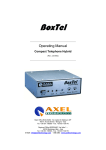
Download Compact Telephone Hybrid
Transcript
BoxTel
Compact Telephone Hybrid
Operating manual
(Rev. 1.5)
Sede BOLOGNA: Via Caduti Di Sabbiuno 6/F –
40011 Anzola Emilia - Bologna - Italy
Tel. +39 051 736555 - Fax. +39 051 736170
Sede BERGAMO: Via Italia 1 –
24030 Medolago (Bg) – Italy
e-mail: [email protected] - web site: www.axeltechnology.com
This manual is for use with the following product :
Boxtel
Axel Technology SRL
All Rights Reserved
Via Caduti Di Sabbiuno 6/F - 40011 Anzola Emilia - Bologna - Italy
Tel. +39 051 736555 – + 39 051 736154
Fax. +39 051 736170
e-mail: [email protected] - web site: www.axeltechnology.com
Information in this document is subject to change without notice and does not represent a commitment on the part of the
vendor. This manual images could differ a bit from the equipment actual design. Axel Technology SRL shall not be liable for
any loss or damage whatsoever arising from the use of information or any error contained in this manual.
No part of this manual may be reproduced or transmitted in any form or by any means, electronic or mechanical, including
photocopying, recording, information storage and retrieval systems, for any purpose other than the purchaser’s personal use,
without the express written permission of Axel Technology SRL.
Pag. 2
CONTENTS
1 CONTENTS
1
CONTENTS .............................................................................................................................................................. 3
2
INTRODUCTION .................................................................................................................................................... 4
3
SAFETY WARNINGS / ISTRUZIONI PER LA SICUREZZA .......................................................................... 5
3.1
FOREWORD...................................................................................................................................................... 5
4
SAFETY WARNINGS ............................................................................................................................................. 6
5
CONSIGNES DE SÉCURITÉ IMPORTANTES .................................................................................................. 7
6
ISTRUZIONI IMPORTANTI PER LA SICUREZZA ......................................................................................... 8
7
WICHTIGE SICHERHEITSHINWEISE.............................................................................................................. 9
8
INSTRUCCIONES IMPORTANTES DE SEGURIDAD ................................................................................... 10
9
EQUIPMENT DESCRIPTION............................................................................................................................. 11
9.1
9.2
10
10.1
10.2
10.3
10.4
10.5
FRONT PANEL ............................................................................................................................................... 11
REAR PANEL.................................................................................................................................................. 12
WIRING AND CONNECTIONS...................................................................................................................... 13
AUDIO INPUT (SEND)................................................................................................................................... 13
AUDIO OUTPUT (RECEIVE)......................................................................................................................... 14
THE REMOTE INTERFACE........................................................................................................................... 15
INTERFACES TO OXYGEN 5 AND OXYGEN 7 MIXING CONSOLES ..................................................... 16
TELEPHONE LINE CONNECTION............................................................................................................... 17
11
TECHNICAL SPECIFICATIONS ................................................................................................................... 18
12
WARRANTY ...................................................................................................................................................... 18
Pag. 3
INTRODUCTION
2 INTRODUCTION
BoxTel is a very small analog telephone hybrid, especially designed for all those applications (OB Van, news
gathering, out side links, etc) where weight and dimensions are crucial.
BoxTel features an high-tech ‘heart’, providing high level performance. BoxTel may be easily connected to
the most diffused audio consoles on the market thanks to its complete connecting features.
BoxTel is directly powered by telephone lines: no longer cares and warries about battery charge, cables and
availability of the Main AC voltage….
Main features:
- Balanced audio input (jack 6.3 mm) with level control
- Balanced audio output (jack 6.3 mm) with level control.
- 2 wire interface with parallel connection to an external telephone set
- Remote and direct control of line hooking and incoming call signalling functions
- Automatic line compensation
- Internal buzzer on/off
- Powered by telephone line
This appliance is connected to telephone networks indirectly through interface (in-house telephone
exchange). Direct connection to the public telephone net is under sole responsibility of the user.
Pag. 4
SAFETY WARNINGS / ISTRUZIONI PER LA SICUREZZA
3 SAFETY WARNINGS / ISTRUZIONI PER LA SICUREZZA
SAFETY WARNINGS
CONSIGNES DE SÉCURITÉ IMPORTANTES
ISTRUZIONI IMPORTANTI PER LA SICUREZZA
WICHTIGE SICHERHEITSHINWEISE
INSTRUCCIONES IMPORTANTES DE SEGURIDAD
(Rel. 1.1)
3.1
FOREWORD
For your own safety and to avoid invalidation of the warranty all text marked with these Warning
Symbols should be read carefully.
Information in this manual is subject to change without notice and does not represent a commitment on the
part of the vendor.
The manufacturer shall not be liable for any loss or damage whatsoever arising from the use of information
or any error contained in this manual, or through any mis-operation or fault in hardware contained in the
product.
It is recommended that all maintenance and service on the product should be carried out by the
manufacturer or its authorised agents. The manufacturer cannot accept any liability whatsoever for any loss
or damage caused by service, maintenance or repair by unauthorised personnel.
Pag. 5
SAFETY WARNINGS
4
SAFETY WARNINGS
The installation and servicing instructions in this manual are for use by qualified personnel only.
-
Read All Instructions. All safety and operating instructions must be read before operating the product. They also
must be retained for future reference, as it contains a number of useful hints for determining the best combination of
equipment settings for Yr particular application.
-
Heed All Warnings. All warnings on the product and those listed in the operating instructions must be adhered to.
-
Heat. This product must be situated away from any heat sources such as radiators or other products (including
power amplifiers or transmitters) that produce heat.
-
Lightning. For added protection for this product during a lightning storm, or when it is left unattended and unused for
long periods of time, unplug it from the telephone line. This will prevent damage to the product due to lightning and
line surges
-
Installation. Configuration and installation should only be carried out by a competent installation engineer
-
Cabling. Using high quality wires, well protected. Make sure the cable integrity.
This symbol alerts you to the presence of dangerous voltage inside the closure – voltage which
may be sufficient to constitute a risk of shock. Do not perform any servicing other than that
contained in the operating instructions. Refer all servicing to qualified personnel
The exclamation point within an equilateral triangle is intended to alert the user to the presence of
important operating and maintenance (servicing) instructions in the literature accompanying the
appliance.
THIS APPARATUS MUST BE EARTHED !
Pag. 6
CONSIGNES DE SÉCURITÉ IMPORTANTES
5
CONSIGNES DE SÉCURITÉ IMPORTANTES
-
Lire ces consignes
-
Conserver ces consignes
-
Observer tous les avertissements
-
Suivre toutes les consignes
-
Ne pas utiliser cet appareil à proximité de l’eau
-
Ne pas installer à proximité d'une source de chaleur telle qu'un radiateur, une bouche de chaleur, un poêle ou
d'autres appareils (dont les amplificateurs) produisant de la chaleur.
-
Débrancher l’appareil pendant les orages ou quand il ne sera pas utilisé pendant longtemps.
-
Confier toute réparation à du personnel qualifié. Des réparations sont nécessaires si l’appareil est endommagé
d’une façon quelconque, par exemple: liquide renversé ou objet tombé à l’intérieur de l’appareil, exposition de
l’appareil à la pluie ou à l’humidité, appareil qui ne marche pas normalement ou que l’on a fait tomber.
Ce symbole indique la présence d'une tension dangereuse dans l'appareil constituant un risque de
choc électrique.
Ce symbole indique que la documentation fournie avec l'appareil contient des instructions
d'utilisation et d'entretien importantes.
Pendant son usage, l’appareil doit etre branchee à la prise de terre
Pag. 7
ISTRUZIONI IMPORTANTI PER LA SICUREZZA
6 ISTRUZIONI IMPORTANTI PER LA SICUREZZA
-
Leggere le presenti istruzioni
-
Conservare queste istruzioni
-
Osservare tutte le avvertenze
-
Seguire scrupolosamente tutte le istruzioni
-
Non usare questo apparecchio in prossimità di acqua
-
Non installare l'apparecchio accanto a fonti di calore quali radiatori, aperture per l'afflusso di aria calda, forni o
altri apparecchi (amplificatori inclusi) che generino calore
-
Scollegare l’apparecchio dalla presa telefonica durante i temporali o quando inutilizzato a lungo
-
Per qualsiasi intervento, rivolgersi a personale di assistenza qualificato. È’ necessario intervenire sull’apparecchio
ogniqualvolta si verificano danneggiamenti di qualsiasi natura. Ad esempio, è entrato liquido nell’apparecchio o sono
caduti oggetti su di esso, l’apparecchio è stato esposto alla pioggia o all’umidità, non funziona normalmente o è
caduto.
-
Non esporre a sgocciolamenti o spruzzi.
Questo simbolo indica la presenza di alta tensione all'interno dell'apparecchio, che comporta rischi di
scossa elettrica.
Questo simbolo indica la presenza di istruzioni importanti per l'uso e la manutenzione nella
documentazione in dotazione all'apparecchio.
L’APPARATO DEVE ESSERE CONNESSO A TERRA.
Pag. 8
WICHTIGE SICHERHEITSHINWEISE
7 WICHTIGE SICHERHEITSHINWEISE
-
Diese Hinweise LESEN
-
Diese Hinweise AUFHEBEN
-
Alle Warnhinweise BEACHTEN
-
Alle Anweisungen BEFOLGEN
-
Dieses Gerät NICHT in der Nähe von Wasser verwenden
-
KEINE Lüftungsöffnungen verdecken. Gemäß den Anweisungen des Herstellers einbauen
-
Nicht in der Nähe von Wärmequellen, wie Heizkörpern, Raumheizungen, Herden oder anderen Geräten
(einschließlich Verstärkern) installieren, die Wärme erzeugen
-
Alle Reparatur- und Wartungsarbeiten von qualifiziertem Kundendienstpersonal DURCHFÜHREN LASSEN.
Kundendienst ist erforderlich, wenn das Gerät auf irgendwelche Weise beschädigt wurde, z.B. wenn Flüssigkeiten in
das Gerät verschüttet wurden oder Fremdkörper hineinfielen, wenn das Gerät Regen oder Feuchtigkeit ausgesetzt
war, nicht normal funktioniert oder fallen gelassen wurde.
-
Dieses Gerät vor Tropf- und Spritzwasser SCHÜTZEN.
Dieses Symbol zeigt an, dass gefährliche Spannungswerte, die ein Stromschlagrisiko darstellen,
innerhalb dieses Geräts auftreten.
Dieses Symbol zeigt an, dass das diesem Gerät beiliegende Handbuch wichtige Betriebs- und
Wartungsanweisungen enthält.
Das Gerät muss für den Betrieb geerdet werden.
Pag. 9
INSTRUCCIONES IMPORTANTES DE SEGURIDAD
8 INSTRUCCIONES IMPORTANTES DE SEGURIDAD
-
LEA estas instrucciones
-
CONSERVE estas instrucciones
-
PRESTE ATENCION a todas las advertencias.
-
SIGA todas las instrucciones
-
NO utilice este aparato cerca del agua
-
No instale el aparato cerca de fuentes de calor tales como radiadores, registros de calefacción, estufas u otros
aparatos (incluyendo amplificadores) que produzcan calor
-
DESENCHUFE el aparato durante las tormentas eléctricas, o si no va a ser utilizado por un lapso prolongado.
-
TODA reparación debe ser llevada a cabo por técnicos calificados. El aparato requiere reparación si ha sufrido
cualquier tipo de daño, si se derrama líquido sobre el aparato o si caen objetos en su interior, si ha sido expuesto a
la lluvia o la humedad, si no funciona de modo normal, o si se ha caído.
-
NO exponga este aparato a chorros o salpicaduras de líquidos. NO coloque objetos llenos con líquido, tales como
floreros, sobre el aparato .
Este símbolo indica que la unidad contiene niveles de voltaje peligrosos que representan un riesgo
de choques eléctricos.
Este símbolo indica que la literatura que acompaña a esta unidad contiene instrucciones importantes
de funcionamiento y mantenimiento.
Para reducir el riesgo de descargas, esta unidad debe ser conectada a tierra.
Pag. 10
EQUIPMENT DESCRIPTION
ENG
9 EQUIPMENT DESCRIPTION
9.1
FRONT PANEL
- Send control: it adjusts the level of audio sent to telephone caller through the ‘Send’ connector on the rear
panel.
- Receive control: It controls the level of the signal incoming from telephone caller.
The ‘received’ signal is provided on the Receive Jack connector (rear panel).
- HOOK button: it allows Line hooking. This switch hooks / hangs up the hybrid from the telephone line.
Hook LED switchs on accordingly.
- Call LED. It blinks when a call (ring) is coming in and lights firmly while line is hooked. Please note: LED
switchs on only if phone line is connected.
- On / Off micro-switcher: it enables / disables ring buzzer inside the hybrid.
Pag. 11
EQUIPMENT DESCRIPTION
9.2
ENG
REAR PANEL
- Receive Output (transformer balanced): it provides the audio signal incoming from telephone caller
- Send Input (transformer balanced): it receives audio signal from the source (mixing console) and sends it
to the telephone caller. Audio sent to caller must be a mix-minus (N-1). Mix-minus is a mix of all audio being
sent to the Send Jack of the hybrid, minus the incoming caller audio.
- Remote. 9 pin interface for remote line hooking and external call signalling
- LINE RJ11 socket for telephone line connection (LINE) – see relevant Paragraph
- PHONE RJ11 socket for connection of a standard telephone set (f.i. for dialling). Please note that ‘Phone’
socket is always active (i.e. it does not depend on the ‘Hook’ button state).
- Earth connection: in order to prevent damages due to lightnings surges or overvoltages on the telephone
line, connect BoxTel to earth.
BoxTel is automatically powered by telephone line. An external Voltage (+ 6V) is required only for
some applications (see parr. 10.3).
Pag. 12
WIRING AND CONNECTIONS
ENG
10 WIRING AND CONNECTIONS
We suggest to use high quality wires, well protected, and balanced connections to avoid external EMD.
10.1 AUDIO INPUT (SEND)
The equipment features a line input (transformer balanced) on female Jack connector.
Input impedance is set to 4 KOhm. Connector pinout is as following:
1
GND
TIP
RING
3
2
Gnd
Signal
Return
Example of balanced connection (XLR - Jack)
Example of unbalanced connection (PIN RCA - Jack), where cold pole (RING) is connected to the ground
(GND).
Pag. 13
WIRING AND CONNECTIONS
ENG
10.2 AUDIO OUTPUT (RECEIVE)
The equipment features outputs transformer balanced on Jack connector. Connector pinout is as following
1
GND
TIP
RING
3
2
Gnd
Signal
Return
Example of balanced connection (XLR - Jack)
Example of unbalanced connection (PIN RCA - Jack), where cold pole (RING) is connected to the ground
(GND).
Pag. 14
ENG
WIRING AND CONNECTIONS
10.3 THE REMOTE INTERFACE
BoxTel remote interface is based on a 9 pin SubD male interface and allows:
-
Remote hooking of telephone line
-
Incoming call signalling.
The interface has been especially designed for simple connction to Oxygen 5 and Oxygen 7 consoles.
INCOMING CALL SIGNALLING
A photocoupler inside BoxTel (pin 8 = collector and pin 1 = emitter - see ‘A’ in the picture below) provides a
low-resistance closure (150 Ohm) every time phone line rings. Max current allowed: 10 mA.
SubD – 9p
Male connector
6
1
9
5
Pin 1
Pin 2
Pin 3
Pin 4
Pin 5
Pin 6
Pin 7
Pin 8
Pin 9
GND
N.C.
N.C.
Base of transistor driving HOOK relay.
Internally shortcircuited to Pin 6 and 9
External supply (+ 6 V DC) input
N.C.
Ring photocoupler collector
Internally shortcircuited to Pin 6 and 5
An external LED (Ring LED in the picture here-above) must be connected to pins 9 and 8 through a 470
Ohm resistor (see R1). Pin 6 must be fed with + 6 V DC voltage.
SubD – 9p
Male connector
6
1
9
5
Pin 1
Pin 2
Pin 3
Pin 4
Pin 5
Pin 6
Pin 7
Pin 8
Pin 9
GND
N.C.
N.C.
Base of transistor driving HOOK relay.
Internally shortcircuited to Pin 6 and 9
External supply (+ 6 V DC) input
N.C.
Ring photocoupler collector
Internally shortcircuited to Pin 6 and 5
Internal Photocoupler (‘A’) can directly drive an external Lamp (like Mr. Light by Axel Technology). In this
case, pin 8 of BoxTel interface must be connected to the central pin of Mr. Light connector.
LINE HOOKING
Pins 5 and 4 allows remote line hooking command (provided through either a photocoupler or a clean
contact closure). An external powering is required for this aim. Please feed Pin 6 with + 6 V DC.
Pag. 15
WIRING AND CONNECTIONS
SubD – 9p
Male connector
6
1
9
5
Pin 1
Pin 2
Pin 3
Pin 4
Pin 5
Pin 6
Pin 7
Pin 8
Pin 9
ENG
GND
N.C.
N.C.
Base of transistor driving HOOK relay.
Internally shortcircuited to Pin 6 and 9
External supply (+ 6 V DC) input
N.C.
Ring photocoupler collector
Internally shortcircuited to Pin 6 and 5
10.4 INTERFACES TO OXYGEN 5 AND OXYGEN 7 MIXING CONSOLES
BoxTel remote interface has been designed for direct connection to Telco modules of OXYGEN 5 and
OXYGEN 7 mixing consoles by Axel Technology.
A regular, not crossed Pin – to – Pin 9 pole cable featuring standard RS232 connectors is required (9 pin
serial connection computer type).
1
2
3
4
5
6
7
8
9
1
2
3
4
5
6
7
8
9
9pM
9pF
Pag. 16
WIRING AND CONNECTIONS
ENG
10.5 TELEPHONE LINE CONNECTION
BoxTel hybrid operate on analog telephone lines.
MAKE SURE this appliance is connected to POTS / PSTN, analogue lines
DO NOT CONNECT this appliance to digital Telephone lines
DO NOT CONNECT this appliance to ADSL telephone lines, even if filtered.
In order to avoid any Hum and for EMC reasons, this unit must be earthed via earthing
screws on the rear panel.
This appliance is connected to telephone networks indirectly through interface (in-house
telephone exchange / PABX). Direct connection to the public telephone net is under sole
responsibility of the user.
RJ11 socket will accept 4 conductor modular plugs, but only the 2 central pins (number 2 and 3) are
typically used:
CONNECTOR PIN-OUT
Pin
Description
1
2
3
4
n.c.
Tel line
Tel line
n.c.
This unit allows the connection on parallel of a standard telephone set (for dialling services). Please note that
‘Phone’ socket is always active (i.e. it doesn’t depend on the ‘Hook’ button state) and it has the same PinOut as the LINE socket.
The telephone hybrid interface is powered by the same power flowing also into the
external telephone set. In the event You will experience some lack in the audio
performance or in the telephone hybrid operation (no Ring, no Hook, etc), try to
disconnect the Telephone Set itself.
Pag. 17
TECHNICAL SPECIFICATIONS
ENG
Should the device be put out of action due to being struck by lightning or excess voltage,
disconnect it from the telephone line without delay. Do not reconnect until the device
has been checked. If in doubt contact the technical support service.
Make sure there is suitable lightning protection to protect the device.
Alternatively you should disconnect all connectors from the device during a storm or
when the device is going to be unsupervised or not used for a longer period of time.
These measures will protect against damage by lightning or excess voltage.
11 TECHNICAL SPECIFICATIONS
AUDIO PROGRAM IN / OUT
Connectors
Input impedance
Output level *
Output impedance
Noise on Receive output
Send / Receive separation
Jack stereo 6.3 mm,.
4 KOhm (transformer bal)
-inf to + 7 dBm
2 KOhm (transformer bal)
less than - 80 dBm (DIN noise)
less than 20 dB**
GENERAL DATA
Power Supply
Dimension
Weight
Powered by telephone line
44 x 106 x 114mm
430 g
LINE INTERFACE
Connector
Nominal input level
Nominal output level
Compensation mode
Impedance
RJ11
- 6 dBm
- 6 dBm
electronic
600 Ohm
REMOTE INTERFACE
Ext signaling for incoming call
Remote line hooking
optocoupled
relay closure, ext. powered
* nominal line level : - 6 dBm
** it can vary depending on characteristics of telephone line
All measurements are intended at 1 kHz.
12 WARRANTY
The manufacturer offers a 1-year ex works warranty.
Do not open the equipment. The warranty shall be voided if any of the warranty seals are broken.
The manufacturer shall not be liable for damage of any kind deriving from or in relation to incorrect use of the
product.
Pag. 18


