1
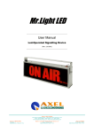
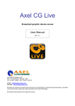
Streamer RX,
Streamer RTX
Audio networking system
User Guide
Rel 1.5 English (international)
Headquarter BOLOGNA: Via Caduti Di Sabbiuno 6/F
40011 Anzola Emilia - Bologna - Italy
Tel. +39 051 736555 - Fax. +39 051 736170
Regional BERGAMO: Via Italia 1
24030 Medolago (Bg) – Italy
Tel. +39 051 736555 - Fax. +39 051 736170
e-mail: [email protected] - web site: www.axeltechnology.com
2
This manual is for use with the following product :
Streamer RX and Streamer RTX
Axel Technology SRL
All Rights Reserved
Via Caduti Di Sabbiuno 6/F - 40011 Anzola Emilia - Bologna - Italy
Tel. +39 051 736555 – + 39 051 736154
Fax. +39 051 736170
e-mail: [email protected] - web site: www.axeltechnology.com
Information in this document is subject to change without notice and does not represent a commitment on the part of the
vendor. This manual images could differ a bit from the equipment actual design. Axel Technology SRL shall not be liable
for any loss or damage whatsoever arising from the use of information or any error contained in this manual.
No part of this manual may be reproduced or transmitted in any form or by any means, electronic or mechanical,
including photocopying, recording, information storage and retrieval systems, for any purpose other than the purchaser’s
personal use, without the express written permission of Axel Technology SRL.
3
TABLE OF CONTENTS
1
2
2
3
Streamer Control Software installation ................................................... 5
Installation of STREAMER RX .................................................................. 8
How To Decode Audio Streaming With “Streamer RX” .......................14
How To Encode Audio Streaming With “Streamer RTX” ....................17
4
ENG
1 Streamer Control Software installation
Inside the official Axel Technology Box is available the CD with lot of information, DOC and
firmware upgrade or reinstallaer. The software that must be installed to control the Streamer is
“Streamer Control”
1- Select Streamer Control.exe and press Return
2- Select the language and press NEXT
3- This is the Welcome screen (press NEXT)
5
ENG
4- Select the destination folder
5- Select the Programm destination folder
6
ENG
6- The software will install all the driver, dll and all the things necessary for the installation. A
reboot is necessary after the installation (and suggested)
7
ENG
“Streamer RTX” device
“Streamer RX” device
Model : Streamer
TX/RX
S-N : STR- XXxxXX
RX X
00-C0-E0-00-A0-00
MAC :
Model : Streamer
TX/RX X
S-N : STR- XXxxXX
RX
MAC :
00-C0-E0-00-A0-00
Warning! The installation procedure must be done with only ONE “Streamer” at the time
2 Installation of STREAMER RX
1. Plug the network cable into the network port of the “Streamer RX” device and the other end into
your hub or switch.
2. Plug the jack of your earphone into the headphone output.
3. Plug the power supply into the power jack of the device and the other end into the power outlet of
the wall.
4. After few seconds, will play a typical sound if a network is founded.
5. To verify the IP address assignement and manage the other parameters of “Streamer” you can use
Streamer Control software. Install and running Streamer Control. Verify that no firewall is active into
your PC.
8
ENG
6. Pushing Get List ! button, you will see as follows:
DHCP server status detector
“Streamer”
device
To configure the “Streamer” you have to pay attention to DHCP server status detector. If DHCP
ACTIVE is displayed you can procede from step 7. If the DHCP server status detector shows DHCP
NOT PRESENT procede from step 9.
7. By clicking on device inside the list box you will have all the parameters of the item selected.
Default parameters stored
Parameters assigned to “Streamer” by DHCP server
in “Streamer” memory
“Streamer” device
selected
GPIO settings
Decoder settings
Decoding test utility
Audio decoding settings
Encoder settings
9
ENG
8. The active parameters of the “Streamer” that you selected, will be showed into EEPROM and RAM
column. Now you can test the decoder audio function using UDP Streaming Test utility. By clicking
on the START button of UDP Streaming Test there will be the streaming of an audio MP3 file to the
IP address of “Streamer” selected. The suond will be played through the headphone and the RCA
pin (“Streamer” only, not “In-Streamer”). The audio parameters, like volume, bass, treble and
loudness can be changed via the Audio setting. The streaming will stop at the end automatically but
yuo can stop it in any moment by pressing the STOP button.
END OF INSTALLATION OF “STREAMER RX”
10
ENG
9. If DHCP NOT FOUND message will appear on the top of NS1 Tools form this means that any DHCP
server is present in your network and that any IP address has been assigned to “Streamer”.
Therefore, IP values of “Streamer” have to be assigned manually. We suggest to chose carefully
your IP address or to contact you network administrator to avoid any conflict with other network
devices.
10. To set manually the parameters of “Streamer” you have to select the device in the list box. After the
Warning messages you will be ready to assign the network values to “Streamer”.
“Streamer” device
selected
11
ENG
Default Parameters stored to Streamer memory
11. Set the network parameters starting from IP address to DNS address into the EEPROM column.
Click each Set button to store the relative value.
Parameters
memory
assigned
manually
in
“Streamer”
12
ENG
12. Press Get List ! button to refresh the display of “Streamer” selection.
13. Selecting the “Streamer” device will show you the new network parameters. As you will see the
EEPROM parameters will be transferred to RAM column. This means that your “Streamer” can be
reached on the network through the new IP value stored.
14. Now you can test the decoder audio function using UDP Streaming Test utility. By clicking on the
START button of UDP Streaming Test there will be the streaming of an audio MP3 file to the IP
address of “Streamer” selected. The suond will be played through the headphone and the RCA pin
(Streamer only, not In-Streamer). The audio parameters, like volume, bass, treble and loudness can
be changed via the Audio setting. The streaming will stop at the end automatically but yuo can stop
it in any moment by pressing the STOP button.
END OF INSTALLATION OF “STREAMER”
13
ENG
2 How To Decode Audio Streaming With “Streamer RX”
For installation and configuration refer to Chapter 1
1. To manage the decoding parameters of “Streamer” you can use Streamer Control. Verify that no
firewall is active into your PC.
2. Pushing Get List ! button, you will see as follows
“Streamer”
device
14
ENG
3. By clicking on device inside the list box all the parameters of the item selected will appear. Now you
can set the decoding parameters.
“Streamer RX”
decoding settings
“Streamer
RX” buffer
delay
Test tool
“Streamer RX” decoding audio
settings
4. Streamer RX can decode only UDP streamings. To decode an UDP audio streaming you have to
press the UDP button into “Streamer RX” decoding setting section. Then “ANNOUNCEMENT (UDP
mode)” message will be displayed in the right window. If a streaming is addressed to the multicast
or unicast IP address of “Streamer RX” this will decode it immediately. Depending on the network
traffic, it could be necessary to set the “Streamer RX” buffer delay (values admitted from 0 to 500
ms).
If you want to decode a TCP streaming you have to mount the memory option on the “Streamer
RX” board by upgrading it into Streamer RX version.
5. You can check the “Streamer RX” proper decoding by the UDP Streaming Test. By pressing the
START button a short mp3 file will be sent to the “Streamer RX” selected. You can also check the
right audio decoding of all the “Streamer RX” devices on the network simply by pressing Get List !
followed by START button: the same short mp3 file will be sent to the default “Streamer” IP
multicast address.
6. During playback you can set volume, bass and treble level and choose either to activate or not the
loudness of the “Streamer RX selected”. All the values will be stored in the “Streamer RX”
EEPROM. You can also reset to default values the audio parameters by pressing Reset button.
15
ENG
16
ENG
3 How To Encode Audio Streaming With “Streamer RTX”
For installation and configuration refer to Chapter 1
1. To manage the encoding parameters of “Streamer” you can use NS1 Tools software. Verify that no
firewall is active into your PC.
2. Pushing Get List ! button, you will see as follows
“Streamer
XX” device
17
ENG
3. By clicking on device inside the list box you will have all the parameters of the item selected. Now
you can set the encoding parameters.
“Streamer”
encoding
4. The parameters neededs to start to encoding are:
IP Address: unicast or multicast IP address of “Streamer” player/s targets
Port: destination port of “Streamer” player/s targets. All the “Streamer” models are ready to
receive the streaming throught 6244 port.
Frequency: audio sampling frequency.
Channels: mono or stereo mode. If you choose to use the microphone input remember to use
the 1 channel option.
Bit Reservoir: to improve the streaming audio quality it have to set on 0
Quality: The encoder uses Variable Bitrate Encoding (VBR) to realize optimal compression of
the audio data. The setting of a fixed bitrate is replaced with setting a quality level
that preserves audio quality in critical sections and enhances compression otherwise.
The minimum bitrate (in case of digital zero samples) is 32 kbit/s for MPEG 1 and 8
kbit/s for MPEG 2. The maximum bitrate is 192 kbit/s for MPEG 1 and 160 kbit/s for
MPEG 2. The following table gives an overview on the average encoding bitrate that
can be expected for common audio signals at different quality settings and sample
rates.
18
ENG
Average bitrate in kbit/s for fs/kHz
Quality
settings
44.1
stereo
22.05
stereo
44.1
mono
22.05
mono
0
75
39
65
35
1
80
41
68
38
2
90
45
63
40
3
100
50
80
45
4
120
60
90
50
5
140
80
105
60
6
160
110
125
75
7
170
130
140
90
Line: Line input selector. The line input signal can be connected to the PIN jacks
(unbalanced)
Mic: Microphone input selector.
Dig: Digital SPDIF audio input. The digital input and output are available only for the
“Streamer” equipedd with the optional service board
Monitor: Monitor level of the audio input after the compression process. The monitor out is
available from the 3,5 mm jack.
Mic input gain: Microphone level input gain.
Left & Right Line level input gain.
input gain:
SET: This button sets the encoding parameters into the “Streamer” and start automatically
the encoding session.
19
ENG
«OBB - IBB» Option for Streamer RX and
Streamer RTX
Audio Balanced INPUT
............
COLD
-
Streamer RTX
HOT
+
GND
COLD
-
LEFT Ch
HOT
+
GND
RIGHT Ch
Audio Balanced OUTPUT
............
COLD
-
Streamer RX
HOT
+
GND
COLD
-
LEFT Ch
HOT
+
GND
RIGHT Ch
«GP» Option for Streamer RX and
Streamer RTX GP INPUT
GPI 7
Streamer RTX
GPI 6
............
GND
IN
GND
GND
IN
GND
GP OUTPUT
GPO 7
Streamer RX
GPO 6
............
NC
C
NO
NC
C
NO
20
ENG
DETAILS for «IBB - OBB» Option for Streamer RX and
Streamer RTX
Audio Balanced INPUT
LEFT Ch
COLD
-
HOT
+
GND
RIGHT Ch
COLD
-
HOT
+
GND
............
Streamer RTX
RIGHT Ch
LEFT Ch
COLD
HOT
+
GND
BLACK
RED
SHIELD
SHIELD
3
2
1
Audio Balanced OUTPUT
LEFT Ch
COLD
-
HOT
+
GND
RIGHT Ch
COLD
-
HOT
+
GND
............
Streamer RTX
RIGHT Ch
LEFT Ch
COLD
HOT
+
GND
BLACK
RED
3
2
1
21
ENG
Balanced Connection (IBB-OBB option)
Streamer and InStreamer mount onboard (optional by request) an electronically balanced input
and output connector board (IOB Option)
The standard configuration allows three connectors as standard EIA RS-297-A recommendations.
Pin
Function
1
Chassis ground (cable shield)
2
positive polarity terminal ("hot")
3
return terminal[2] ("cold")
The maximum input signal is 0.775 Vpp (0 dBu)
The maximum output signal is 3.781 Vpp (6 dBu)
22
ENG
General Purpose Input Output (GP Option)
The Streamer and InStreamer equipment allows 2 General Purpose (GP) Input and Output. The
GP name are GPI6 and GPI7 for the inputs and GPO6 and GPO7 for the output
GPInput
In order to activate GP6 and GP7 inside Streamer, place directly on ground the “In” signal ( IN to
GND) as shown in picture.
It is already possible employs both connectrs GND. Please remember that IN and GND are directly
connected to µProcessor (µP) equipment.
Pay attention to don’t connect external voltage to this connectors.
These connectors can be directly applied to Axel Technology equipments as BOBCAT and
BoxRelè, already made in order to manage all kind of signals coming from CD player, MD Player,
tape recorder, ISDN tunneling or Automation System.
GPOut
Inside InStreamer are presents two BiStable Relay, iIn order to employ the GPOut.
These Relays allows TWO condition: NC and NO.
NC = Normally Close
NO = Normally Open
C = Common Contact
Details:
When there are no activation in GPI the Relay contact stay on NC. When GPI become activated,
the output relay change the contact closure versus NO, as showed in picture.
In the example figure, a cc generator is connected in the common contact and the same point
directly to LAMP1 and LAMP2.
In GPI non-activation position, LAMP1 is ON, and LAMP2 is OFF
In GPI Activation position, LAMP1 is OFF, and LAMP2 is ON
Working votage = 5 Vcc
Maximum Voltage (breakdown) = 100 Vcc
23
ENG
DETAILS for «GP» Option for Streamer and InStreamer
GP INPUT
GPI 7
GND
IN
GPI 6
GND
IN
GND
GND
............
.
.
.
.
.
.
Streamer
To Activate GPI 6 and GPI 7 close IN
versus GND as showed below
When GPO 6 and/or GPI 7 are Activated
Relay6 and Relay7 change from NC to NO
.
.
InStreamer
............
NC
C
NO
GPO 7
NC
C
NO
GPO 6
+
-
GP OUTPUT
LAMP1 LAMP2
EXAMPLE
Nominal Value:
Vn= 12V
In= 500mA
Maximum Value
(breakdown)
Vm= 100V
Im= 1A
24
ENG
6 Warranty
The manufacturer offers a 1-year ex works warranty.
Do not open the equipment. The warranty shall be voided if any of the warranty seals are broken.
The manufacturer shall not be liable for damage of any kind deriving from or in relation to incorrect use of the
product.
25