1
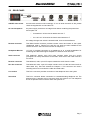
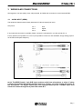
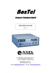
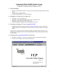
Macrotel DIGITAL
DIGITAL STUDIO TELEPHONE HYBRID
Operating manual
(Rel. 1.1)
Via Caduti Di Sabbiuno 6/F • 40011 Anzola Emilia • Bologna • Italy +39 051 736555 • Fax. +39 051 736170
e-mail: [email protected] • web site: www.axeltechnology.com
Macrotel DIGITAL
Pag. 2
Macrotel DIGITAL
CONTENTS
1
INTRODUCTION .................................................................................................................................................... 4
1.1
2
EQUIPMENT DESCRIPTION ............................................................................................................................... 5
2.1
2.2
3
AUDIO INPUT (SEND) ..................................................................................................................................... 7
AUDIO OUTPUT (RECEIVE AND REC OUT)..................................................................................................... 8
REMOTE INTERFACE ..................................................................................................................................... 9
TEL LINE CONNECTION ................................................................................................................................ 9
PHONE SET CONNECTION .......................................................................................................................... 10
HEADPHONES JACK ..................................................................................................................................... 10
SETTINGS .............................................................................................................................................................. 11
4.1
5
FRONT PANEL.................................................................................................................................................. 5
REAR PANEL .................................................................................................................................................... 6
WIRING AND CONNECTIONS ............................................................................................................................ 7
3.1
3.2
3.3
3.4
3.5
3.6
4
MAIN FEATURES............................................................................................................................................. 4
DIP SWITCHES SETTING.............................................................................................................................. 11
OPERATION .......................................................................................................................................................... 13
5.1
5.2
TRAINING THE TELEPHONE ECHO CANCELLER ................................................................................... 13
TRAINING THE MIX-MINUS........................................................................................................................ 13
6
BLOCK DIAGRAM............................................................................................................................................... 14
7
TECHNICAL SPECIFICATIONS ....................................................................................................................... 15
8
WARRANTY .......................................................................................................................................................... 15
Pag. 3
Macrotel DIGITAL
1 INTRODUCTION
Macrotel Digital is a single line digital telephone hybrid, especially designed to fit all TV and radio station
requirements.
With the variety of telephone systems in the world today, from cellular mobile phones to analog and to digital,
it’s increasingly difficult to have all callers sound the same on-air in a broadcast environment.
The Macrotel Digital uses digital signal processing (DSP) technology to continually adapt to telephone-line
conditions and to deliver the maximum isolation between the send and receive audio (> 55 dB).
With no echo and no "bottom of the barrel" sound, the Macrotel Digital is thus ideal when the very best audio
quality and uniformity is required for talk shows, news feeds, production, recording studios, and even internet
applications.
Several functions (selectable from front panel DIP switches) greatly expand its operation. Automatic
gain control (AGC) allows each call to be delivered at the same level. Built-in caller Ducking stage
reduces the caller's audio level when the announcer speaks. Auto mix-minus feature allows easy
installation to consoles with no mix-minus capability.
Additionally, the hybrid can automatically answer the telephone line after the first ring and automatically
disconnect it after the caller hangs up. The REC Output can be configured to contain a mix of send and
caller audio or caller audio only.
In accordance to mainland Europe, USA, Canada, and UK compliance standards, the Macrotel Digital is
perfect for your telephone application.
1.1
MAIN FEATURES
• Crystal clear, consistent audio quality
• Continual adaptation to POTS line conditions
• Best isolation between Send and Receive audio
• Selectable caller control (ducking)
• Worldwide compliant
• Full Remote control
• Selectable mic / line level input
• Selectable automatic mix-minus
• Selectable AGC on Receive signal
• Selectable auto-answer / auto-disconnect
Pag. 4
Macrotel DIGITAL
2 EQUIPMENT DESCRIPTION
2.1
FRONT PANEL
Send potentiometer
it adjusts the level of audio signal sent to phone caller. At its midpoint (6 o’clock
position), the pot is set for nominal send level (0dBm).
Aux-in potentiometer
It adjusts the level of the auxiliary send audio coming from the remote connector
input and going onto the telephone line to the caller. At its midpoint (6 o’clock
position), the pot is set for nominal level (0dBm).
Receive potentiometer it adjusts the phone subscriber audio level which is provided to the user ’s
equipment
Rec-Out potentiometer it adjusts the level of the audio at the Rec-Out connector. At its midpoint (6 o’clock
position), the pot is set for nominal level (0dBm).
DIP Switches
these DIP switches configure the hybrid’s system. Individual switch functions are
defined in Calibration Chapter
Send LED
it indicates the relative level of the send audio into the digital hybrid. Green
indicates nominal level, amber indicates caution, red indicates clipping.
Receive LED
it indicates the relative level of the caller audio from the telephone line. Green
represents nominal level, amber indicates caution, red indicates clipping.
Hook button
it allows Line hooking i.e. it connects the hybrid to the telephone line
Hook LED
it blinks when a call (ring) is coming in and lights firmly while line is hooked.
Please note: led switchs on only if phone line is connected
Off button
it disconnects the hybrid from the telephone line and mutes all audio going to and
from the telephone line
Off LED
it indicates the hybrid is not connected to an active phone line. The LED
illuminates red when the hybrid is powered
Volume Up / Down
these buttons control the audio level on the headphone monitor output. Pressing
once changes the level by 1dB. Pressing and holding a button sweeps the level up
or down
Pag. 5
Macrotel DIGITAL
2.2
REAR PANEL
ON/OFF main switch
the led inside switchs on/off accordingly. If it is off while the switch is ON, please
check the supplied AC cord and the fuse
AC cord receptacle
the power supply socket has an integral fuse drawer containing the power fuse
and a spare one
-
for 220/230 V AC the fuse is rated at 250 mA T
-
for 110/115 V AC tension the fuse is rated at 500 mA T
the voltage change-over switch is located inside, close to the transformer
Remote connector
This DB25 female connector provides remote control and status of the hybrid.
Unbalanced send in, Receive out ,and Rec out audio are also available at the
remote connector. See Connector Pinouts at Chapter 3.3
Headphone Monitor
1/4" jack. It provides connection to a headphone or to a small loudspeaker for
monitoring the caller audio signal. Capable of 1 watt into an 8 ohm load
Send connector
This balanced, female 3-pin XLR input receives audio from the source
(microphone or mixer) and sends it to the caller. Audio sent to the caller must be a
mix-minus.
Receive connector
This balanced, male, 3-pin XLR output contains the audio from the caller
Rec Out connector
This balanced, male, 3-pin XLR output contains a mix of caller and send audio or
caller audio only. See DIP switches at Chapter 4. This connector can feed a
recording device to record both the caller and send audio
Line socket
This RJ11 connector provides connection of the telephone line to the hybrid
Set socket
This RJ11 connector allows connection to a standard analog telephone set. The
telephone line is present at this connector when the hybrid is off. The telephone
line is not present at this connector when the hybrid is on
Pag. 6
Macrotel DIGITAL
3 WIRING AND CONNECTIONS
We suggest to use high quality wires, well protected, and balanced connections to avoid external EMD.
3.1
AUDIO INPUT (SEND)
The equipment features electronically balanced XLR female inputs (line level).
XLR pinout:
Pin 1
Pin 2
Pin 3
Gnd
Signal
Return
If any balanced connection is possible, please connect the cold pole (Pin 3) to the ground (Pin 1).
Factory preset input impedance is 10 kΩ. Input impedance of 600 Ω is also available, simply setting jumpers
on the main board (see Chapter 4).
NOTE: The SEND female, 3-pin XLR input receives audio from microphone or mixer. If using
a single microphone that needs phantom power to operate, you must supply this power to
the microphone. The digital hybrid does not supply phantom power. Line/Mic input level
selection is done through front panel DIP switch # 4.
Pag. 7
Macrotel DIGITAL
3.2
AUDIO OUTPUT (RECEIVE AND REC OUT)
The equipment features XLR analog outputs electronically balanced by high-quality buffers, capable of
withstanding even low-impedance loads (600Ω), with levels of up to +20 dBu.
XLR pinout:
Pin 1
Pin 2
Pin 3
Gnd
Signal
Return
In case of unbalanced connections, connect the cold pole (Pin 3) to the ground (Pin 1).
Pag. 8
Macrotel DIGITAL
3.3
REMOTE INTERFACE
Remote Connector Pinout
Pin Description
1
2
3
4
5
6
7
8
9
10
11
12
13
14
15
16
17
18
19
20
21
22
23
24
25
Remote Hybrid On
Remote Hybrid Off
Not used
Not used
Switch / Indicator Common
Not used
Not used
+ 5 Volt dc (supplied via an internal 100 Ohm protection resistor)
Unbalanced AUX –IN Audio Input (0dBu nominal)
Unbalanced Receive Audio Output (0dBu nominal)
Unbalanced Rec Audio Output (0dBu nominal)
Monitor Mute Control*
Audio Common
Hybrid On Indication
Hybrid Off Indication
Not used
Not used
Switch/Indicator Common
Hybrid Send Presence Indicator
Hybrid Receive Presence Indicator
Switch/Indicator Common
Audio Common
Audio Common
Audio Common
Switch/Indicator Common
* Remote control provided via contact closure to Switch/Indicator
Common
** Remote indicators provided via open collector outputs to Indicator
Common (<15V, <39mA)
3.4
TEL LINE CONNECTION
Macrotel Digital hybrid operates on standard POTS (Plain Old Telephone Service) / PSTN (Public Switched
Telephone Network) analog telephone lines or an analog extension from a PBX via a standard RJ11
modular jack.
The RJ11 socket will accept 6 conductor modular plugs, but only the 2 central conductors (typically Red &
Green ) are used.
Pag. 9
Macrotel DIGITAL
3.5
PHONE SET CONNECTION
This RJ11 connector will accept 6 conductor modular plugs, but only the 2 central conductors (typically Red
& Green ) are used for connection to a standard analog telephone set. The telephone line is present at this
connector when the hybrid is off. The telephone line is not present at this connector when the hybrid is on
3.6
HEADPHONES JACK
1/4. Stereo Jack - Headphone plug allows connection to an external headphone
set.
Tip = + phase,
Ring = ground,
Sleeve = ground
1W output into an 8 Ohm load
Pag. 10
Macrotel DIGITAL
4 SETTINGS
4.1
DIP SWITCHES SETTING
DIP SWITCHES are .off. in the down position and .on. in the up position.
DIP SWITCH 1
Enables/disables the Burst Adapt feature. In the .off position (down) the hybrid is
in Auto Adapt Mode. In the .on. position (up) the hybrid will send a noise burst to
the telephone line and aggressively adapt before returning to Auto Adapt Mode.
Each press of the ON button will generate a new noise burst.
In either mode, the hybrid continually monitors and adapts to the changing
telephone line conditions in order to digitally cancel the telephone line echo and
provide the best send-to-caller separation possible
DIP SWITCH 2
Enables/disables the Caller Boost feature. In the .off. position (down) the caller
boost feature is disabled. In the .on. position (up) the hybrid adds 6dB of level
boost to the caller.s audio at the Receive connector.
DIP SWITCH 3
Allows the hybrid to work with two types of switches for external (remote) control
momentary and latching. In the .off. position (down) the ON/OFF control inputs
respond to momentary closures to ground.
This turns the hybrid on when it receives a momentary closure on the ON control
input and off when it receives a closure on the OFF control input.
In the .on. position (up) the OFF control input is disabled and the ON control input
responds to a latching closure to ground. This will cause the hybrid to turn on
when the latching switch is closed to ground and the hybrid will remain on until the
closure to ground is opened.
This DIP SWITCH setting also affects the operation of the front panel ON/OFF
buttons. See .previous Chapter for REMOTE CONTROL connector pinouts.
DIP SWITCH 4
Sets the gain of the SEND connector. In the .off. position (down) the input is a
nominal line level (0dBu) input. In the .on. position (up) the input is a mic level
providing +55dBu of input gain
DIP SWITCHES 5 & 6
Enables/disables the Caller Control (ducking) feature.
In the .on. position (up) the hybrid will provide caller control, which is the
suppression of caller audio when send audio is present.
In the .off. position (down) caller control is disabled. DIP SWITCH 5, when active,
adds 6dB of caller control and DIP SWITCH 6, when active, adds 12dB of caller
control. If both are active, then the sum of the two DIP SWITCHES is used, and
18dB of caller control is provided
DIP SWITCH 7
Enables/disables the Auto Answer feature. In the .off. position (down) the hybrid
will not automatically answer the telephone line. In the .on. position (up) the hybrid
will automatically answer the telephone line after the first ring
DIP SWITCH 8
Enables/disables the Auto Disconnect feature. In the .off. position (down) the
hybrid will not automatically disconnect the telephone line. In the .on. position (up)
the hybrid will automatically disconnect the telephone line after the caller hangs
up. Note: The telephone line must provide loop drop, loop reversal or call
progress signals in order for the Auto Disconnect feature to function. Most
telephone systems will provide loop drop shortly after the calling party hangs up.
Some PBX systems, but not all, will provide either loop drop or call progress tones
such as reorder tones or busy signals. The hybrid will detect most of these signals
and then auto disconnect the telephone line
DIP SWITCH 9
Enables/disables the Automatic Gain Control (AGC) feature. In the .off. position
(down) the AGC feature is disabled. In the .on. position (up) the AGC feature is
enabled. When enabled, the AGC feature normalizes the gain of the caller audio,
Pag. 11
Macrotel DIGITAL
augmenting the level of .soft. callers and attenuating the level of .loud. callers.
This helps provide more uniform caller audio levels at the caller output of the
hybrid. The AGC works to achieve an equivalent average caller level of -30dBm
from the telephone circuit
DIP SWITCH 10
Enables/disables the Automatic Mix-Minus feature. In the .off. position (down) the
Automatic Mix-Minus feature is disabled. In the .on. position (up) the Automatic
Mix-Minus feature is enabled. When Automatic Mix-Minus is enabled, it is not
necessary for you to create a mix-minus output with your console/mixer. You can
simply feed program audio to the send input of the hybrid, and the hybrid will
automatically remove the caller audio from the program mix and prevent it from
returning to the caller as echo, which prevents possible feedback. Note: This
option should only be enabled when no mix-minus facilities are available through
the console or mixer
DIP SWITCH 11
Not used
DIP SWITCH 12
Enables/disables the Aux Mix feature. In the .off. (down) position, the Rec OUT
and REMOTE Rec OUT will contain caller audio only. In the .on. (up) position the
Rec OUT and REMOTE Rec OUT audio will contain a mix of send and caller
audio
Pag. 12
Macrotel DIGITAL
5 OPERATION
5.1
TRAINING THE TELEPHONE ECHO CANCELLER
Upon connection to the telephone line, the digital hybrid will automatically begin its telephone echo
cancellation process. This will optimize the send to caller separation. If the send to caller separation is not
sufficient, you may force the hybrid to .train. itself to the telephone line by pressing and holding the ON
button for one second. After one second, the hybrid will emit a burst of white noise. The noise burst allows
the hybrid to aggressively adapt to the echo returning from the telephone network and allows the hybrid to
maximize its send-to-caller separation.
This noise burst can be generated at any time by pressing and holding the ON button for one second. To
force a noise burst on every connection to the telephone line, activate the BURST ADAPT DIP SWITCH 1.
See .DIP Switches setting at the previous Chapter.
5.2
TRAINING THE MIX-MINUS
Upon connection to the telephone line, the digital hybrid will automatically begin its mix-minus echo
cancellation processes. To verify/fine tune the calibration of the mix-minus, watch the SEND LED as the
caller speaks. If the SEND LED is not lighting or only flashing green on the caller.s audio peaks, then the
calibration is already complete. If the SEND LED is lighting solid green on caller audio, decrease the loop
gain via the SEND INPUT pot or the console level control and train the telephone echo canceller. As the
caller continues to speak, you should notice that the SEND LED will begin to illuminate less and less until it
no longer lights green on caller audio. This process may need to be repeated if the desired results are not
achieved or if the caller is complaining of excessive echo.
Pag. 13
Macrotel DIGITAL
6 BLOCK DIAGRAM
Pag. 14
Macrotel DIGITAL
7 TECHNICAL SPECIFICATIONS
GENERAL DATA
Power Supply
Dimension
Weight
Operating Temperature
Compliance
TELCO INTERFACE
220 / 110V 50 / 60 Hz 30VA
434x351x44mm (1 rack unit)
around 4 Kg
0-38°C
FCC, CSA, CE and CTR21
AUDIO IN / OUT
Tel line connector
Capability
Tel Set connector
RJ 11 (A-Lead supervision)
POTS line, analog extension from
a PBX or dry line (no DC offset
voltage).
RJ 11 (A-Lead supervision)
TELEPHONE TRANSMIT
Send input connector
Send input level
XLR, electr. balanced
Mic / Line sel. (-55 / 0 dBu)
Frequency Response
Signal to noise ratio
250Hz to 3.5kHz, ±1dB
>56dB
Send Input impedance
20 KΩ
Distortion
<0.2%
Receive Output connector
Receive Output nominal level
Receive Output impedance
REC Out connector
REC Out level
MONITOR Output Connector
MONITOR Output power
Send-to-Receive separation
Send to Receive Tail time
Mix-Minus Rec.to Send separ.
XLR, electr. balanced
0 dBu (adjustable)
50 Ω
XLR, electr. balanced
0 dBu (adjustable)
Jack ¼”
1W into 8 Ω load
> 55dB (250 Hz to 3.5 kHz)
32 milliseconds
50dB nominal
Level
Nominal Send input of 0dBu is
referenced to -15dBu across the
telephone line
Mix-Minus Tail time
32 milliseconds
REMOTE INTERFACE
Connector
Control Inputs
Status Outputs
Status Outputs type
Additional Audio I/O (unbal.)
TELEPHONE RECEIVE
Frequency Response
Signal to noise ratio
Distortion
250Hz to 3.5kHz, ±1dB
>56dB
<0.2%
Level
Nominal telephone line level of –
15dBu referenced to Receive
output of 0dBu
FRONT PANEL CONTROLS
DB 25 female
On, Off, and Monitor Mute
On, Off, Send Audio presence,
Receive Audio presence
open coll. (< 15V, < 39 mA)
Receive, REC, Aux-IN
On/Off
Send, Rcv, Rec, Aux-in Level
Monitor Volume Up / Down
Receive Boost Select
Remote Mom/Latching Select
Burst Adapt Select
Auto Answer/Disconn Select
Ducking Sel. (0, 6, 12, 18dB)
AGC Select
Auto Mix-Minus Select
Mic / Line Select
REC Send / Rcv mix Select
Specifications, pictures and graphic layout of this leaflet are furnished for informational use only and are
subject to change at any time without notice.
8 WARRANTY
The manufacturer offers a 1-year ex works warranty.
Do not open the equipment. The warranty shall be voided if any of the warranty seals are broken.
The manufacturer shall not be liable for damage of any kind deriving from or in relation to incorrect use of the
product.
Pag. 15