1
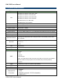
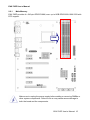
EAX-785E
AMD Turion /Athlon II Neo Processor
User’s Manual
1st Ed – March 11th 2011
EAX-785E User’s Manual
FCC Statement
THIS DEVICE COMPLIES WITH PART 15 FCC RULES. OPERATION IS
SUBJECT TO THE FOLLOWING TWO CONDITIONS:
(1) THIS DEVICE MAY NOT CAUSE HARMFUL INTERFERENCE.
(2) THIS DEVICE MUST ACCEPT ANY INTERFERENCE RECEIVED INCLUDING
INTERFERENCE THAT MAY CAUSE UNDESIRED OPERATION.
THIS EQUIPMENT HAS BEEN TESTED AND FOUND TO COMPLY WITH THE LIMITS
FOR A CLASS "A" DIGITAL DEVICE, PURSUANT TO PART 15 OF THE FCC RULES.
THESE LIMITS ARE DESIGNED TO PROVIDE REASONABLE PROTECTION AGAINST
HARMFUL INTERFERENCE WHEN THE EQUIPMENT IS OPERATED IN A
COMMERCIAL ENVIRONMENT. THIS EQUIPMENT GENERATES, USES, AND CAN
RADIATE RADIO FREQUENCY ENERGY AND, IF NOT INSTALLED AND USED IN
ACCORDANCE WITH THE INSTRUCTION MANUAL, MAY CAUSE HARMFUL
INTERFERENCE TO RADIO COMMUNICATIONS.
OPERATION OF THIS EQUIPMENT IN A RESIDENTIAL AREA IS LIKELY TO CAUSE
HARMFUL INTERFERENCE IN WHICH CASE THE USER WILL BE REQUIRED TO
CORRECT THE INTERFERENCE AT HIS OWN EXPENSE.
Copyright Notice
Copyright © 2011 Avalue Technology Inc., ALL RIGHTS RESERVED.
No part of this document may be reproduced, copied, translated, or transmitted in any form
or by any means, electronic or mechanical, for any purpose, without the prior written
permission of the original manufacturer.
A Message to the Customer
Avalue Customer Services
Each and every Avalue’s product is built to the most exacting specifications to ensure
reliable performance in the harsh and demanding conditions typical of industrial
environments. Whether your new Avalue device is destined for the laboratory or the factory
floor, you can be assured that your product will provide the reliability and ease of operation
for which the name Avalue has come to be known.
Your satisfaction is our primary concern. Here is a guide to Avalue’s customer services. To
ensure you get the full benefit of our services, please follow the instructions below carefully.
Technical Support
We want you to get the maximum performance from your products. So if you run into
technical difficulties, we are here to help. For the most frequently asked questions, you can
easily find answers in your product documentation. These answers are normally a lot more
2 EAX-785E User’s Manual
EAX-785E User’s Manual
detailed than the ones we can give over the phone. So please consult the user’s manual
first.
To receive the latest version of the user’s manual; please visit our Web site at:
http://www.avalue.com.tw/
If you still cannot find the answer, gather all the information or questions that apply to your
problem, and with the product close at hand, call your dealer. Our dealers are well trained
and ready to give you the support you need to get the most from your Avalue’s products. In
fact, most problems reported are minor and are able to be easily solved over the phone.
In addition, free technical support is available from Avalue’s engineers every business day.
We are always ready to give advice on application requirements or specific information on
the installation and operation of any of our products. Please do not hesitate to call or e-mail
us.
Headquarters and Branch
Avalue Technology Inc.
Avalue USA
Avalue Technology Inc.
7F, 228, Lian-cheng Road, Chung Ho City, Taipei,
200 Tornillo Way, Suite 210, Tinton Falls,
Taiwan
NJ 07712
Tel:+886-2-8226-2345
Tel: +1-732-578-0200
Fax: +886-2-8226-2777
Fax: +1-732-578-0250
Information:[email protected]
Information: [email protected]
Service: [email protected]
Service: [email protected]
BCM Advanced Research
BCM Advanced Research
an Avalue Company
Avalue Europe
7 Marconi, Irvine, CA92618
Aalsgaarde, Denmark
Tel: +1-949-470-1888
Tel: +45-7025-0310
Fax: +1-949-470-0971
Fax:+45-4975-5026
Information: [email protected]
Information: [email protected]
Web: www.bcmcom.com
Service: [email protected]
Avalue China
Avalue Japan
Avalue Technology Inc.
Avalue Technology Inc.
Room 805, Building 9,No.99 Tianzhou Rd.,
Caohejing Development Area,
Xuhui District, Shanghai
Avalue Europe A/S
Moelledalen 22C, 3140
2F keduka-Bldg, 2-27-3 Taito,
Taito-Ku, Tokyo 110-0016 Japan
Tel: +86-21-5169-3609
Tel: +81-3-5807-2321
Fax:+86-21-5445-3266
Fax: +81-3-5807-2322
Information: [email protected]
Service: [email protected]
Information: [email protected]
Service: [email protected]
EAX-785E User’s Manual 3
EAX-785E User’s Manual
Content
1.
Getting Started............................................................................................................5
1.1
Safety Precautions .........................................................................................5
1.2
Packing List ....................................................................................................5
1.3
Document Amendment History.......................................................................6
1.4
Manual Objectives..........................................................................................7
1.5
System Specifications ....................................................................................8
1.6
Architecture Overview – Block Diagram .......................................................11
2.
Hardware Configuration...........................................................................................12
2.1
Product Overview .........................................................................................13
2.2
Installation Procedure...................................................................................14
2.2.1
Main Memory ........................................................................................15
2.3
Jumper and Connector List ..........................................................................17
2.4
Setting Jumpers & Connectors.....................................................................19
2.4.1
Clear CMOS (CLRTC1).........................................................................19
2.4.2
Amplifier Controller (CN21) ...................................................................19
2.4.3
Power selector Ring/+5V/+12V (JCOMPWR1) .....................................20
2.4.4
Power selector Ring/+5V/+12V (JCOMPWR2/3/4) ...............................20
2.4.5
ATX power connector (ATXPWR1) .......................................................21
2.4.6
AT Power connector (ATX12V1) ...........................................................21
2.4.7
Azalia Front audio connector (AAFP1) ..................................................22
2.4.8
Chassis Fan connector (CHA_FAN1)....................................................22
2.4.9
CPU Fan connector (CPU_FAN1).........................................................23
2.4.10 Serial port 2/ 3/ 4 connector (COM 2/3/4)..............................................23
2.4.11 System Panel connector (F_PANEL1) ..................................................24
2.4.12 Amplifier connector (JAMP1).................................................................24
2.4.13 LCD Inverter connector (JBKL1) ...........................................................25
2.3.13.1 Signal Description – LCD Inverter Connector (JBKL1)) ......................25
2.4.14 General Purpose I/O connector (JDIO1) ...............................................26
2.4.15 LVDS connector (JLVDS1)....................................................................27
2.4.16 Cross fire Power connector (XFIRE_PWR1).........................................28
2.4.17 SPI programming connector (SPI1) ......................................................28
2.4.18 USB connector 56 & 78 (USB56/78) .....................................................29
3. Mechanical Drawing ....................................................................................................30
4 EAX-785E User’s Manual
EAX-785E User’s Manual
1. Getting Started
1.1 Safety Precautions
Warning!
Always completely disconnect the power cord from your
chassis whenever you work with the hardware. Do not
make connections while the power is on. Sensitive
electronic components can be damaged by sudden power
surge. Only experienced electronics personnel should open
the PC chassis.
Caution!
Always ground yourself to remove any static charge before
touching the CPU card. Modern electronic devices are very
sensitive to static electric charges. As a safety precaution,
use a grounding wrist strap at all times. Place all electronic
components in a static-dissipative surface or static-shielded
bag when they are not in the chassis.
Always note that improper disassembling could damage to the
motherboard. We suggest not to, in any circumstance remove the heatsink
without the correct instructions. If you really have to do it, please contact us
for further support.
1.2 Packing List
Before you begin installing your single board, please make sure that the
following items have been shipped:
z
z
z
z
z
z
1 x EAX-785E ATX Main Board
2 x SATA cable kit(SATA/power)
1 x COM 9P Cable W/O Bracket PH:2.00mm
1 x DRIVER CD (CD-R) without printed LOGO
1 x AMI BIOS label
1 x I/O Shield
EAX-785E User’s Manual 5
EAX-785E User’s Manual
1.3 Document Amendment History
Revision
st
1
Date
March 2011
6 EAX-785E User’s Manual
Comment
Initial Release
EAX-785E User’s Manual
1.4 Manual Objectives
This manual describes in detail the Avalue Technology EAX-785E Motherboard Board.
We have tried to include as much information as possible but we have not duplicated
information that is provided in the standard IBM Technical References, unless it proved to
be necessary to aid in the understanding of this board.
We strongly recommend that you study this manual carefully before attempting to interface
with EAX-785E series or change the standard configurations. Whilst all the necessary
information is available in this manual we would recommend that unless you are confident,
you contact your supplier for guidance.
Please be aware that it is possible to create configurations within the CMOS RAM that
make booting impossible. If this should happen, clear the CMOS settings, (see the
description of the Jumper Settings for details).
If you have any suggestions or find any errors concerning this manual and want to inform
us of these, please contact our Customer Service department with the relevant details.
EAX-785E User’s Manual 7
EAX-785E User’s Manual
1.5 System Specifications
System
AMD AM3 CPU Phenom II X6 1055T: 95W
AMD AM3 CPU Phenom II X4 820:95W
CPU
AMD AM3 CPU Phenom II X4 Q54L:65W
AMD AM3 CPU Phenom II X4 910e:65W
AMD AM3 Phenom II X2 B55 :80W
AMD AM3 Athlon II X4 640:95W
System Bus
BIOS
System Chipset
I/O Chip
System Memory
CF CONN
Watchdog Timer
H/W Status Monitor
4.4GT/s. HyperTransport 3.0
AMI 8Mb SPI BIOS
AMD RS785E + SB850
NuvoTon W83627DHG-P & F81216AD
4 x 240-pin DDR3 DIMM, max. up to 8GB DDR3 800/1066/1333 with ECC support
-------------------------------------------------Reset: 1 sec.~255 min. and 1 sec. or 1 min./step
Monitoring CPU temperature and cooling fan status. Auto throttling control when
CPU overheats
2 x PCI-E x16 (Supports PCIEx8)
Expansion
4 x PCI-E x1
1 x PCI
DIO
S3/S4
8Bit (4in/4out)
Yes (S1/S3/S4/S5)
I/O
5 x SATA
1 x K/B
1 x Mouse
MIO
4 x RS-232 port
(COM 1 as double deck D-Sub connectors with VGA on the rear I/O and COM2 &
COM 3 & COM 4 as 2x5-pin pitch2.54 box-header w/z pin-9 with powered)
1 x eSATA
USB
8 x USB 2.0 (4 x rear I/O, 4x pitch2.54 pin-header)
IrDA
N/A
DIO
8Bit (4in/4out)
External I/O
Connector
1 x KB/MS
1 x VGA
1 x RS-232 (powered, 5V/12V selectable)
4 x USB 2.0/1.1
8 EAX-785E User’s Manual
EAX-785E User’s Manual
2 x RJ45 Port
1 x eSATA
1 x Audio I/O with 2 Jacks(MIC-in, Lin-out)
Internal I/O
Connector
2 x USB connectors support additional 4 USB ports (2x5, pitch
2.54mm)
1 x 20+4-pin ATX Power connector
3 x COM port (2x5, pitch 2.54mm as COM2/3/4 pin-9 with 5V/12V
powered)
5 x SATA 2.0 connectors
1 x Front panel audio connector(2x5, pitch 2.54mm)
1 x Audio amplifier connector (1x4, pitch 2.54mm)
1 x CPU Fan connector (4-pin)
1 x System Fan connector (3-pin)
1 x Digital IO header (2x5, pitch 2.54mm)
1 x LVDS connector
1 x Invertor connector
Display
RS785E Integrated : ATI Radeon HD4200.
Chipset
Support DX 10.1 & Dual Display
Support UVD 2 for hardware decode of H.264 and VC-1 video codec standards
Display Memory
DR3 128MB (Side-Port memory)
CRT:
Max Resolution
Dual Display
‧ 2048x1536 @85Hz (pixel clock at 388.5MHz) for 4:3 format
‧ 2560x1440 @75Hz (pixel clock at 397.25MHz) for 16:9 format
‧ 2456x1536 @60Hz (pixel clock at 320MHz) for 16:10 format
VGA+LVDS
VGA
Yes
LVDS
Dual channel 24bit LVDS
LVDS Backlight
power connector
Yes , through internal LVDS backlight connector
Audio
Audio Codec
Realtek ALC888 HD audio CODEC
Audio Interface
Mic in, Line out
Audio Amplifer
TPA3005D2 Stereo 6Watt per channel
Ethernet
LAN 1
Intel® 82577-LM PCI-E Gigabit LAN support iAMT 6.0
LAN 2
Realtek RTL8111C PCI-E GbLAN
Ethernet Interface
1000 Base-Tx Gigabit Ethernet compatible
EAX-785E User’s Manual 9
EAX-785E User’s Manual
Mechanical &
Environmental
Power Requirement
Power Type
CPU maximum supports to TDP 95W
20pin ATX interface+ 4 pin CPU power connector
Operating Temperature 0~60°C (32~140°F)
Operating Humidity
Size (L x W)
Weight
0%~90% relative humidity, non-condensing
12" x 9.6" (308mm x 244mm)
1.32ibs(0.6Kg)
10 EAX-785E User’s Manual
EAX-785E User’s Manual
1.6 Architecture Overview – Block Diagram
The following block diagram shows the architecture and main components of EAX-785E.
EAX-785E User’s Manual 11
EAX-785E User’s Manual
2. Hardware
Configuration
12 EAX-785E User’s Manual
EAX-785E User’s Manual
2.1 Product Overview
EAX-785E User’s Manual 13
EAX-785E User’s Manual
2.2 Installation Procedure
This chapter explains you the instructions of how to setup your system.
1. Turn off the power supply.
2. Insert the DIMM module (be careful with the orientation).
3. Insert all external cables for hard disk, floppy, keyboard, mouse, USB etc. except for flat
panel. A CRT monitor must be connected in order to change CMOS settings to support
flat panel.
4. Connect power supply to the board via the ATXPWR.
5. Turn on the power.
6. Enter the BIOS setup by pressing the delete key during boot up. Use the “LOAD BIOS
DEFAULTS” feature. The Integrated Peripheral Setup and the Standard CMOS Setup
Window must be entered and configured correctly to match the particular system
configuration.
7. If TFT panel display is to be utilized, make sure the panel voltage is correctly set before
connecting the display cable and turning on the power.
Note: Make sure the heat sink and the CPU top surface are in total contact to
avoid CPU overheating problem that would cause the system to hang or
unstable
14 EAX-785E User’s Manual
EAX-785E User’s Manual
2.2.1
Main Memory
EAX-785E provides 4 x 240-pin DDR3 DIMM, max. up to 8GB DDR3 800/1066/1333 with
ECC support.
DIMM
Make sure to unplug the power supply before adding or removing DIMMs or
other system components. Failure to do so may cause severe damage to
both the board and the components.
EAX-785E User’s Manual 15
EAX-785E User’s Manual
• Locate the SODIMM socket on the board.
• Hold two edges of the SODIMM module carefully. Keep away of touching its
connectors.
• Align the notch key on the module with the rib on the slot.
• Firmly press the module into the socket which automatically snaps into the mounting
notch. Do not force the SODIMM module in with extra force as the SODIMM module
only fits in one direction.
Mounting Notch
Notch Key
Ejector
204-pin DDR3 SODIMM
• To remove the SODIMM modules, push the two ejector tabs on the slot outward
simultaneously, and then pull out the SODIMM module.
Note:
(1) Please do not change any DDR3 SDRAM parameter in BIOS setup to increase
your system’s performance without acquiring technical information in advance.
(2) Static electricity can damage the electronic components of the computer or
optional boards. Before starting these procedures, ensure that you are
discharged of static electricity by briefly touching a grounded metal object.
16 EAX-785E User’s Manual
EAX-785E User’s Manual
2.3 Jumper and Connector List
You can configure your board to match the needs of your application by setting jumpers. A
jumper is the simplest kind of electric switch.
It consists of two metal pins and a small metal clip (often protected by a plastic cover) that
slides over the pins to connect them. To “close” a jumper you connect the pins with the clip.
To “open” a jumper you remove the clip. Sometimes a jumper will have three pins, labeled 1,
2, and 3. In this case, you would connect either two pins.
The jumper settings are schematically depicted in this manual as follows:
A pair of needle-nose pliers may be helpful when working with jumpers.
Connectors on the board are linked to external devices such as hard disk drives, a
keyboard, or floppy drives. In addition, the board has a number of jumpers that allow you to
configure your system to suit your application.
If you have any doubts about the best hardware configuration for your application, contact
your local distributor or sales representative before you make any changes.
The following tables list the function of each of the board’s jumpers and connectors.
Jumpers
Label
Function
Note
CLRTC1
Clear CMOS
3 x 1 header, pitch 2.54 mm
CN21
Amplifier controller
5 x 1 header, pitch 2.54 mm
JCOMPWR1/2/3/4 Power Selector Ring /+5V/+12V
3 x 2 header, pitch 2.54 mm
EAX-785E User’s Manual 17
EAX-785E User’s Manual
Connectors
Label
Function
Note
AAFP1
Azalia Front audio connector
5 x 2 header, pitch 2.54 mm
AUDIO1
Rear Audio Jack
Audio Jack
ATXPWR1
ATX power connector
10 x 2 wafer, pitch 4.2 mm
ATX12V1
AT power connector
2 x 2 wafer, pitch 4.2 mm
CHA_FAN1
Chassis Fan Connector
3 x 1 wafer, pitch 2.54 mm
COM 2/3/4
Serial Port connector 2,3,4
5 x 2 header, pitch 2.54 mm
CPU_FAN1
CPU Fan Connector
4 x 1 wafer, pitch 2.54 mm
DIMM_A1
240-pin DIMM slot 1
DIMM_A2
240-pin DIMM slot 2
DIMM_B1
240-pin DIMM slot 3
DIMM_B2
240-pin DIMM slot 4
ESATA1
External SATA connector
F_PANEL1
System Panel Connector
5 x 2 header, pitch 2.54mm
JAMP1
Amplifier Connector
4 x 1 header, pitch 2.54mm
JBKL1
LCD Inverter Connector
5 x 1 wafer, pitch 2.0 mm
JDIO1
General Purpose I/O Connector
10 x 2 header, pitch 2.54mm
JLVDS1
LVDS connector
20 x 2 header, pitch 2.0 mm
KBMS1
PS/2 keyboard and mouse
6-pin Mini-Din
LAN1_USB12
RJ-45 Ethernet Connector x 1
USB Connector 1/2
LAN2_USB34
RJ-45 Ethernet Connector x 1
USB Connector 3/4
PCI1
PCI slot
PCIEX1_1/2/3/4 PCI express x1 slot 1/2/3/4
PCIEX16_1/2
PCI express x16 slot 1/2
VGA_COM1
VGA & Serial port 1 connector
D-sub 15-pin, female
D-sub 9-pin, male
XFIRE_PWR1
Cross fire Power connector
4 x 1 wafer, pitch 5.08 mm
SATA1/2/3/4/5 Serial ATA connector 1/2/3/4
SPI1
SPI programming connector
3 x 2 header, pitch 2.54 mm
USB56/78
USB connector 56 & 78
5 x 2 header, pitch 2.54 mm
18 EAX-785E User’s Manual
EAX-785E User’s Manual
2.4 Setting Jumpers & Connectors
2.4.1
Clear CMOS (CLRTC1)
Normal *
Clear
* Default
2.4.2
Amplifier Controller (CN21)
VR connection*
Signal
PIN
PORT_A_R
1
LOUT_RR
2
GND
3
PORT_A_L
4
LOUT_LL
5
* Default
EAX-785E User’s Manual 19
EAX-785E User’s Manual
2.4.3
Power selector Ring/+5V/+12V (JCOMPWR1)
Ring *
+5V
+12V
* Default
2.4.4
Power selector Ring/+5V/+12V (JCOMPWR2/3/4)
Ring *
+5V
4 3 2
* Default
20 EAX-785E User’s Manual
+12V
EAX-785E User’s Manual
2.4.5
ATX power connector (ATXPWR1)
Signal
2.4.6
PIN PIN
Signal
+12V
10
20
+5V
+5VSB
9
19
+5V
ATX_PWRGD
8
18
NC
GND
7
17
GND
+5V
6
16
GND
GND
5
15
GND
+5V
4
14
PSON#
GND
3
13
GND
+3.3V
2
12
-12V
+3.3V
1
11
+3.3V
PIN PIN
Signal
AT Power connector (ATX12V1)
Signal
GND
2
4
GND
+12V_VCORE
1
3
+12V_VCORE
EAX-785E User’s Manual 21
EAX-785E User’s Manual
2.4.7
Azalia Front audio connector (AAFP1)
Signal
2.4.8
PIN PIN
Signal
MIC2_L
1
2
GND
MIC2_R
3
4
FP_PRES#
LIN2_R
5
6
SRTN1
SENSE_B
7
LIN2_L
9
10
SRTN2
Chassis Fan connector (CHA_FAN1)
22 EAX-785E User’s Manual
Signal
PIN
GND
1
+12V
2
SFAN_TACH
3
EAX-785E User’s Manual
2.4.9
CPU Fan connector (CPU_FAN1)
Signal
PIN
GND
1
+12V
2
CFAN_TACH
3
CFAN_PWM
4
2.4.10 Serial port 2/ 3/ 4 connector (COM 2/3/4)
Signal
PIN PIN
Signal
DDCD2#
1
2
RRXD2
TTXD2
3
4
DDTR2#
GND
5
6
DDSR2#
RRTS2#
7
8
CCTS2#
COM2P9SEL
9
10
NC
EAX-785E User’s Manual 23
EAX-785E User’s Manual
2.4.11 System Panel connector (F_PANEL1)
Signal
PIN PIN
Signal
9
NC
GND
8
7
SYS_RST#
PWRBTN#
6
5
GND
PLED-
4
3
HPLED-
PLED+
2
1
HDLED+
2.4.12 Amplifier connector (JAMP1)
24 EAX-785E User’s Manual
Signal
PIN
L-
1
L+
2
R-
3
R+
4
EAX-785E User’s Manual
2.4.13 LCD Inverter connector (JBKL1)
Signal
PIN
+12V
1
GND
2
LBKLT_EN
3
BRIGHT
4
+5V
5
Note:
For inverters with adjustable Backlight function, it is possible to control the LCD brightness through
the VR signal.
2.3.13.1 Signal Description – LCD Inverter Connector (JBKL1))
Signal
Signal Description
BRIGHT
Vadj = 0.75V ~ 4.25V (Recommended: 4.7KΩ, >1/16W)
LBKLT_EN
LCD backlight ON/OFF control signal
EAX-785E User’s Manual 25
EAX-785E User’s Manual
2.4.14 General Purpose I/O connector (JDIO1)
26 EAX-785E User’s Manual
Signal
PIN
PIN
Signal
GPIO0
1
2
GPIO4
GPIO1
3
4
GPIO5
GPIO2
5
6
GPIO6
GPIO3
7
8
GPIO7
+5V_USB_R
9
10
GND
EAX-785E User’s Manual
2.4.15 LVDS connector (JLVDS1)
Signal
PIN PIN
Signal
+3.3V
1
2
+5V
+3.3V
3
4
+5V
I2C_CLK
5
6
I2C_DATA
GND
7
8
GND
A1+
9
10
A0+
A1-
11
12
A0-
GND
13
14
GND
A3+
15
16
A2+
A3-
17
18
A2-
GND
19
20
GND
B1+
21
22
B0+
B1-
23
24
B0-
GND
25
26
GND
B3+
27
28
B2+
B3-
29
30
B2-
GND
31
32
GND
B_CK+
33
34
A_CK+
B_CK-
35
36
A_CK-
GND
37
38
GND
+12V
39
40
+12V
EAX-785E User’s Manual 27
EAX-785E User’s Manual
2.4.16 Cross fire Power connector (XFIRE_PWR1)
Signal
PIN
+12V
1
GND
2
GND
3
+5V
4
2.4.17 SPI programming connector (SPI1)
28 EAX-785E User’s Manual
Signal
PIN
PIN
Signal
+3.3V
1
2
GND
CS#
3
4
CLK
DATAIN
5
6
DATAOUT
HOLD#
7
EAX-785E User’s Manual
2.4.18 USB connector 56 & 78 (USB56/78)
Signal
PIN
PIN
Signal
+USBV4567
1
2
+USBV4567
D4-
3
4
D5-
D4+
5
6
D5+
GND
7
8
GND
10
NC
EAX-785E User’s Manual 29
EAX-785E User’s Manual
3. Mechanical Drawing
30 EAX-785E User’s Manual
EAX-785E User’s Manual
EAX-785E User’s Manual 31
EAX-785E User’s Manual
32 EAX-785E User’s Manual