1
3. CONNECTIONS
The VSI-Pro Max will overlay the characters on any input video source. The video input can be virtually any baseband
or composite video source. The VSI-Pro will accept NTSC, RS-170, RS-330, CCIR, PAL or SECAM video formats.The
Video input to the VSI-Pro Max is a standard BNC connector, terminated at 75 [ohms].
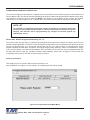
NOTE
?
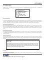
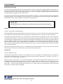
The input video level must be between 0.5V - 2.0V Peak to Peak. If the video is lower or not
present the VL LED will illuminate signifying low or no video and the VSI-Pro Max will have a
poor or no output video signal.
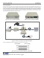
After completing the interface installation as described in the separate Installation Guide for your specific cash
register, computer, radar gun or other serial device, connect the video input source to the video input BNC on the
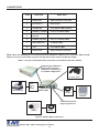
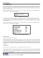
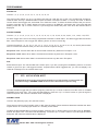
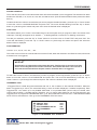
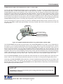
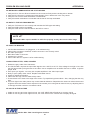
rear of the VSI-Pro Max. The BNC video output goes out to the video system (VCR, DVR, quad, switcher, multiplexer,
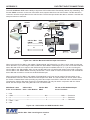
or monitor). This connection is shown in Figure 4. The video output from the VSI-Pro Max is 1[V] Peak to Peak into
a 75 [ohm] load. Most monitors or televisions with direct video inputs are terminated with a 75 ohm load. If the
monitor is not terminated, the VSI-Pro Max will still output 1[V] Peak to Peak. The VSI-Pro Max will be able to drive
two terminated loads without loss of video level.
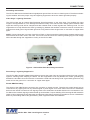
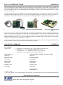
The VSI-Pro Max uses a 9-12VDC @300 [mA] UL/CSA power supply which must be plugged into the Power input on
the VSI-Pro Max’s Real Panel.
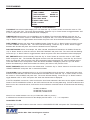
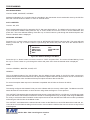
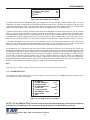
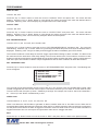
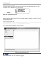
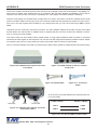
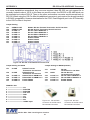
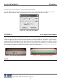
3.1 LED Indicators
Power
Register Data
Network LED
Video Error
Green Signifies power is supplied to the unit
Green This LED flashes whenever data is
received from the cash register
Red
This LED flashes whenever data is
sent or received on the Network Port
Red
This LED illuminates with the video
level is not present or too low
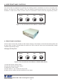
Figure 1: VSI-Pro Max Front Indicator LEDs and
Programming Pushbuttons
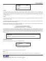
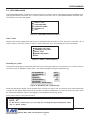
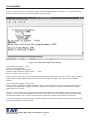
Figure 2: VSI-Pro Max RJ45 Network Connections
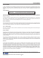
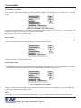
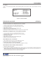
Figure 3: VSI-Pro Max Rear Connections
VSI-Pro Max POS / Cash Register Interface
10