1
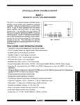
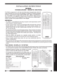
INSTALLATION INSTRUCTIONS 680-10 REMOTE AC SWITCHER The Model 680-10 is an IR Remote Controlled AC Switcher with six AC outlet receptacles. It accepts RC68+ (or RC68) IR Programmer commands coming from any Xantech IR receiver, keypad, or controller directwired to its IR Input port. Switching modes of ON, OFF, Toggle, Momentary and Group are possible. Each outlet is switched ON or OFF by a high current electromechanical relay for higher reliability than solid state switching methods. Sequential ON commands for each outlet are possible when used in conjunction with learning devices, such as Xantech URC-1 remotes, Smart Pads, or 590 controllers. Since the 680-10 has 30 installer-adjustable IR code groups, it allows multiple 680-10's to be individually controlled when used in the same system. OUTLET 1 5A MAX OUTLET 2 5A MAX IR OUTLET 3 5A MAX CONFIRM INPUT 680-10 REMOTE AC SWITCHER TOTAL LOAD LIMITED TO 15A RESET ➧ TEMPORARY POWER TAP CAUTION: TO REDUCE THE RISK OF ELECTRIC SHOCK USE INDOORS IN A DRY LOCATION. 120 VAC 15A MAX OUTLET 4 5A MAX OUTLET 5 5A MAX OUTLET 6 5A MAX FEATURES AND SPECIFICATIONS • Six AC Outlets rated at 120 VAC, 5 Amps each. . • 15 Amps total current rating. • Includes 15-Amp circuit breaker. • 14-Gauge heavy duty 3-conductor power cord, 5-1/2 feet in length, with a grounded 3-prong plug. • IR input jack (3.5mm mini phone jack) • An LED indicator lights to confirm the presence and acceptance of 680-10 IR commands. • Requires RC68+(or RC68) hand-held Programmer codes set to a matching IR code group. • The 680-10 is factory preset to code group 88. • Dimensions: 15-1/2" W x 4-1/2" D x 2-3/8" H.. RC68+ PROGRAMMER / REMOTE CONTROL The RC68+ (or RC68) Programmer (available separately) contains all the commands necessary to operate the 680-10 (see Fig. 2). • You will need it to program universal learning devices such as the Xantech URC-1 learning remote, the Xantech Smart Pads, the 590 Programmable Controller, the 710 Fone Link, etc., with commands that operate the 680-10. • NOTE: The RC68+ codes operate several other Xantech models as well, such as the RS41AV, CC12, ZPR68, etc. Therefore, only the button descriptions that apply to the operation of the 680-10 are listed in the Button Descriptions section. All others should be ignored. 1 Remote Control Switchers Fig. 1 Model 680-10 IR Remote Controlled AC Switcher CAUTION: While the RC68+ can be used as a handheld remote control, it is highly recommended it not be given to the final user for the following reasons: • Since it includes adjustable code groups, the user may inadvertently alter the installer configurations. • Also, since the user will require IR commands from other brands of equipment to control the total system, in addition to those of the 680-10, all commands should be consolidated into one learning device, for ease of use. APPLICABLE RC68+ BUTTON DESCRIPTIONS (With the "D" Overlay. Refer to Fig. 2) Outlet Numbers (1 through 6). These numbers identify the row of button commands that apply to each AC Outlet on the 680-10. Code Group Numbers. The 680-10 is capable of being set to 30 different IR code groups. The code groups are identified by the numbers and letters that are on the face of each button. NOTE: When shipped from the factory, the 680-10 is set to code group number 88. Be sure to set the RC68+ to the same number! It may be necessary to change the 680-10 to a different code group if it is used in a common IR bus controlled system with other Xantech 680-10's, to avoid mutual interaction. Refer to the RC68+ instructions for code group setting details and procedures! Outlet Command Modes. Depending on the installation, you may want to have the 680-10 respond to IR commands in different ways. The basic modes of operation for each outlet on the 680-10 are as follows: OFF -Turns the power OFF to the selected outlet. ON - Turns the power ON to the selected outlet. These dedicated OFF and ON commands are helpful when sending power commands "blind" from secondary rooms when you have no visual Outlet Numbers Place the "D" Overlay aid for status. (1 through 6) on the RC68+ TGL - (Toggle Mode) - Switches power ON to the selected outlet when the TGL command is sent and OFF when it is sent again. If the outlet is ON, Outlet Command it will turn OFF-- if it is OFF it will turn ON when Modes the code is sent. (for 6 outlets) MMT- (Momentary Mode) - Turns the selected outlet ON when the code is sent. The ON condition Group-ON remains only as long as the MMT code is being Group-OFF sent. The outlet is normally OFF. Code Group Numbers GP-ON (Group ON). - This button (labeled F8 on the (on face of each button face) causes the 680-10 to turn all 6 AC button) outlets ON at the same time. GP-ON overrides RC68+ all individual settings. NOTE: OFF, ON and TGL (toggle) operation for any individual outlet will still operate after Group ON is executed. Fig. 2 RC68 Programmer GP-OFF (Group OFF). - This button (labeled D8 on the button face) causes the 680-10 to turn all 6 outlets OFF (or any selected single outlet). D 1 2 3 4 5 6 80 48 10 90 OFF ON TGL MMT 00 C0 50 D0 OFF ON TGL MMT 40 A0 30 B0 OFF ON TGL MMT 20 E0 70 F0 OFF ON TGL MMT 60 88 18 98 OFF ON TGL MMT 08 A8 38 B8 OFF ON TGL MMT 28 E8 78 F8 01 41 21 61 09 29 69 GP-ON 68 C8 58 E1 89 C9 D8 A9 E9 49 71 19 59 39 79 F1 99 D9 B9 F9 GP-OFF 2 680-10 NOTE: The 680-10 should normally be plugged into an unswitched AC outlet. However, if the power to the 680-10 is turned off by a power failure, or other means, the internal memory will retain the last selected switched condition for each of the outlets. INSTALLATION Fig. 3 illustrates an installation where a 680-10 Remote AC Switcher, along with a 599-00 Pulsed Switching Module and a 590-00 Programmable Controller, provides the AC power management in a 4-zone system. It allows each zone AV receiver to be turned ON and OFF from their respective remote rooms with separate ON and OFF IR commands. This permits exclusive ON/OFF AC power switching without the need for knowing status. It also allows the common sources to be switched ON when the first zone AV receiver is turned on and OFF only when the last zone AV receiver is turned off. The system in Fig. 3 is configured as follows: 1. The AC cords of the zone AV receivers are plugged into outlets #1 through #4, respectively, on the 680-10. Each AV receiver's power switch is left at the ON position. NOTE: You must use AV receivers that remember their ON condition when their power cords are unplugged. (Most AV receivers now have this capability). 2. Outlets #1 through #4 on the 680-10 are sent separate ON and OFF commands. This means that outlet #1 will turn ON and OFF with the ON and OFF commands from row #1 on the RC68+ Programmer. Similarly, outlet #2 will turn ON and OFF with the ON and OFF commands from row #2 on the RC68+, and so on. Refer to Fig. 2. 3. In order to obtain power ON/OFF DC reference signals from each zone, a 786-00 power supply is plugged into an AC outlet (switched or un-switched) on the back of each AV receiver. These signals are paralleled and applied to the IN+ and IN– terminals of a 599-00 Pulsed Switching Module. The 599 then passes momentary ON and OFF pulses to input ports #1 and #2 on the 590 Programmable Controller. Similarly, the #2 port, when activated with an OFF pulse from the 599, causes the 590 to output a sequence of power OFF commands for the Satellite Receiver, the VCR and the RC68+ OFF command for outlet #6 on the 680-10. See the 590 instructions for programming procedures. CAUTION: If you find that the common source equipment does not turn ON consistently (or not at all), add a delay of approx. 1 second at the beginning of both the ON and OFF sequences in the 590. This can be done with one or two "dummy" commands (commands that do not operate any of the functions on the equipment in the installation). Without the delay, the initial ON or OFF command from the handhelds (or keypads) for the 680-10 to actuate the zone AV receivers may not have cleared the 680-10 sufficiently before the next command (from the 590) arrives to turn on the #6 outlet for the common source equipment. 5. The IR output from the 590 (O and G) is connected to one of the zone inputs (IN and G) on the 79520 Zone Controller. (Any one of the zone inputs can be used for this purpose). The 590 IR signal is then passed on to the 680-10 via one of the Common Emitter ports on the 795. 6. The common source components that can remember their ON condition when their power cords are unplugged, are all powered from the #6 outlet on the 680-10. Those that cannot, such as the VCR and the Satellite Receiver shown in Fig. 3, must be plugged into unswitched outlets and receive their IR power commands from the 590 through the 795 and the common emitters. 680-10 3 Remote Control Switchers 4. The 590 input ports #1 and #2 are programmed with a sequence of commands. The #1 port, when activated with an ON pulse from the 599, causes the 590 to output a sequence of IR power ON commands for the Satellite Receiver, the VCR and the RC68+ ON command (from row #6 on the RC68+) for outlet #6 on the 680-10. Micro Link™ IR Receivers Dinky Link™ IR Receiver 291-10 +12V 3-Wire Cable +12V IR OUT 7 Foot Quick Connect Cable GND GND Red Stripe +12V Do not use these jacks Smart Pad™ IR OUT X X CB12 Connecting Block GND IR RCVR GND J-Box IR Receiver IR OUT PWR OUT Red Stripe Hidden Link™ IR Receiver 780-10 +12 VDC IR OUT 3-Wire Cable ZONE 1 ZONE 2 J-BOX RECEIVER ZONE 3 480-00 780-10 ZONE 4 490-00 Series GND IR OUT +12V V G S 3-Conductor Cable (unshielded OK) 795-20 795-20 FOUR ZONE AMPLIFIED CONNECTING BLOCK Four Zone Amplified Connecting Block ZONE COMMON 10 9 8 7 6 5 4 3 2 1 IR ZONE ZONE 1 ZONE 2 ZONE 3 ZONE 4 ZONE 3 ZONE 2 ZONE 1 A A A A B B B B ZONE 4 +12 IN G +12 IN G +12 IN G +12 IN G POWER +12V 120 V AC (unswitched) Satellite Receiver To Zone 4 Emitter To Zone 3 Emitter To Zone 2 Emitter To Zone 1 Emitter 786-00 Emitter VCR To 120 V AC (Unswitched) 680-10 + OUTLET 1 5A MAX Zone 2 AC AV Receiver Zone 3 Zone 4 Emitter AV Receiver Zone 4 + + Zone 3 AC AC for "Power Line Switchable" Common Sources White striped side – + ZONE RECEIVERS Zone 4 AC OUTLET 3 5A MAX OUTLET 6 5A MAX AC Power Strip Zone 3 Emitter – OUTLET 2 5A MAX TOTAL LOAD LIMITED TO 15A OUTLET 5 5A MAX Mouse Emitters AV Receiver Zone 2 – Emitter 283M Blink-IR™ – Zone 2 Emitter Cassette DecK COMMON SOURCES AV Receiver Zone 1 ➧ RESET CD Changer Zone 1 Emitter Zone 1 AC OUTLET 4 5A MAX Emitter 782-00 Power Supply 120 VAC 15A MAX Remote AC Switcher Emitter Laser Disc Unregulated Power Supplies plugged into an AC outlet on each Zone Receiver OFF ON GND +12V 1 2 3 4 5 6 7 8 9 10 11 12 13 14 15 16 O G 12VDC – + 599-00 RES DEL SEQ PGM + Pulsed Switching Module PULSED SWITCHING MODULE 786-00 Power Supply IN+ IN– GND +12V Programmable Controller (back view) 1234 BANK IR CONFIRM TEMPORARY POWER TAP CAUTION: TO REDUCE THE RISK OF ELECTRIC SHOCK USE INDOORS IN A DRY LOCATION. 680-10 REMOTE AC SWITCHER 599-00 To 120 V AC (unswitched) 590-00 INPUT – 12VDC MAIN ROOM, EQUIPMENT CABINET, ETC. Fig. 3 A typical application of the 680-10 for AC switching in a 4-zone system. 6. The common source components that can remember their ON condition when their power cords are unplugged, are all powered from the #6 outlet on the 680-10. Those that cannot, such as the VCR and the Satellite Receiver shown in Fig. 3, must be plugged into unswitched outlets and receive their IR power commands from the 590 through the 795 and the common emitters. 7. The common sources are therefore switched ON when the first AV receiver is turned ON, and will remain on until the last AV receiver is turned OFF. 8. Finally, ON and OFF IR commands from the RC68+, for outlets #1 through #4, are "taught" into a learning remote, such as a Xantech URC-1, and into the Xantech Smart Pad, along with all other desired system commands, for total system operation. 9. To embellish the system further, you could add the GP-ON and GP-OFF commands from the RC68+ programmer to the keypads or the URC-1 remotes so that all zones may be turned ON or OFF from any zone location. See the 795-20 Installation Instructions for additional information regarding zoned systems MOUNTING The 680-10 has four attached rubber feet for stand-alone mounting. Underwriters Laboratories defines the 680-10 to be a moveable device and therefore it is not to be fastened down permanently to any surface. It 12-20-00 may however, be placed in any orientation to accommodate the installation. Rev.C 4 680-10