1
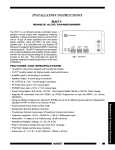
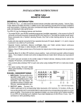
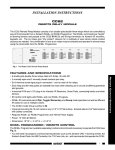
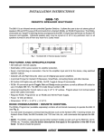
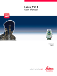
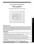
INSTALLATION INSTRUCTIONS RT16-10 ADDRESSABLE INFRARED ROUTER The RT16-10 is a ONE-IN/SIXTEEN-OUT IR switcher which directs an infrared control signal to any one of 16 output ports, any combination of ports, or all 16 as a group. You can control large groups of TV monitors (or any other A/V product) from control locations using Xantech IR Receivers or Smart Pads. Up to 16 devices may be addressed with one RT16-10. Additional RT-10's can be connected for control of larger numbers of devices, such as TV monitors in a sports bar, by using different IR code groups on each unit. The "I" and "G" output ports can drive LED indicators placed at each controlled device location so that you can see which devices are being addressed at any given time. Factory Installed Jumper. +12 G G S S DATA IN POWER 12 VOLTS 1 AMP D.C. IR RCVR INPUT O G G I O G G I O G G I O G G I O G G I O G G I O G G I O G G I 2 4 6 8 10 12 14 16 RT16 -10 • DATA OUT ID CODE SWITCH ADDRESSABLE IR ROUTER I = INDICATOR, O = OUTPUT, G = GROUND, S = SIGNAL 1 3 5 7 9 11 13 15 I G G O I G G O I G G O I G G O I G G O I G G O I G G O I G G O ON 1 2 3 4 5 6 Fig. 1 Model RT16-10 Addressable IR Router • GP-ON (group on) and GP-OFF (group off) codes from the RC68+ select and deselect all 16 ports together as a group. • The factory preset IR Code Group is 70. It can be installer changed by use of the RC68+ Programmer. • ID CODE SWITCH. Switches 2 ~ 6 of this 6 position DIP swtich are reserved for future enhancements. NOTE: The unit willnot operate with RC68+ IR control signals unless switches 2~6 are all set to the OFF psition. Switch 1 selects between single and multiple routing. OFF = Single Routing, ON = Multiple Routing. Address Switches Single/Multiple Routing Switch ON (1) - Multiple OFF (0) - Single ON ON (1) Contoller Select Switch ON (1) - CTR16 OFF (0) - RC68+ 1 2 3 4 5 6 OFF (0) Fig. 2 ID Code Switch • The DATA IN and DATA OUT modular jacks allow future cascading enhancements. • One IR input on a 4-terminal plug-in connector permits connection of any Xantech IR Receiver, Keypad, Controller, etc. • An LED, adjacent to the IR RCVR INPUT, flashes when any IR commands are received (not just those that are RT16-10 specific). • 16 IR "O" and "G" emitter outputs and 16 "I" and "G" indicator outputs are located on 16 plug-in connectors. • The "I" and "G" indicator outputs are current limited to 25 mA, allowing the direct connection of an LED without the need for a current limiting resistor. • Power Jack: 2.1mm. 12V DC @ 1 Amp. Requires one 782-00 Power Supply for each RT16-10. • Universal mounting fits 19" racks. • Dimensions: 19" x 3 1/2" x 1 1/4". • Weight: 1 lb. 3 oz. 1 Remote Control Switchers FEATURES AND SPECIFICATIONS •The RT16-10 requires the XANTECH RC68+ (or RC68) Hand Held Programmer codes, set to a matching IR Code Group, to address 16 ports individually or in any combination of groups. RC68 PROGRAMMER / REMOTE CONTROL The RC68+ (or RC68) Programmer (available separately) contains all the commands necessary to operate the RT16-10 (see Fig. 3). • You will need it to program universal learning devices such as the Xantech URC-1 learning remote, the Xantech Smart Pads, the 590 Programmable Controller, the 710 Fone Link, etc., with commands that operate the RT16-10. • NOTE: The RC68+ codes operate several other Xantech models as well, such as the RS41AV, CC12, ZPR68, etc. Therefore, only the button descriptions that apply to the operation of the RT16-10 are listed. All others should be ignored. CAUTION: While the RC68+ can be used as a handheld remote control, it is highly recommended it not be given to the final user for the following reasons: • Since it includes adjustable code groups, the user may inadvertently alter the installer configurations. • Also, since the user will require IR commands from other brands of equipment to control the total system, in addition to those of the RT16-10, all commands should be consolidated into one learning device, for ease of use. APPLICABLE RC68+ BUTTON DESCRIPTIONS (use Routing Commands (1 through 16). "C" overlay, Fig.3) The IR commands from these buttons cause the RT16-10 to route commands to any of the 16 corresponding IR outputs. For example, pressing button 5 (labeled 00 on the button face) on the RC68+ will cause the RT16-10 to route the IR signal through to the number 5 output. GP-ON (group ON). This button (labeled 60 on the button face) causes the RT16-10 to route IR commands to all 16 outputs at the same time. GP-OFF (group OFF). This button (labeled 88 on the button face) causes the RT16-10 to shut off all (or any smaller group of one or more) of the 16 outputs. Code Group Numbers. The RT16-10 is capable of being set to 30 different IR code groups. The code groups are identified by the numbers and letters that are on the face of each button. NOTE: When shipped from the factory, the RT16-10 is set to code group number 70. Be sure to set the RC68+ to the same number! It may be necessary to change the RT16-10 to a different code group if it is used in a common IR bus controlled system with other Xantech RT16-10's, to avoid mutual interaction. Refer to the RC68 instructions for code group setting details and procedures! IR ROUTING MODES The RT16-10 has the ability to direct IR control signals to any one of the 16 output ports, any combination of ports, or all 16 as a group as follows: 1. Single Routing An IR route to a single port (1 through 16) occurs when a corresponding RC68+ Hand Held Programmer code is sent. It remains on until a different routing command is sent or when the GP-OFF (group off) code is sent. This allows any individually selected port to be driven with a control signal separate from the others. ON (1) OFF (0) 0 ON Controller & Address Switches 1 2 3 4 5 6 ID CODE SWITCH Set #1 to OFF (0) 2 RT16-10 2. Multiple Routing IR routes can be established to any desired combination of ports (1 through 16) for simultaneous operation. This is useful if you wish to address smaller groups of units for special purposes. Simply press any desired combination of IR routes that you want (e.g., 2, 4, 5, 8, 11 & 16). Controller & Address Switches 1 ON (1) ON 1 2 3 4 5 6 OFF (0) ID CODE SWITCH Set #1 to ON (1) The chosen IR routes remain on, allowing you to control just the selected devices until the GP-OFF command from the RC68+ is sent. You may make up sequences (macros) in a learning device (such as the Xantech Smart Pads) for each routing combination you desire for rapid access to the controlled groups. Just remember to include the GP-OFF command at the beginning of each sequence. CAUTION: Each time you adjust switch 1 to select the desired Single or Multiple mode, you must remove power from the RT16-10 for a few moments for the change to take effect. C 80 Routing Commands (1 through 16) GP-ON GP-OFF 48 10 90 1 2 3 4 00 C0 50 D0 5 6 7 8 40 A0 30 B0 9 10 11 12 01 Place the "C" Overlay on the RC68+ 41 21 20 E0 70 F0 13 14 15 16 61 60 88 18 98 09 GP-ON GP-OFF Code Group Numbers (on face of each button) 08 A8 38 B8 29 28 E8 78 F8 69 68 C8 58 D8 49 E1 89 C9 A9 E9 71 19 59 39 79 F1 99 D9 B9 F9 RC68+ 3. GP-ON (Group On - all 16 as a group) Fig. 3 RC68 Programmer All 16 IR routes remain on until the GP-OFF command is sent. NOTE: GP-ON and GP-OFF work in both the Single and Multiple routing modes. Future Enahncements The ID CODE SWITCH permits specific addressing logic for future cascading enhancements. NOTE: Switches 2 ~ 6 must remain OFF (0) except when used with the RC68+ (or RC68) IR commands. CAUTION IR RCVR INPUT Connector (refer to Figs. 1 & 4) This 4-terminal input has electrical connections for +12V, G (chassis ground), GS (IR signal ground) and S (IR signal). The GS terminal is provided so that the IR signal ground can be isolated from the chassis ground. This helps prevent ground loop problems, etc., in complex system configurations. IR Receiver Input Connector on RT16-10 Factory Installed Jumper +12 G G S S IR RCVR INPUT Fig. 4 However, when powering IR receivers and keypads directly from the RT16-10, as in Fig. 5, you must leave the factory installed jumper wired between the G and GS terminals as shown. This provides the needed ground return for the IR signal. Remove the jumper only when powering IR source devices separately and there is a need for electrical isolation. RT16-10 3 Remote Control Switchers In this mode all 16 routes are chosen instantly with the GP-ON command. This is useful if you wish to quickly address all groups at the same time. INSTALLATION Fig. 5 illustrates a typical application where an RT16-10 is used to route IR control signals to 15 TV monitors. 1. For this example, it is assumed that Single Routing with Group ON and OFF is required. 2. Since only one RT16-10 is used in the system, the factory preset Code Group 70 can be used. The RC68+ Programmer is set to the same number. 3. The RC68+ commands 1 through 15 (see Fig. 3) will establish an IR route to each TV individually. The Group On command will route to all 15 TV's simultaneously. Subsequent IR commands specific to the TV's, such as channel Up/Down, then operate the functions of the TV or TV's addressed. 4. In this system, the RC68+ codes are "taught" to a Xantech URC type Learning Remote for use with the 780-10 J-box IR Receiver or to a Xantech Smart Pad. Other learning devices may be used provided they are capable of learning and outputting the RC68+ codes, with carrier, to the RT16-10. 5. When programming, begin by assigning 17 keys for the RC68+ commands to a keypad or learning device. Commands 1 through 15 for individual routing and 16 & 17 for the Group On and Group OFF commands. Next, assign the keys for the TV function commands, such as channel Up/Down. 6. Teach the commands into the assigned keys, following the instructions that come with the learning device. On the URC and the Smart Pad3, all these commands could go into one bank. 7. The "I and G" terminals on each of the output terminal jacks are provided so that LED indicators, placed near each TV Monitor (if desired) will give a visual indication of the currently controlled Monitor. Refer to Fig. 6. Use LED's with an operating current rating of 20 to 25 mA. Fig. 7 shows an alternate installation method. In this example, the coaxial cables are used to carry the IR control signals to the emitters on 15 TV monitors, along with the RF signals. This eliminates the need to run 2-conductor wire to each TV. 1. Using the Xantech "Xtra Link™" principle, CPL10 IR/RF Couplers are used to inject the IR signals onto the coaxial cable at the "head end" and extract them at the other end to drive the emitters at each TV monitor. 2. Fig. 7 also illustrates the use of a Xantech 789-44 Connecting Block for control of the TV/Video sources as well as the TV Monitors. Note that the 789-44 is powered from the RT16-10. 3. A Channel Plus DA500 RF Amp in the RF system overcomes the RF signal losses of the RF splitters and the long cable lengths. 4. NOTE: Be sure the long cable lengths between the CPL10 Couplers are connected to the terminals marked RF/IR as shown! 4 RT16-10 #15 TV MONITOR 283M #14 To Emitters on even numbered TV's TV MONITOR 283M #13 TV MONITOR 283M #12 TV MONITOR 283M #11 TV MONITOR White Striped Side (+) Using the RT16-10 for IR Con trol of 15 TV Monitors TV MONITOR 283M #7 TV MONITOR 283M #6 TV MONITOR 283M #5 TV MONITOR ID CODE SWITCH 283-00 #4 1 2 3 4 5 6 15 I G G O 13 I G G O 11 I G G O I G G O 9 7 #8 TV MONITOR 283M #3 TV MONITOR DATA OUT 283M #2 Fig. 5 TV MONITOR 283M I G G O 5 I G G O 3 1 I G G O ADDRESSABLE IR ROUTER #9 I G G O 16 G = GROUND, S = SIGNAL 14 O = OUTPUT, I = INDICATOR, O G G I 12 DATA IN +12V IR OUT GND Jumper between the G and G S terminals (see CAUTION, pg 2). POWER 12 VOLTS 1 AMP D.C. Smart Pad™ IR RCVR INPUT +12 G G S S White Striped Side (+) TV MONITOR 283M ON GND RT16 -10 • GND 10 8 O G G I O G G I 6 O G G I O G G I +12V IR OUT #10 Remote Control Switchers IR OUT 780-10 J-BOX RECEIVER +12 VDC O G G I 780-10 J-Box IR Receiver 4 Use additional Control Devices as needed. 2 Smart Pad™ O G G I O G G I 283M TV MONITOR 283M 782-00 Power Supply #1 TV MONITOR 283M Blink-IR™ Mouse Emitter MODEL RT16-10 ADDRESSABLE IR ROUTER RT16-10 7 I G G O 5 Fig. 6 I G G O RT16-10 Connecting LED Indicators to the "I" and "G" Terminals To Emitters on TVs LED Indicators – – + + – – + 2-conductor cable + 5 RF SIGNAL IR SIGNAL Source Control Emitters (if Needed) TV/Video Source TV/Video Source 2512 2-way Combiner IN DA500 RF AMP OUT To CPL10 Couplers for remaining 7 TV's 202-00 4-way RF Splitters (5 locations) To 7 TV's (duplicate of splitter and coupler system to left) MODEL RT16-10 ADDRESSABLE IR ROUTER Coaxial Cables RF/IR CPL10 RF IR CPL10 IR RF CPL10 RF/IR Monitor RF/IR IR 283M RF RF IR CPL10 RF/IR CPL10 IR RF Long Coaxial Cables TV Monitor Monitor RF/IR RF IR CPL10 RF/IR RF/IR RF 3 RF 1 2 3 4 5 6 ON ID CODE SWITCH TV TV TV Monitor DATA OUT POWER 12 VOLTS 1 AMP D.C. IR CPL10 RF/IR CPL10 IR 15 I G G O 13 I G G O 11 I G G O 9 I G G O 7 I G G O 5 I G G O Coupler (30 locations) I G G O RT16-10 • 1 ADDRESSABLE IR ROUTER 8 DATA IN CPL10 White Striped Side (+) I G G O 16 G = GROUND, S = SIGNAL I = INDICATOR, O = OUTPUT, 14 12 10 O G G I O G G I O G G I O G G I 6 4 2 IR RCVR INPUT O G G I O G G I O G G I +12 G G S S STATUS IR IN IR OUT RF/IR +12 VDC CPL10 IR GND RF/IR RF RF/IR RF/IR GND CPL10 IR CPL10 IR CPL10 IR RF/IR +12V RF RF RF RF/IR CPL10 IR 782-00 CPL10 IR RF RF/IR Smart Pad™ IR Emitters (17 locations) Power Supply TV TV Monitor Fig. 7 CPL10 IR White Striped Side (+) Connect Additional Control Devices to the 789-44 as needed. RF RF RF/IR IR RCVR CPL10 12VDC IR CONNECTING BLOCK RF EMITTERS 789-44 O G G I 6015900 3.5mm mono mini plug to stripped ends cable (16 locations) Monitor TV Monitor TV Monitor Using the coaxial cables going to each TV to carry the IR Control Signals. 11-7-00 6 RT16-10