1
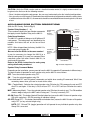
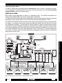
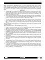
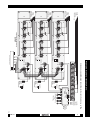
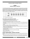
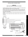
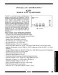
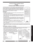
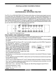
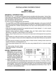
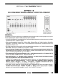
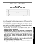
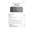
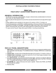
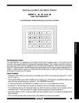
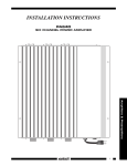
INSTALLATION INSTRUCTIONS
686-10
REMOTE SPEAKER SWITCHER
The 686-10 is an infrared remote controlled Speaker Switcher. It allows the user to turn six stereo pairs of
speakers ON and OFF by way of IR commands from a Xantech RC68+ (or RC68) Programmer. The RC68+
commands are "taught" to learning devices and passed to the 686-10 signal input terminals via Xantech IR
receivers and keypads. Individual speaker pairs may be turned on or off in any particular room or all
speakers turned on and off from any room for a "party mode".
PROTECTION
RESISTOR
SPEAKER
OUT
1
ON
ON
1 2 3 4 5 6
1 2 3 4 5
2
4
3
5
6
+12V
IR CONFIRM
GND
GND
RR+
LEFT
IR IN
L+
L-
AMPLIFIER
INPUT
IN
LEFT GND
RIGHT GND
RIGHT
686-10
REMOTE SPEAKER SWITCHER
12 VDC
Fig. 1 The Model 686-10 Remote Speaker Switcher
FEATURES AND SPECIFICATIONS
• 200 watts per channel capacity.
• Switchable 4-Ohm series resistor for amplifier protection.
• Isolated Left and Right Grounds allow use of bridging type power amplifiers.
• 4-terminal IR input for Xantech IR Receivers, SmartPads, connecting blocks and other devices.
• IR Confirm LED lights only with RC68+ On/Off, Toggle & Group IR commands.
• RC68+ IR commands permit Toggle, Pair and Group mode operations as well as different IR codes for
use of multiple 686-10's. The 686-10's Code Group number is 98.
• Universal mounting fits 19-inch racks or any 3-1/2" X 19" surface. Projects about 2-3/4 inches behind
panel with cables connected.
• Requires RC68+ Programmer (or an RC68) and 782-00 Power Supply.
• Power: 12 VDC @ 300mA.
• Dimensions: 19" W x 3-1/2" H x 2-1/4" D.
RC68 PROGRAMMER / REMOTE CONTROL
The RC68+ Programmer (available separately) contains all commands necessary to operate the 686-10
(see Fig. 2).
• You will need it to program universal learning devices such as the Xantech URC-1 learning remote, the
Xantech Smart Pads, the 590 Controller, the 710 Fone Link, etc., with commands that operate the 68610.
• NOTE: The RC68+ codes operate several other Xantech models as well, such as the RS41AV, CC12,
ZPR68, etc. Therefore, only the button descriptions that apply to the operation of the 686-10 are
listed. All others should be ignored.
®
1
Remote Control Switchers
• Seven 4-terminal plug-in connectors. One for the amplifier input and 6 for the stereo, relay-switched
speaker outputs.
CAUTION: While the RC68+ can be used as a handheld remote control, it is highly recommended it not
be given to the final user for the following reasons:
• Since it includes adjustable code groups, the user may inadvertently alter the installed configurations.
• Also, since the user will require IR commands from other brands of equipment to control the total system,
in addition to those of the 686-10, all commands should be consolidated into one learning device, for ease
of use.
APPLICABLE RC68 BUTTON DESCRIPTIONS
(With the "D" Overlay. Refer to Fig. 2)
Speaker Relay Numbers (1 ~ 6).
These numbers identify the row of button commands
that apply to each Speaker Relay on the 686-10.
Speaker Relay
Output
Numbers
(1 through 6)
Code Group Numbers.
NOTE: When shipped from the factory, the 686-10 is
set to code group number 98.
1
2
The 686-10 is capable of being set to 30 different IR
code groups. The code groups are identified by the
numbers and letters that are on the face of each
button.
Place the
"D" Overlay
on the RC68+
D
3
4
5
6
80
48
10
90
OFF
ON
TGL
MMT
00
C0
50
D0
OFF
ON
TGL
MMT
40
A0
30
B0
OFF
ON
TGL
MMT
20
E0
70
F0
OFF
ON
TGL
MMT
60
88
18
98
OFF
ON
TGL
MMT
08
A8
38
B8
OFF
ON
TGL
MMT
28
E8
78
F8
01
41
21
61
Speaker
Relay
Command
Modes
(for 6 relays)
09
29
69
Group-ON
49
Group-OFF
GP-ON
Code Group
Numbers
(on face of each
button)
68
C8
58
D8
GP-OFF
Be sure to set the RC68+ to the same number!
It may be necessary to change the 686-10 to a
RC68+
different code group if it is used in a common IR bus
controlled system with other Xantech 686-10's, to
avoid mutual interaction.
Refer to the RC68+ instructions for code group
Fig. 2 RC68+ Programmer
setting details and procedures!
Speaker Relay Command Modes.
Depending on the installation, you may want to have the 686-10 respond to IR commands in different ways.
The basic modes of operation for each speaker relay on the 686-10 are as follows:
OFF -Turns the selected speaker relay OFF.
ON - Turns the selected speaker relay ON.
These dedicated OFF and ON (paired) commands are helpful when sending IR commands "blind" from
secondary rooms when you have no visual aid for status.
TGL - (Toggle Mode) - Switches the selected speaker relay ON when the TGL command is sent and OFF
when it is sent again. If the relay is ON, it will turn OFF-- if it is OFF it will turn ON when the code is
sent.
MMT- (Momentary Mode) - Turns the selected speaker relay ON when the code is sent. The ON condition
remains only as long as the MMT code is being sent. The relay is normally OFF.
GP-ON (Group ON) - This button (labeled F8 on the button face) causes the 686-10 to turn all speaker relays
ON at the same time. GP-ON overrides all individual settings.
GP-OFF (Group OFF) - This button (labeled D8 on the button face) causes the 686-10 to turn all 6 speaker
relays OFF (or any selected single relay).
NOTE: OFF, ON and TGL (toggle) operation will still operate for any individual speaker relay after
Group ON is executed.
2
®
E1
89
C9
A9
E9
71
19
59
39
79
F1
99
D9
B9
F9
686-10
Power Interruption Status
The 686-10 should normally be plugged into an unswitched AC outlet. However, if the power to the 68610 is interrupted by a power failure or other reason, the internal memory will retain the last selected
switched status for each of the speaker relays.
INSTALLATION
Fig. 3 shows a typical application of a 686-10 in a multiroom system. The amplifier and speakers are
connected to the Model 686-10 by the four-terminal plug-in connectors.
The order of the stereo speaker pairs used is not important. If you have only two pair of speakers connected
to positions 5 and 6, they will work just as well as they would connected to positions 1 and 2.
The PROTECTION RESISTOR switch connects a four-Ohm resistor IN and OUT of a series connection with
the amplifier. The purpose of the resistor is to prevent loading the amplifier with less than four Ohms with
any combination of speakers. Since the 686-10 connects speakers in parallel, anytime two or more pair
of speakers are active the impedance would be less than four Ohms (a typical "eight-Ohm" speaker usually
has an actual impedance of less than eight Ohms somewhere between 20 Hz and 20 kHz). When all six
pair of eight-ohm speakers are active and the protection resistor is switched OUT, the parallel impedance
is less than 1-1/3 Ohms. With the resistor switched IN, the impedance will be less than 5-1/3 Ohms but
always more than four Ohms.
MAIN ROOM
Center
Speaker
Left
Speaker
SOURCE
COMPONENTS
Right
Speaker
Satellite Receiver
794/797
VCR
Universal Interface
From Preout, Signal
Processor Out, etc.
AV Receiver
(Version depends on
brand of AV receiver)
Mouse Emitters
IN
GND1
GND2
+12V
794
UNIVERSAL INTERFACE
SENDER/
EMITTER
1 (ON)
OUT
ON
1 2 3 4 5 6 7 8 910
0 (OFF)
1 2 3 4 5 6 7 8 9 10
+12V
XANTECH
Laser Disc
Stereo Power Amp
R
To 120 V AC
(unswitched)
L
RCA patch
cords
CD Changer
R+
782-00
R-
L- L+
686-10
Power
Supply
Remote Speaker Switcher
Cassette DecK
PROTECTION
RESISTOR
SPEAKER
OUT
ON
ON
1 2 3 4 5 6
1 2 3 4 5
2
1
4
3
5
6
IN
AMPLIFIER
INPUT
RR+
LEFT
LEFT GND
IR CONFIRM
RIGHT GND
RIGHT
IR IN
GND
GND
+12V
L+
L-
686-10
REMOTE SPEAKER SWITCHER
12 VDC
EMITTERS
791- 44
IR IN
S TAT U S
+12 VDC
HIGH
IR
OUT
GND
791-44
Amplified
Connecting
Block
AMPLIFIED
CONNECTING BLOCK
IR
RCVR
Speaker
Leads
(Home Runs)
12 VDC
3 Conductor Cables
for IR control signals
(Home Runs)
S-62/64/66
Wall Speakers
L
780-10
R
760-00
L
480-00
R
760-00
"J" Box Match Maker™
IR Receiver Vol. Control
Dinky Link ™ Match Maker™
Vol. Control
IR Receiver
REMOTE ROOM 1
REMOTE ROOM 2
L
R
Smart
Pad™
760-00
Match Maker™
Vol. Control
REMOTE ROOM 3
L
R
490DW-00
760-00
L
480-00
R
760-00
"J" Box Match Maker™
IR Receiver Vol. Control
Dinky Link ™ Match Maker™
IR Receiver
Vol. Control
REMOTE ROOM 4
REMOTE ROOM 5
L
R
Smart
Pad™
760-00
Match Maker™
Vol. Control
REMOTE ROOM 6
Fig. 3 A Typical System using the 686-10 Remote Speaker Switcher
686-10
®
3
Remote Control Switchers
282M or
283M
(To Multiroom
input jack on
AV receiver)
NOTE: When the 686-10 is connected to Xantech 760-00 Match Maker room volume controls, as shown
in Fig. 3, the PROTECTION RESISTOR is not necessary, since the Match Makers, when set correctly, will
provide the proper impedance match to the multiple speakers with virtually no power loss. In this case, be
sure the PROTECTION RESISTOR switch is set to the "OUT" position to prevent the waste of amplifier
power.
• • • IMPORTANT • • •
1. The Model 686-10 is intended to be mounted on a vertical surface so that the ventilation slots are at
the top and the bottom of the unit. Air should be allowed to circulate into the bottom slots and out of
the top slots, particularly when the PROTECTION RESISTOR is switched IN. The Model 686-10 will
mount onto a standard 19-inch rack.
2. Power Supply Considerations. Because of the high current requirement of the relays in the Model 68610, the Xantech Model 782 High Current Regulated Power Supply must be used. In Fig. 3, all of the
system IR control devices are also powered from the 782 through the 686-10.
To be sure you have sufficient power supply capability in your particular system, calculate the total
current required by using the method shown in the 791-44 instructions, then add 300 mA for the
686-10. If the total exceeds 1A, use a second supply to power the IR devices separately through the
791-44.
When the installation requires more than six sets of speaker pairs, two or more 686-10's may be connected
as shown in Fig. 4.
When using multiple 686-10's, keep the following items in mind:
1. Follow the instructions that come with the 760-00 Match Maker volume controls to ensure proper
impedance matching of all the speakers to the power amplifier.
2. Fig. 4 drives 18 stereo pairs, reflecting an impedance of 3.56 Ohms to the power amplifier (assuming
all speakers are 8 Ohms each and the 760's are all set to the 8X position). This is satisfactory provided
the amplifier you are using is safe into 3.56 Ohms. If not, you may need to switch the PROTECTION
RESISTOR to the IN position on one or more of the 686-10's, or use additional amplifier(s) to drive the
686-10's individually.
3. Remember, when you switch a PROTECTION RESISTOR IN, the volume level to the speakers will
be decreased.
4. When using multiple 686-10's or in combination with a 680-10 or other devices that respond to RC68+
codes, be sure each is set to a different IR CODE GROUP. Refer to Fig. 2 and the RC68+ Programmer
Instructions.
5. To perform Group ON and OFF with multiple 686-10's, it is necessary to sequence (macro) the different
ON and OFF codes for each 686-10 in a learning device, such as the Xantech URC-1 Remote, a Smart
Pad™, or a 590-00 Controller.
6. A CB18 Strip-IR Connecting Block is used in Fig. 4 to make the parallel connections from the IR
devices to the 791-44 Connecting Block. In this example, only 8 IR devices are shown connected to
the CB18. You would actually have to "double-up" on each of these connections if you need IR control
from all 18 rooms, or use an additional CB18.
4
®
686-10
CB18
HIGH
IR
OUT
IR
RCVR
EMITTERS
+12 VDC
GND
791- 44
2
12 VDC
AMPLIFIED
CONNECTING BLOCK
3
To 120 V AC
(unswitched)
To 120 V AC
(unswitched)
4
Power
Supply
782-00
Power
Supply
782-00
To 120 V AC
(unswitched)
Power
Supply
5
V G G S
V G G S
V G G S
V G G S
V G G S
V G G S
2-1-01
Rev.C
5
6
7
L+
L-
RR+
L+
L-
RR+
L+
L-
RR+
8
12 VDC
1 2 3 4 5
1 2 3 4 5 6
9
IN
OUT
IN
OUT
PROTECTION
RESISTOR
IR CONFIRM
ON
ON
12 VDC
1 2 3 4 5
1 2 3 4 5 6
IN
OUT
PROTECTION
RESISTOR
IR CONFIRM
ON
ON
12 VDC
1 2 3 4 5
1 2 3 4 5 6
PROTECTION
RESISTOR
L- L+
IR CONFIRM
ON
R-
ON
R+
Stereo Power Amp
Remote Speaker System Expansion with Multiple 686-10 Switchers
1
S TAT U S
AMPLIFIER
INPUT
AMPLIFIER
INPUT
AMPLIFIER
INPUT
782-00
V G G S
Fig. 4
Strip-IR
Parallel
Connecting
Block
(see text,
item 6)
Amplified
Connecting
Block
791-44
To Emitters
on
Source Equipment
IR IN
IR IN
GND
GND
+12V
IR IN
GND
GND
+12V
IR IN
GND
GND
+12V
®
V G G S
Remote Control Switchers
686-10
V G G S
1
1
1
2
2
2
686-10
3
3
3
RIGHT GND
RIGHT
LEFT GND
LEFT
SPEAKER
RIGHT GND
RIGHT
LEFT GND
LEFT
SPEAKER
RIGHT GND
RIGHT
LEFT GND
LEFT
SPEAKER
4
4
4
686-10
686-10
686-10
Remote Speaker Switchers
REMOTE SPEAKER SWITCHER
5
REMOTE SPEAKER SWITCHER
5
REMOTE SPEAKER SWITCHER
5
6
6
6
IR Control Leads
to Rooms
(Home
Runs)
Speaker Leads
to Rooms
(Home
Runs)
Speaker Leads
to Rooms
(Home
Runs)
Speaker Leads
to Rooms
(Home
Runs)