1
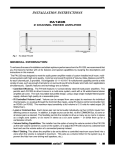
INSTALLATION INSTRUCTIONS RAT1 REMOTE AUTO TRANSFORMER The RAT1 is an infrared remote controlled stereo speaker volume control with impedance matching capability. It allows individual volume control of from one to 16 pair of stereo speakers from one stereo power amplifier, using one RAT1 for each stereo speaker pair. It is controlled with any Xantech IR Receiver or keypad or with Xantech MIRV1 motorized volume controls. The RAT1 maintains correct impedance matching between the amplifier and the speakers with the use of instant setting S1 to S8 jumpers, located on the unit. This eliminates the need for separate impedance matching devices in multi-room installations. RAT1 STATUS POWER S8 S4 S2 S1 IR IN STATUS GND +12 VDC REMOTE AUTO TRANSFORMER AMPLIFIER INPUT L+ L– R– R+ SPEAKER OUTPUT L+ L– R– R+ 12VDC Fig. 1 The RAT1 FEATURES AND SPECIFICATIONS • 10-position relay driven stepped auto transformer design. • Tri-Fi™ winding system for highest quality audio performance. • Amplifier Input: 4-screw plug-in connector. • Speaker Output: 4-screw plug-in connector. • IR, STATUS & +12V: 4-screw plug-in connector. • STATUS Input Jack: 2.1mm coaxial type. • POWER Input Jack (+12V): 2.1mm coaxial type. • Power Consumption: 300 mA @ +12V DC. Use Xantech Model 786-00 or 782-00 Power Supply. • Requires IR commands from the RC68+ (or RC68) Programmer or from the MIRV1, for volume operations. • Using the RC68+ Programmer, internal E2 PROM can be set to different group codes for independent operation of RAT1's when on a common IR bus. • Independent grounds between channels. • 75 watts per channel music power, 25 watts per channel continuous. • Frequency response: 20 Hz - 20,000 Hz ±1 dB at 1 Watt power input. • Attenuation: 10 steps at 3 to 6 dB per step, 35 dB maximum. • Impedance Multiplier Settings: S1, S2, S4, & S8. • Plug-in connectors accept wire sizes from 24 to 12 gauge. • "Flat Pack" design permits easy mounting. • Dimensions: 8" x 4-1/8" x 2-5/8" (203mm x 105mm x 67mm). 1 Speakers & Volume Controls • Factory preset Group Code number is 30. RC68 PROGRAMMER / REMOTE CONTROL The RC68+ (and the RC68) programmer (available separately) contains all the commands necessary to operate the RAT1. • You will need it to program universal learning devices such as the Xantech URC-1 learning remote, the Xantech Smart Pads, the 590 Programmable Controller, the 710 Fone Link, etc., with commands that operate the RAT1. • NOTE: The RC68+ codes operate several other Xantech models as well, such as the RS41AV, CC12, ZPR68, MIRV1, etc. Therefore, only the button descriptions that apply to the operation of the RAT1 are listed below. All others should be ignored. CAUTION: While the RC68+ can be used as a handheld remote control, it is highly recommended it not be given to the final user for the following reasons: • Since it includes selectable code groups, the user may inadvertently alter the installer configurations. • Since the user will require IR commands from other brands of equipment to control the total system, in addition to those of the RAT1, all commands should be consolidated into one learning device for easy use. APPLICABLE RC68+ BUTTON DESCRIPTIONS 1. IR Emitter Lens 2. Instant Volume Presets. These buttons allow direct preset activation of any of the 10 volume steps on the RAT1. Useful for "audio scene" ambiance settings for rooms or an instant partial mute action. 1 The relationship of the RC68 buttons to the RAT1 volume step positions is as follows: RC68+ Button RAT1 Volume Step # A, B, C 1 (OFF, MIN. VOL) ADJ-OFF 2 A B C ADJ-OFF 80 48 10 90 1 2 3 4 00 C0 5 50 6 INPUT 7 D0 A 01 2 41 8 40 A0 20 E0 30 70 B0 21 F0 TREBLE BASS Z-ADJ VOL 60 88 18 98 61 GLOBAL 1 3 3 09 MUTE 2 4 08 3 5 4 6 5 7 6 8 7 9 8 A8 38 ON 5 B8 29 E8 78 F8 LAST MAX-V TRIM 68 C8 58 D8 49 A9 E9 OFF E1 4 OFF 28 E-FLAT 69 C-BAL 89 C9 71 19 59 39 79 F1 99 D9 B9 F9 Fig. 2 The RC68+ Programmer 10 (MAX VOL) RC68+ PROGRAMMER 3. VOLUME Up/Down buttons. Each individual press will cause the RAT1 to increase or decrease volume level by one step, over a total of 10 steps. Each step causes a change of 3 to 6 dB. A maximum attenuation of 35 dB occurs at the lowest active step (#2). The lowest step (#1) switches the signal off. When buttons are held down, volume level changes continuously. 4. MUTE ON/OFF. Separate ON / OFF buttons mute and release the signal without knowing what the status is. This is very helpful in a remote room when all adjustments are made “blind” without any visual aid for status. NOTE: Mute is released (turned off) when a VOLUME or Preset Level button is pressed, in addition to MUTE OFF. 5. Code Group Numbers. If more than one RAT1 is used on a common IR controlled bus, or is included with other Xantech products that respond to RC68+ commands, different Code Groups can be assigned, by the installer, to avoid mutual interaction. Refer to the RC68+ instructions for Code Group setting procedures. NOTE: When shipped from the factory, the RAT1 is set to Code Group number 30. Be sure to set the RC68+ to the same number! 2 RAT1 SETTING THE IMPEDANCE MATCHING JUMPERS The impedance matching jumpers are located under a clear mylar cover on the right side of the top of the unit. Remove the two screws for access. The proper placement of these jumpers depends on the number of RAT1's and speakers used in the total installation. To set them for the best impedance matching condition, refer to the following charts and procedures: WHEN USING 8 OHM SPEAKERS Min. Amp. Impedance Number of Speaker Pairs Used 1 2 3 4 5 6 7 8 9 4 Ohms S1 S1 S2 S2 S4 S4 S4 S4 S8 8 Ohms S1 S2 S4 S4 S8 S8 S8 S8 10 11 12 13 14 15 16 S8 S8 S8 S8 S8 S8 S8 WHEN USING 4 OHM SPEAKERS Min. Amp. Number of Speaker Pairs Used Impedance 1 2 3 4 5 6 7 8 4 Ohms S1 S2 S4 S4 8 Ohms S2 S4 S8 S8 S8 S8 S8 S8 Procedure for all 4 Ohm or all 8 Ohm Speakers 1. Determine the rated speaker impedance (refer to the manufacturer's specifications - it must be the same for all speakers used in the system). 2. Determine the total number of stereo speaker pairs used in the installation. 3. Determine the minimum safe amplifier operating load impedance (refer to the manufacturer's specifications). 4. Find the correct jumper position from the above charts. 5. Place the jumpers in the same position on each RAT1 used in the system. Example 1: 13 pairs of 8 Ohm wall speakers are to be used with 13 RAT1's in a 13 room system, all driven by one amplifier rated for 4 Ohms minimum safe operating load impedance. 1. Refer to the chart "WHEN USING 8 OHM SPEAKERS". 2. Locate the number 13 in the top row. 4. The two jumpers therefore, one for each channel, need to be plugged onto the S8 pins on each RAT1 that feeds each room. Example 2: 3 pairs of 4 Ohm wall speakers are to be used with 3 RAT1's in a 3 room system, all driven by one amplifier rated for 8 Ohms minimum safe operating load impedance. 1. Refer to the chart "WHEN USING 4 OHM SPEAKERS". 2. Locate the number 3 in the top row. 3. On the third row, opposite "8 OHMS" and just below "3", note the letters "S8". These signify the required impedance multiplier. 4. The two jumpers therefore, one for each channel, need to be plugged onto the S8 pins on each RAT1 that feeds each room. RAT1 3 Speakers & Volume Controls 3. On the next row, opposite "4 OHMS" and just below "13", note the letters "S8". These signify the required impedance multiplier. Procedure for Speakers Other Than 4 or 8 Ohms In this case, treat all speakers that are rated between 4 and 7 Ohms as 4 Ohm speakers, and use the charts accordingly. Similiarly, all speakers that are rated 8 Ohms or higher, treat as 8 Ohms speakers. Again, all speakers used in the system should be the same impedance (i.e. all 6 Ohms, all 7 Ohms, etc.). Speaker Wire Recommendations As a rule of thumb, use good quality 18 gauge speaker wire for runs up to 30', 16 gauge up to 70', and 14 gauge up to 150'. The 4-terminal connectors accept wire sizes up to 12 gauge max. Procedure for Speakers of Differing Impedance Used in the Same System You may run into installations where you need to combine speakers of different impedance in the same system (8, 6, 4 Ohms, etc.). This is a more complicated situation that requires some calculation to obtain optimum results. You need to find the paralleled impedance for each group of speakers with the same impedance first and pick an "S" setting for each. Then check the overall paralleled "S" settings to see that the impedance is higher than the minimum safe value specified for the amplifier. Example 1: 2 pairs of 4 Ohm and 7 pairs of 8 Ohm wall speakers are to be used with 9 RAT1's in a 9 room system, all driven by one amplifier rated for 4 Ohms minimum safe operating load impedance. 1. Calculate the total paralleled impedance of the 4 Ohm group first, by dividing 4 Ohms by 2. 4 ÷ 2 = 2 Ohms. 2. Multiply 2 by 4 (for the S4 setting) = 8 Ohms. 3. Calculate the total paralleled impedance of the 8 Ohm group next, by dividing 8 Ohms by 7. 8 ÷ 7 = 1.14 Ohms. 4. Multiply 1.14 by 8 (for the S8 setting) = 9.12 Ohms. 5. Next, calculate the overall paralleled impedance with the following formulae: ZO = 1 ÷ [(1÷Z1) + (1÷Z2) + (1÷ZN...etc.)] ZO = overall paralleled impedance Z1 = 1st paralleled group after S setting Z2 = 2nd paralleled group after S setting ZN = additional paralleled groups, when used Since only two paralleled groups are used in this example, the calculation is as follows: ZO = 1 ÷ [(1÷8) + (1÷9.12)] = 4.26 Ohms. Since this yields more than 4 Ohms, the S4 setting for the 4 Ohm group and the S8 setting for the 8 Ohm group are the correct ones to use. Example 2: 2 pairs of 4 Ohm, 3 pairs of 6 Ohm and 7 pairs of 8 Ohm wall speakers are to be used with 12 RAT1's in a 12 room system, all driven by one amplifier rated for 4 Ohms minimum safe operating load impedance. 1. Calculate the total paralleled impedance of the 4 Ohm group first, by dividing 4 Ohms by 2. 4 ÷ 2 = 2 Ohms. 2. Multiply 2 by 8 (for the S8 setting) = 16 Ohms. 3. Calculate the total paralleled impedance of the 6 Ohm group next, by dividing 6 Ohms by 3. 6 ÷ 3 = 2 Ohms. 4. Multiply 2 by 8 (for the S8 setting) = 16 Ohms. 5. Calculate the total paralleled impedance of the 8 Ohm group next, by dividing 8 Ohms by 7. 8 ÷ 7 = 1.14 Ohms. 4 RAT1 6. Multiply 1.14 by 8 (for the S8 setting) = 9.12 Ohms. 7. Next, calculate the overall paralleled impedance ZO. Since three paralleled groups are used in this example, the calculation is as follows: ZO = 1 ÷ [(1÷16) + (1÷16) + (1÷9.12)] = 4.26 Ohms. Since this yields more than 4 Ohms, the S8 setting for the 4 Ohm group, the S8 setting for the 6 Ohm group and the S8 setting for the 8 Ohm group are the correct ones to use. Impedance Setting Tips 1. You may use the above method to calculate the correct impedance matching condition for practically any combination of speakers and RAT1s. 2. Use the lowest "S" setting possible consistent with the requirement to keep above the minimum safe operating load impedance for the amplifier. You may have to try 2 or 3 values of "S" for each impedance group and recalculate the overall paralleled impedance ZO each time, before you arrive at the final correct value. 3. When you test the system, you may find volume differences between the impedance groups when all RAT1s are set to max. volume. This is normal and is usually not a problem, since the user will be listening at lower levels most of the time. If you feel it necessary to even out the volume levels, move the "S" jumpers to the next higher number on the RAT1s that feed the loudest group. NOTE: While speakers of differing impedance can be accommodated using these procedures, it is highly recommended you not do so on a regular basis. The easiest and best performing installation is achieved by using speakers of the same impedance throughout the entire system. Then use the charts to determine the correct jumper "S" settings. INSTALLATION – COMMON IR BUS SYSTEM Fig. 3 illustrates a typical installation using three RAT1's along with other Xantech products in a 4-room multi-room system. The principles shown should be used as a guide when planning your own specific installations. It is configured as follows: 1. For simplicity, only three RAT1's are shown. Larger systems (up to a max. of 16 using 8-Ohm speakers) may be used. 16 is the maximum number using 8-Ohm speakers and an amplifier with a minimum loading impedance of 4 Ohms. See chart, in: Setting the Impedance Matching Jumpers section). 2. Note that a Common IR Bus connects the 780-80 "J" Box IR Receiver, the two MIRV1 Volume Controls, a 480-00 "Dinky Link" IR Receiver and a Smart Pad3 keypad to each of the RAT1's. In addition, it connects to a 789-44 Connecting Block, so that the source equipment can be controlled from the remote rooms. To make code group changes, refer to the RC68+ Programmer Instructions. NOTE: When shipped from the factory, the RAT1 and MIRV1 are set to code group number 30. If you use group 30 or change to a different number, be sure to always set the RC68+ to the same number. 4. When a code group is chosen, "teach" volume commands from the RC68+ Programmer (see Fig. 2) into learning remote controls (and the keypad), dedicated to each room. You may use the Xantech URC learning remote controllers for this purpose. NOTE: With a Common IR Bus system, you cannot carry the same remote control from roomto-room. You must use a dedicated remote for each room into which you have "taught" the specific RC68+ Code Group that operates the specific RAT1 that controls the volume for that room! RAT1 5 Speakers & Volume Controls 3. Since a common IR bus is used, each of the RAT1's and its connected MIRV1 (where used) must use a different IR Code Group number, so that the volume level in each room can be adjusted independent of the others. If you wish to carry remotes that have the same codes from room-to-room, use a Dedicated IR Bus System as shown in Fig. 4. 5. A 490-30 "Micro Link" IR Receiver plugs into the 789-44 for local control of the source equipment (i.e. equipment behind closed doors, etc.). 6. A "STATUS" system is included. This permits the power "ON/OFF" status of the A/V receiver or amplifier system to be visible in each of the remote rooms. It also permits the power management capability of the Smart Pad3 to operate. 7. The "STATUS" indicator LEDs on the 780-80 "J" Box IR Receiver, the two MIRV1 Volume Controls and the Smart Pad3, are powered by a 786-00 Power Supply plugged into a "SWITCHED" AC outlet on the A/V receiver or amplifier system. When the switched outlet is "ON", +12 Volts from the 786-00 passes through one of the 4 bus-conductors (STATUS line) to the LED indicators. NOTE: A resistor can be placed in series with the STATUS terminal at each IR receiver (IR receivers only, if so equipped) for adjustment of the brightness of the Status LED. See the specific installation instructions for the IR receiver for details. NOTE: When connecting system devices, be sure to carefully match up the terminals according to their markings as follows: IR IN (IR), STATUS (ST), GND (G) and +12VDC (V). Power Supply Considerations Up to 3 RAT1's plus associated MIRV1's and IR components can be used with one 782-00 Power Supply. (e.g. 9 RAT1's with associated components would require 3 of the 782-00 Power Supplies). Typical power supply connections are shown in Figs. 3, 4 and 6. 6 RAT1 MAIN ROOM, EQUIPMENT AREA, ETC. 786-00 "STATUS" power supply. Plug into a SWITCHED AC Outlet on A/V Receiver (see text). 490-30 CAUTION: Stereo receivers usually have two sets of speaker terminals, "A" and "B". Be sure all speakers connected to both "A" and "B" are taken into consideration when paralleling speakers, so that the amplifiers are not loaded by an impedance that is lower than that specified by the manufacturer. SPEAKER TERMINALS L + R - - + CONTROLLED COMPONENTS "Micro Link" IR Receiver (i.e. cabinet mounted for IR control in main room) Satellite Receiver 283M Blink-IR™ A/V RECEIVER, AMPLIFIER, ETC. (Back Panel) CD Changer 789-44 Connecting Block 782-00 Power Supply +12 VDC STATUS IR IN ® IR RCVR To 120 V AC (unswitched) 283M Blink-IR™ Mouse Emitter EMITTERS GND 789-44 (Place on FRONT Panel IR Sensor) CONNECTING BLOCK 12VDC 283M Blink-IR™ RAT1 #1 RAT1 #2 RAT1 REMOTE AUTO TRANSFORMER RAT1 STATUS POWER S8 S4 S2 S1 IR IN STATUS GND +12 VDC REMOTE AUTO TRANSFORMER AMPLIFIER INPUT L+ L– R– R+ SPEAKER OUTPUT L+ L– R– R+ 12VDC RAT1 #3 RAT1 S8 S4 S2 S1 L+ L– R– R+ STATUS 12VDC POWER S8 S4 S2 S1 POWER SPEAKER OUTPUT IR IN STATUS GND +12 VDC STATUS IR IN STATUS GND +12 VDC REMOTE AUTO TRANSFORMER AMPLIFIER INPUT L+ L– R– R+ AMPLIFIER INPUT L+ L– R– R+ SPEAKER OUTPUT L+ L– R– R+ 12VDC R L – – IR ST G V + + – 480-00 780-80 MIRV1 "J" Box IR Receiver Volume Control – + + – – + XANTECH IR ST G V "Dinky Link" IR Receiver ROOM 2 R L MIRV1 Volume Control ROOM 3 IR ST G V S-62/64/66 Wall Speakers Smart Pad3™ ROOM 4 Fig. 3 A RAT1 System Using a Common IR Bus RAT1 7 Speakers & Volume Controls + R L INSTALLATION – DEDICATED IR BUS SYSTEM Fig. 4 illustrates an installation where each remote room has a Dedicated IR Bus going to the RAT1 that controls it. The IR bus is not connected in common as it is in Fig. 3. This eliminates the need for dedicated remotes, allowing you to carry the same remote(s) from room-to-room. It is configured as follows: 1. Again, for simplicity, only three RAT1's are shown. Larger systems may be configured, using the same connection techniques (up to a max. of 16 RAT1's). 16 is the maximum number using 8-Ohm speakers and an amplifier with a minimum loading impedance of 4 Ohms. See chart on page 3. 2. Each Dedicated IR Bus connects the 780-80 "J" Box IR Receiver, the two MIRV1 Volume Controls, a 480-00 "Dinky Link" IR Receiver and a Smart Pad3 keypad to their respective RAT1's. 3. In order to control the common source components in a Dedicated IR Bus system, it is necessary to use a 793-00 Serial Control Combiner, connected as shown in Figs. 4 & 5. The 793 provides diode isolation between the IR signal lines but allows common operation of the source equipment through the 789-44 Connecting Block, as shown. Set the LOGIC POLARITY SELECTOR DIP switches on the 793 for "active high" operation - that is - all even numbered switches to "ON" - all odd numbered switches to "OFF". 4. The input and output ports on the 793 are 3.5mm mono mini jacks. Use matching mini plug cables with stripped ends when connecting. Polarity must be observed as shown in Fig. 5. For systems using more than five RAT1's, you will need additional 793-00's. These can be easily "daisy chained" as shown in Fig. 5. 5. Since a Dedicated IR Bus system is used, each of the RAT1's (and MIRV1's) can operate with the same IR Code Group number. In this case, the Code Group number, as received from the factory, should be used. NOTE: When shipped from the factory, the RAT1 (and MIRV1's) are set to Code Group number 30. Be sure to set the RC68+ to the same number! If a particular system requires a code group number change, refer to the RC68+ Programmer Instructions for code group setting procedures. 6. The desired volume commands from the RC68+ Programmer (see Fig. 2) need to be "taught" into learning remote controls and keypads used in the system. You may use the Xantech URC learning remote controllers for this purpose. 7. A 490-30 "Micro Link" IR Receiver plugs into the 789-44 for local control of the source equipment. 8. As in Fig. 3, a "STATUS" system is included. NOTE: When connecting system devices, be sure to carefully match up the terminals according to their markings as follows: IR IN (IR), STATUS (ST), GND (G) and +12VDC (V). Daisy-Chaining 793-00 Serial Control Combiners for Control of Common Components Fig.5 illustrates how two 793-00 Serial Control Combiners are "Daisy-Chained" to accommodate additional RAT's in a dedicated IR Bus System. This process can be repeated as necessary to accommodate the number of RAT's needed in the system. Simply connect the "B" CONTROL OUTPUTS port of the next 793 into the "A" CONTROL OUTPUTS port on the preceding 793 with a 3.5-to-3.5mm mono-mini cable as shown. NOTE: Be sure that all ten LOGIC POLARITY SELECTOR DIP switches on each 793 are set correctly. In this case, set them for "active high" operation - that is - all even numbered switches to "ON" - all odd numbered switches to "OFF". 8 RAT1 MAIN ROOM, EQUIPMENT AREA, ETC. 786-00 "STATUS" power supply. 490-30 Plug into a SWITCHED AC Outlet on A/V Receiver (see text). SERIAL CONTROL COMBINER 1 2 3 4 5 6 7 8 910 ON 789-44 A B CONTROL OUTPUTS 283M Blink-IR™ Mouse Emitter EMITTERS IR IN ® IR RCVR To 120 V AC (unswitched) 789-44 GND STATUS CONNECTING BLOCK +12 VDC 782-00 Power Supply CD Changer Connecting Block 12VDC 283M Blink-IR™ (Place on FRONT Panel IR Sensor) Satellite Receiver 283-00 Emitter LOGIC POLARITY SELECTOR 5 4 A/V RECEIVER, AMPLIFIER, ETC. (Back Panel) 3 + 1 - 2 R - CONTROL INPUTS L + 793-10 CAUTION: Stereo receivers usually have two sets of speaker terminals, "A" and "B". Be sure all speakers connected to both "A" and "B" are taken into consideration when paralleling speakers, so that the amplifiers are not loaded by an impedance that is lower than that specified by the manufacturer. SPEAKER TERMINALS CONTROLLED COMPONENTS "Micro Link" IR Receiver (i.e. cabinet mounted for IR control 793-10 Serial Combiner in main room) RAT1 #1 RAT1 #2 RAT1 REMOTE AUTO TRANSFORMER RAT1 STATUS POWER S8 S4 S2 S1 IR IN STATUS GND +12 VDC REMOTE AUTO TRANSFORMER AMPLIFIER INPUT L+ L– R– R+ SPEAKER OUTPUT L+ L– R– R+ 12VDC RAT1 #3 RAT1 S8 S4 S2 S1 L+ L– R– R+ STATUS POWER S8 S4 S2 S1 POWER SPEAKER OUTPUT IR IN STATUS GND +12 VDC STATUS IR IN STATUS GND +12 VDC REMOTE AUTO TRANSFORMER AMPLIFIER INPUT L+ L– R– R+ SPEAKER OUTPUT AMPLIFIER INPUT L+ L– R– R+ L+ L– R– R+ 12VDC 12VDC R L – – IR ST G + + – – R L + + – – V 480-00 780-80 MIRV1 "J" Box IR Receiver Volume Control ROOM 2 XANTECH IR ST G V IR "Dinky Link" IR Receiver + MIRV1 Volume Control ROOM 3 ST G V S-62/64/66 Wall Speakers Smart Pad3™ ROOM 4 Fig. 4 A RAT1 Dedicated IR Bus System RAT1 9 Speakers & Volume Controls + R L INSTALLATION (cont'd) 793-10 793-10 Serial Combiner CONTROLLED COMPONENTS Serial Combiner SERIAL CONTROL COMBINER 1 2 3 4 5 6 7 8 910 ON 4 3 2 793-10 LOGIC POLARITY SELECTOR 789-44 Connecting Block +12 VDC To IR IN and GND on each RAT1 White Stripped Side (+) ® + Use Mini-Plugto-Stripped end cables, Pt. # 6015900 IR RCVR To IR IN and GND on each RAT1 "Daisy-Chain" connection. Use 3.5/3.5mm MiniPlug cable, Pt. # 6017400 IR IN EMITTERS GND STATUS 283M Blink-IR™ Mouse Emitter 789-44 – CONNECTING BLOCK A B CONTROL OUTPUTS 1 1 2 3 4 5 6 7 8 910 ON LOGIC POLARITY SELECTOR CONTROL INPUTS 5 SERIAL CONTROL COMBINER 793-10 4 3 2 283M Blink-IR™ CD Changer 12VDC A B CONTROL OUTPUTS 1 CONTROL INPUTS 5 Satellite Receiver To additional Emitters if needed Fig. 5 Daisy-Chaining 793-00's in Multiple RAT1 Dedicated IR Bus Systems Driving Multiple Speakers From a Single RAT1 In some cases you may need to drive more than one set of speakers from a single RAT1, such as in large rooms or adjoining areas where common volume operation is acceptable. A typical system is shown in Fig. 6. RAT1 REMOTE AUTO TRANSFORMER 1. Use the same charts and rules for setting the impedance jumpers. In Fig. 6, all 8-Ohm speakers and an amplifier capable of handling an impedance of 4-Ohms, is assumed; resulting in a jumper setting of S1. AMPLIFIER INPUT L+ L– R– R+ SPEAKER OUTPUT L+ L– R– R+ 782-00 12VDC Power Supply To 120 V AC (unswitched) 786-00 Status Power Supply R L + 2. Note that two MIRV1's are used; one at one location in the room and the 2nd in another, for convenience of use. They both control the same volume level and track each other. POWER IR IN STATUS GND +12 VDC STATUS S8 S4 S2 S1 FROM AMPLIFIER SPEAKER TERMINALS – – R L + + – – + IR ST G V IR ST G V 780-80 MIRV1 MIRV1 "J" Box Volume IR Receiver Control Volume Control LARGE ROOM OR AREA Fig. 6 Driving Two Speaker Pairs From One RAT1 12-8-00 Rev.C 10 RAT1