1
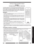
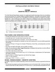
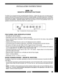
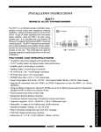
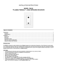
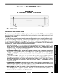
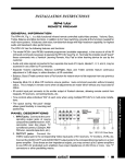
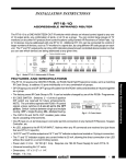
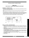
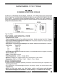
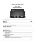
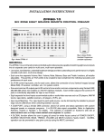
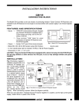
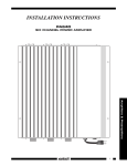
INSTALLATION INSTRUCTIONS CC12 REMOTE RELAY MODULE CC12 0 1 REMOTE RELAY MODULE 3 5 2 4 CODE SUBGROUP 6 7 The CC12, Fig. 1, is an IR Remote Controlled Double Pole Double Throw Relay Module. It provides dry contact closures to satisfy a variety of uses, such as activation of screen drops, projector lifts, etc. The switching is accomplished by way of infrared commands originating from a Xantech RC68+ Programmer (or RC68 Programmer). It can also be switched by a DC voltage applied between the CI (control input) and GND terminals. The RC68+ commands are "taught" to learning devices and passed to the IR IN, and GND input terminals of the CC12 signal input terminals via Xantech IR Receivers, Keypads and Connecting Blocks. N/C 1 IR IN CI GND N/O OFF = N/C ON = N/O +12VDC N/C 2 N/O IR CONFIRM FEATURES AND SPECIFICATIONS • One 6-terminal plug-in connector to make connection to the internal DPDT relay. • 5 Amp/30V DC relay contact rating. • 4-terminal IR input (S = IR Signal, CI = Control Input, G = Gnd, V = +12V) for connection of Xantech IR Receivers, Smart Pads, Connecting Blocks and other devices. • All plug-in connectors accept wire sizes from 24 to 12 gauge. • IR CONFIRM LED goes on only when an RC68+ (or RC68) IR command signal activates unit. • LED turns ON when N/O (normally open) contacts are closed and goes OFF when N/C (normally closed) contacts are closed. • Four RC68+ IR commands permit Pair, Toggle, and Momentary operation of the switching relay. • IR activated ON condition (N/O contacts closed) goes OFF if power is interrupted. • +3V to +30V DC 1 mA applied to CI terminal will switch unit, instead of IR, if desired. • Factory preset Group Code number: 50. • CODE SUB-GROUP switch allows a choice of 8 different groups of the four RC68++ commands that operate the CC12. This prevents mutual interaction in common IR systems when using more than one CC12 Also, internal E2 PROM can be set to different code groups, allowing up to 240 different IR code combinations if the system uses more than eight CC12's or in combination with SR21's. • Power: +12V DC @ 50 mA. Use the 781RG Power Supply for each CC12. If IR receivers or keypads are used on the same 12V line, use the 782-00 Power Supply. • Flanges, plus supplied screws, permits easy mounting to flat surfaces. • Dimensions: 5-1/4" x 2-3/8" x 1-7/8". 1 Remote Control Switchers Fig. 1 The CC12 RC68+ PROGRAMMER / REMOTE CONTROL The RC68+ Programmer (available separately) contains all the commands necessary to operate the CC12. • You will need it to program universal learning devices such as the Xantech URC-1 learning remote, the Xantech Smart Pads, the 590 Programmable Controller, the 710 Fone Link, etc., with commands that operate the CC12. • NOTE: The RC68+ codes operate several other Xantech models as well, such as the RS41AV, RP41AV, ZPR68, etc. Therefore, only the button descriptions that apply to the operation of the CC12 (OVERLAY 'B') are listed below. All others should be ignored. CAUTION: While the RC68+ will operate as a separate remote control, it is highly recommended it not be given to the final user for the following reasons: • Since it includes setable code groups, the user may inadvertently alter the installer configurations. • Also, since the user will require IR commands from other brands of equipment to control the total system, in addition to those of the CC12, all commands should be consolidated into one learning device, for ease of use. APPLICABLE RC68+ BUTTON DESCRIPTIONS 1. Pair OFF Command. This button activates the IR command that turns the internal relay of the CC12 to the OFF position (the N/C CODE SUBselection). GROUP . 2. Pair ON Command. This button activates the IR command that turns the internal relay of the CC12 to the ON position (the N/O selection). 3. TGL (toggle) Command. The first press of this button turns the relay ON (the N/O selection) - the second press turns it OFF (the N/C selection). 4. MMT (momentary) Command. Pressing this button causes the CC12 relay to go ON (the N/O selection) but stays ON only as long as the button is held down. When released, the relay returns to the OFF position (the N/C selection). 1 5 2 3 4 B 0 0 1 1 80 OFF 2 2 3 3 4 4 5 5 6 6 7 7 48 ON 10 TGL 90 01 MMT 00 C0 50 D0 OFF ON TGL MMT 40 A0 30 B0 OFF ON TGL MMT 20 E0 70 F0 OFF ON TGL MMT 60 88 18 98 OFF ON TGL MMT 08 A8 38 B8 OFF ON TGL MMT 28 E8 78 F8 OFF ON TGL MMT 68 C8 58 D8 OFF ON TGL MMT E1 89 C9 A9 41 21 Place the "B" Overlay on the RC68+ 61 09 RC68+ 29 69 49 6 E9 71 19 59 39 79 F1 99 D9 B9 F9 5. IR Emitter Lens. CODE SUB-GROUP Fig. 2 The RC68 Programmer The RC68+ has 11 rows of 5 buttons each. Each row, identified by the numbers 0 through 7 (see Fig. 2), will execute the same set of 4 commands listed above, when selected by the CODE SUB-GROUP switch on the CC12. This is useful to prevent mutual interaction in common IR systems when using more than one CC12, or if SR21's are used with CC12's. To change the CODE SUB-GROUP, simply rotate the CODE SUB-GROUP switch on the CC12 to the number that corresponds to the desired row on the RC68+. Remove and reapply power (after 20 seconds), then use the chosen row to execute the commands for that particular CC12. NOTE: No changes are needed on the RC68+! 6. Code Group Numbers. The CC12 is also capable of being set to different basic code groups as well as the sub-groups. NOTE: When shipped from the factory, the CC12 is set to code group number 50. Be sure to set the RC68+ to the same number! It may be necessary to change the CC12 to a different code group if it is used in a common IR bus controlled system with many CC12'S, SR21's, etc., to avoid mutual interaction. Refer to the RC68+ instructions for code group setting procedures. 2 CC12 INSTALLATION The CC12 can be used in any application that requires dry switch closures activated by IR commands or by a DC control voltage; up to the capacity of the DPDT 5A/30V DC relay. Some of the more likely applications would be to activate video projector lifts, screen drops, drape pulls, etc., in home automation systems. Fig. 3 is a simple example of a screen drop application. 782-00 780-80 Power Supply "J" Box IR Receiver +12 VDC IR IN IR RCVR 4-Conductor Cable (Unshielded OK) To Emitters on Other Controlled Equipment EMITTERS GND STATUS 789-44 +12VDC GND STATUS IR OUT CONNECTING BLOCK 12VDC To 120 V AC (unswitched) 789-44 Connecting Block CC12 Remote Relay Module 6 7 REMOTE RELAY MODULE PROJECTION SCREEN CONTROLLER 5 3 4 (To +12V System Status Voltage, if desired). Hand Held Learning Remote CC12 0 1 2 CODE SUBGROUP N/C MOMENTARY 1 IR IN CI N/O OFF = N/C ON = N/O GND UP N/C GND 2 +12VDC N/O IR CONFIRM DOWN Fig. 3 Using a CC12 to Activate a Projector Screen Drop • Fig. 3 assumes that the projector screen controller can be configured to operate with a momentary switch closure action. That is, a momentary closure and release at its control terminals will cause the screen to drop to its fully extended position. A second momentary closure will cause it to retract to its fully withdrawn position. • A 780-80 "J" box IR Receiver is shown for IR control of the system. Any of the other Xantech IR Receivers or keypads could also be used, depending on your system and aesthetic requirements. The STATUS LED indicator in the 780-80 can be driven by a +12V System Status (ON/OFF) voltage, such as from an adapter plugged into the Switched AC outlet on the system A/V receiver. • The 782-00 powers the IR receiver as well as the CC12 through the 789-44 Connecting Block. • Fig. 4 illustrates how both a screen and a projector lift can be operated at the same time. • Since the CC12 incorporates a DPDT relay, we can utilize the other half of the relay to perform dual operations, such as this, provided each operation can be carried out simultaneously. 782-00 780-80 Power Supply +12 VDC IR IN PROJECTION SCREEN CONTROLLER UP EMITTERS STATUS To Emitters on Other Controlled Equipment MOMENTARY 789-44 GND IR RCVR 4-Conductor Cable (Unshielded OK) CONNECTING BLOCK To 120 V AC (unswitched) +12VDC GND STATUS IR OUT 12VDC "J" Box IR Receiver 789-44 Connecting Block GND DOWN CC12 5 4 (To +12V System Status Voltage, if desired). VIDEO PROJECTOR LIFT CONTROLLER REMOTE RELAY MODULE 3 Hand Held Learning Remote CC12 0 1 2 CODE SUBGROUP 6 7 Remote Relay Module N/C CI GND MOMENTARY 1 IR IN N/O OFF = N/C ON = N/O +12VDC UP N/C 2 GND N/O IR CONFIRM DOWN Fig. 4 Simultaneous Operation of a Screen and Projector Lift Using a CC12 CC12 3 Remote Control Switchers • You would then program one button on the Handheld Learning Remote with the MOMENTARY(MMT) command from the RC68+ (or RC68) Programmer. Refer to Fig. 2. • Note that, as in Fig. 3, the N/O (normally open) contacts are connected to the screen and projector lift's MOMENTARY terminals. This allows the momentary action to occur. • As a practical matter, it will be necessary to see that the projector and the screen positions are both UP prior to the issuance of the first command. This will ensure that their actions will be synchronized so that they will both travel in the correct direction when activated. To overcome the possibility of incorrect synchronization, a method utilizing separate UP/DOWN paired commands is illustrated in Fig. 5. • Fig. 5 assumes that the screen, projector lift, motorized drapes, etc., have inputs that will execute the desired action with constant ON or maintained switch closures. • The N/C (normally closed) terminals, in this case, are connected to the UP terminals on each of the controllers, thus placing a maintained closure on them for the UP position. Connecting Block Power Supply "J" Box IR Receiver To 120 V AC (unswitched) +12 VDC STATUS IR IN 4-Conductor Cable (Unshielded OK) PROJECTION SCREEN CONTROLLER To Emitters on Other Controlled Equipment MOMENTARY UP EMITTERS GND 789-44 CONNECTING BLOCK +12VDC GND STATUS IR OUT IR RCVR GND DOWN CC12 Remote Relay Module 6 7 5 4 N/C To +12V System Status Voltage, (if desired). Hand Held Learning Remote VIDEO PROJECTOR LIFT CONTROLLER REMOTE RELAY MODULE 3 CODE SUBGROUP CC12 0 1 2 • For this type of operation, you would program one button on the Handheld Learning Remote with the Pair OFF command (UP) from the RC68+ Programmer, and a 2nd button with the Pair ON command (DOWN). See Fig. 2. 789-44 782-00 780-80 12VDC • Similarly, the N/O (normally open) terminals are connected to the DOWN terminals on each of the controllers. A maintained closure on them, when activated, will execute the DOWN position. CI GND MOMENTARY 1 IR IN N/O OFF = N/C ON = N/O +12VDC UP N/C GND 2 N/O IR CONFIRM DOWN Fig. 5 Connections for Execution of Paired Commands In this way, positive UP/DOWN commands can be issued without any possibility of confusion. Using the Voltage Controlled Input (CI) on the CC12 The CC12 Relay can be operated with a DC control voltage at the CI terminal, instead of IR, if desired. This allows the switching of high current systems (up to 5 Amps) with a low current DC control signal. • In Fig. 6, the STATUS (or CO output) of a ZPR68 (+12V) drives the CI (control input) of a CC12 when the zone is turned ON & OFF. (The common CO of the ZPR68 could also be used). • A 781RG powers the CC12 as well as supplying the needed +12V to activate the controlled device. If more than 200 mA is required to operate the controlled device, then a higher current power supply must be used, such as the 782-00 (12V, 1A). 781RG Power Supply 6 7 Remote Relay Module CC12 0 1 5 CODE SUBGROUP REMOTE RELAY MODULE 2 ZONE CONTROL - IR INPUTS CC12 To 120 V AC (unswitched) 4 Zone Control - IR Inputs section N/C +12V IR IN GND CI STATUS IR IN CONTROLLED AC POWER STRIP, LIFT CONTROLLER, ETC. 3 ZPR68-10 GND 1 N/O OFF = N/C ON = N/O + (3 to 30V DC) + N/C 2 +12VDC N/O IR CONFIRM Fig. 6 1-29-01 Rev.E 4 CC12