1
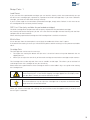
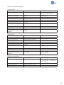
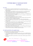
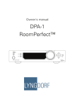
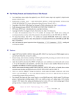
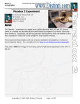
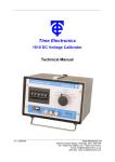
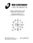
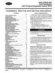
Owner´s manual
Millenium ADC
Analog/Digital Converter
2
Table of Contents
Unpacking the Millennium ADC
4
Operating Voltage
4
Serial Number Registration
4
Introduction
5
Accessories
6
Front Panel
7
Rear Panel
8
Remote Control
9
Setup Cartr.: 1
- Load Preset
- DSP Cart. Filter
- 50 kHz Zero
- Cartridge Gain
- Cartr. Balance
- Cartr. Capacit.
- Cartr. Impedance
- Polarity
15
15
15
15
15
17
17
17
17
Analog Input 1- 4 Menus
- Input Gain
- Polarity
18
18
18
19
19
19
19
20
20
20
Placement
10
Millennium Link Connection
10
Menu Tree
11
Technical Specifications
- Analog Inputs
- Phono Inputs
- Millennium Interface
- Digital Outputs
- Mains
- Mechanical
Menu Operation
12
Cleaning and Maintenance
21
Common Menus
- Digital Sample Rate
- Communication Address
- Communication Speed
- Display Timeout
- Remote Control
- Factory Reset
13
13
13
13
13
13
13
Technical Assistance
21
Phono Input Menus
- High Pass Filter
- De-emphasis
- Select Cartridge
14
14
14
14
3
Unpacking the Millennium ADC
Carefully remove the unit and accessory kit from the carton, visually check for shipping damage. Contact
both the shipper and your Lyngdorf Audio dealer immediately if the unit bears any sign of damage from
mishandling. All Lyngdorf Audio equipment is carefully inspected before leaving our factory.
Keep shipping carton and packing material for future use or in the unlikely event that
the unit needs servicing. If this unit is shipped without the original packing, damage
could occur and void the warranty.
Operating Voltage
The Millennium ADC is selectable to one of the following power ratings:
110V-120V~ at 50-60Hz with a power rating of 50W
220V-240V~ at 50-60Hz with a power rating of 50W
Connect the power input only to the AC source matching the setting shown on the
voltage selector switch. The warranty will not cover any damage caused by connecting to inappropriate AC mains.
The Millennium ADC has three power modes:
1. OFF
After Power off or Standby, the settings of Millennium ADC are retained. Please note that some parts
of the mains entry section still carry live mains.
2. STANDBY
In standby mode the Lyngdorf logo will be dimly lit.
3. ON
In on mode the Lyngdorf logo will be fully lit.
Serial Number Registration
Please record the serial number of your product here for future reference. The serial number is engraved in the plaque on the Millennium ADC rear panel. You will need this serial number, should you
ever require service on your Millennium ADC.
Millennium ADC serial number: _____________________
4
Introduction
Congratulations on your investment in the Lyngdorf Audio Millennium ADC (Analog to Digital Converter).
The Lyngdorf Audio Millennium ADC is a high-performance 2-channel Analog to Digital Converter with
4 line inputs. Using a combination of state-of-the-art analog circuitry and Digital Signal Processing to
support the two balanced 24 bit converters per channel, the Millennium ADC sets new performance
standards for analog to digital conversion.
The optional Lyngdorf Audio Phono Stage is a plug-in module for the Millennium ADC that allows a
gramophone to be connected directly to the Millennium ADC.
The RIAA equalization in the Lyngdorf Audio Phono Stage is implemented with tight-tolerance polypropylene capacitors. To further improve de-emphasis possibilities, an additional 7 de-emphasis curves are
available in the DSP for optimal playback of records made before implementation of the RIAA (Record
Industry Association of America) standard.
5
Accessories
You should find the following accessories included:
Mains cord
1
2
4
5
7
8
9
digital
0
info
3
6
menu
analog
AMP
RCS
CD
channel
TUNER
volume
ENTER
A/B
random
repeat
Remote control
6
Millennium Link cable
(5 pin XLR)
RS-232 cable for firmware
upgrade from a PC
Front Panel
1
2
3
4
5
6
Figure 1: Millennium ADC front panel.
The buttons/controls on the front panel of the TDAI 2200 can all be operated either with direct presses
or by operating the corresponding keys on the supplied remote control. All the keys on the front panel
[except the Mains switch (1)] are duplicated on the remote control as well.
1. Mains switch
Turns the power to the Millennium ADC on or off.
2. Left control button.
Multifunction button for switching the product on/off, input selection and menu operation:
• On/Stand by: Press to switch the Millennium ADC on from stand by. Press and hold the button to
switch back to standby mode.
• Input Selection: When the unit is switched ON press to toggle down
• Menu Operation: Down/back button. Press to use the down function. Press and hold to use the
return function. See chapter 9.b, Menu Operation, for a more detailed description.
3.
Display.
4. Lyngdorf logo.
Dimly illuminated in standby mode. Brightly illuminated when the Millennium ADC is on.
5.
Receiver for the infrared remote control.
6. Right control button.
Multifunction button for switching the product on, input selection and menu operation:
• On: Press to switch the Millennium ADC on from stand by.
• Input Selection: When the unit is switched ON press to toggle up
• Menu Operation: Up/select. Press to use the up function. Press and hold to use the select function.
See chapter 9.b, Menu Operation, for a more detailed description.
7
Rear Panel
2
1
3
5
4
PHONO GROUND
Millennium ADC
Phono Stage
L
R
6
7
8
9
10
11
12
13
Figure 2: Millennium ADC rear panel.
1.
Binding post for phono ground.
2.
Optional phono stage module.
3.
Millennium ADC serial number label.
4. RS-232 AUX and INPUT RJ45 connectors.
The RS-232 communication connectors are for connection to a computer for firmware upgrade. Please
visit www.lyngdorf.com for instructions and available firmware.
5. Mains voltage input selector.
Selects the correct voltage for your location. This switch selects either 110-120 V or 220-240 V operation.
Always check that the correct voltage has been selected prior to connecting this unit
to an AC power source. Failure to do so may result in serious damage to the unit.
The warranty will not cover any damage caused by connecting to inappropriate AC
mains.
6.
Phono input RCA connectors.
7.
Unbalanced analog input RCA connectors.
8.
Balanced analog input XLR connectors.
9.
Unbalanced digital output RCA connector.
10. Balanced digital output XLR connector.
11. Optical digital output Toslink connector.
12. Lyngdorf Audio Millennium Link XLR 5 pin connector.
13. Mains input IEC 320 connector.
8
Remote Control
The remote control is used to access the menu system and replicate the buttons directly accessible on
the front panel.
The four buttons used for selecting which device to control are described below. To control the Millennium ADC the AMP key should be pressed.
The functionality of the remote control depends on the products in your set-up. The
below description applies to operation of the Millennium ADC only.
1. Standby
Toggles between on and stand-by mode.
2. Numerical buttons
No function.
3. Info
Shows the firmware version of the Millennium ADC.
1
1
2
3
4
5
6
7
8
9
digital
0
info
3
menu
5
2
4
analog
6
4. Digital / Analog
No function.
7
7. AMP
Sets the remote for operation of the Millennium ADC
as well as a Lyngdorf Millennium MK III/IV Amplifier.
CD
channel
TUNER
10
volume
12
13
14
ENTER
15
6. Mute
No function.
RCS
8
11
5. Menu
Enters or exits the menu system.
9
AMP
16
A/B
random
repeat
8. RCS
No function.
9. CD
Sets the remote for operation of a Lyngdorf CD Player.
10. Tuner
No function.
11. Channel -/+
Toggles down/up between inputs.
14. Left / Right arrows
Navigation / adjustment in the menu system
Pressing and holding the buttons changes the
setting in some menus fast. E.g. Input Gain.
12. Volume Up / Down
No Funtion.
15. Enter
Selection in menu system.
13. Up / Down arrows
No Funtion.
16. Play/Pause, Stop, Skip etc.
No function.
9
Placement
The Millennium ADC should be placed well away from any source of magnetic fields like wall mains
adapters. Also avoid placing on top of a power amplifier – instead place them ‘side by side’.
Figure 3. Recommended placing of the Millennium ADC.
Millennium Link Connection
By using the Millennium Link Connection between the Millennium ADC and a Millennium MkIII or MkIV
amplifier (from firmware version 40) you are ensured the best possible integration of the two products
– both in terms of sound quality and ease of use. They become ‘one product’.
Connection:
1. Connect the two using the enclosed 5 pin XLR cable
2. Select the desired sample rate 48, 96 or 192 kHz. Please refer to the ‘Sample rate’ menu (9.c.i) of
this manual.
3. Set the Millennium ADC remote control menu to ‘Mill’ to let the Millennium amplifier control
operations (when you change the analog inputs on the Millennium amplifier, you will actually change
the inputs on the Millennium ADC). Please refer to the ‘Remote control’ menu (9.c.v) of this
manual.
Millennium MkI and MkII are not compatible with the Millennium Link Connection. In this case you have
two options:
1. Connect the two using one of the digital outputs:
• Unbalanced digital output RCA connector (SPDIF)
• Balanced digital output XLR connector (AES)
2. Update your MkI/II to a MkIII version
• Please contact your local Lyngdorf Audio dealer for further information.
10
Menu Tree
Common Menus
Main Menu ADC
Input Related
Menus
Input Related
Menus
Dig. Samplerate
Comm. Address
Comm. Speed
Display Timeout
Remote Control
Factory Reset
Phono Input Menus
Main Menu ADC
Common
Menus
High Pass Filter
De-emphasis
Select Cartridge
Setup Cartr. : 1
Polarity
Exit Main Menu
Phono Cartridge: 1
Load Preset
DSP Cart . Filter
50 kHz Zero
Cartridge Gain
Cartr. Balance
Cartr. Capacit .
Cartr. Impedance
Exit Cartr. Menu
Analog Input 1 – 4 Menus
Main Menu ADC
Common
Menus
Input Gain
Polarity
Exit Main Menu
11
Menu Operation
In the following the general menu operation is described with Display Timeout menu (used as an example only).
The menus available depend on the selected input. All settings outside the common
menus apply to the selected input only. Please refer to the menu tree.
When The Millennium ADC is switched on select the menu by pressing and holding the right control button until the menu appears or press Menu on the remote control.
Main Menu ADC
Input Gain
<
>
Pressing the Left / Right control buttons or Left / Right Arrow on the remote control toggles forwards /
backwards between the different menus. When the requested menu is reached (in this case the Display
Timeout menu).
Main Menu ADC
<
Display Timeout
>
Press and hold the right control button or press Enter on the remote control to access this menu.
Display Timeout
Curr: Off New: Off
Now the setting can be adjusted by pressing the Left / Right control buttons or Left / Right Arrow on the
remote control until the desired setting is reached. In this case Display Timeout is set to ‘On’.
Display Timeout
Curr: Off New: On
To save the setting press and hold the right control button until the previous menu re-appears or press
Enter on the remote control.
Pressing and holding the left control button or pressing Menu on the remote control, at any time, will
exit the menu completely. If the actual setting was not saved first, you will exit the menu without saving
the setting.
The Millennium ADC will automatically exit the menu if it has not been operated for
approximately 30 seconds.
12
Common Menus
Digital Sample Rate
Available sample rates are 48, 96 and 192 kHz.
Choice of sample rate depends on the compatibility with the actual amplifier. If your amplifier accepts all
sample rates, we recommend you to test the different settings to find your personal preference. This is
due to the fact that there is no simple answer as to what will result in the ‘absolute best sound’ – simply
because it depends on many unknown parameters such as the recording, the source, the complete audio
chain, the listening room and not least your personal preferences.
The Millennium MkI and MkII amplifiers are compatible with 48 and 96 kHz.
The Millennium MkIII and MkIV amplifiers are compatible with all of the above mentioned sample
rates.
Please also refer to ‘Millennium Link Connection’ chapter, of this manual for connection to Millennium
MkIII and MkIV amplifiers.
If using other amplifiers, please refer to its specifications to check sample rate compatibility.
Communication Address
The Comm. Address setting signals the Millennium ADC’s identity to the PC interface. Addresses 0-99
can be used. When choosing an address it must differ from the address of other Lyngdorf Audio product
– e.g. the Millennium amplifier is ‘1’ and the Millennium ADC is ‘2’.
Communication Speed
The Comm. Speed setting is the RS232 Link interface speed. The default setting is 57600 baud. With
different PC’s and different lengths of cables the settings can be changed to 9600 or 115200 baud. The
higher the speed the faster the communication – however in ‘noisy’ environments a lower, and thus less
‘noise sensitive’, speed can be preferable.
Display Timeout
Choosing the ‘On’ setting makes the display switch off approximately 10 seconds after the last operation. As soon as the Millennium ADC is operated the display switches on again for a new 10 seconds
period.
Remote Control
Select ‘Off’ if you do not want the Millennium ADC to respond to it’s remote control, ‘On’ if you want it
to respond to the remote control (default setting) and Mill if you want it to respond to the control via a
Millennium amplifier. Please also refer to chapter 8, Millennium Link Connection, of this manual for this
connection.
Factory Reset
This restores the Millennium ADC to the factory settings. To avoid an unintentional reset you will be
prompted one extra time if you are sure you want to do this. First when selecting ‘Yes’ and pressing/
holding the right control button or pressing Enter on the remote control you are allowed to perform the
‘Factory Reset’.
13
Phono Input Menus
High Pass Filter
The high pass filter can be chosen to filter away rumble and/or acoustic feedback. Available settings are
10, 15 or 20 Hz. This is referred to as the F2 point in fig. 4.
De-emphasis
Records made before 1955 were recorded with different emphasis curves, requiring different de-emphasis during playback. Some records specify the emphasis curve used on their cover, but in many cases
you have to make an educated guess based on record label and year of release. Almost all records after
1955 are recorded with the RIAA emphasis.
Figure 4. Definition of playback de-emphasis curve.
RIAA
F2
Not used (the response is flat from F3 and down).
F3
3180 µS (50 Hz).
F4
318 µS (500 Hz).
F5
75 µS (2122 Hz).
F6
Not used (the response continues to fall with 6 dB/octave above F6)
Other de-emphasis curves available in the Millennium ADC are: AES, BSI, CCIR, CCIR 134, DIN 45533/36/37,
IEC BS 128 and NAB.
Select Cartridge
The Millennium ADC allows you to make presets for up to 5 different cartridges. Select the Cartridge no.
you wish to set up and continue with the Setup Cartridge menu.
14
Setup Cartr.: 1
Load Preset
If you use one of the pre-loaded cartridges you can load this directly which then automatically sets up
the ADC to this cartridge (gain, capacitance, impedance and DSP cartridge filter). If you have a different
cartridge, you need to make these settings manually.
If you at a later stage wish to de-select a pre-loaded cartridge, simply select ‘Default’ in this menu to set
this cartridge back to the factory default settings.
DSP Cart. Filter (only available for pre-loaded cartridges)
The DSP Cartridge filter compensates the frequency response of the pre-loaded cartridges.
So, listening without the filter gives you the ‘raw’ sound of the cartridge whereas listening with the filter
compensates for non-linearities.
When selecting a pre-loaded cartridge the DSP cartridge filter is default switched on.
50 kHz Zero
As can be seen from the de-emphasis curve (fig 6) the treble rolls of from the F 5 point.
If the 50kHz Zero setting is set on you will add the F6 point at 50kHz resulting in a less pronounced treble
roll of.
Cartridge Gain
The Cartridge Gain can be used in two ways:
1. The higher the setting the better the S/N ratio. It should of course always be observed that no
clipping occurs!
2. Allows you to adjust the sensitivity of the actual cartridge to match other cartridges and/or sources.
The Cartridge Gain can be adjusted from +28 to +82dB in 0.1db steps. This allows you to achieve full
scale output even with cartridges of very low sensitivity.
Please refer to the specifications of the cartridge and then use the table in fig. 5 as a guide when setting
the Cartridge Gain.
Setting the Cartridge Gain too high will result in distortion. So, always use your ears
when adjusting this. If the ‘Phono Clipping’ message appears on the display when
you play back a record you need to decrease the gain.
The easiest/fastest way to adjust the Cartridge Gain is to press and hold the Left/
Right arrow on the remote control.
When you save the Cartridge Gain setting, the sound will be muted for approximately 5 seconds until
the new gain is stabilized.
15
Input sensitivity versus cartridge output specification
The output voltage of cartridges are generally specified at a stylus velocity of 5 cm/sec. High performance
turntable/tone arm/cartridge combinations can track up to 50-75 cm/sec resulting in an output of 10 to 15
times the output voltage specified for the cartridge. The input sensitivity specified for the Millennium ADC
is the voltage required for full-scale output.
In the guide (fig 5) we have calculated the settings with a track ability of 50cm/sec.
Example:
Cartridge output voltage specification: 4 mV at 5 cm/sec. Assuming the cartridge has a track ability of 50
cm/sec this gives a peak maximum output voltage of 40 mV(50/5*4), and the proper setting for the Millennium ADC’s input sensitivity is 40mV relating to a Cartridge Gain of +41dB.
Assuming the cartridge has a track ability of 60 cm/sec this gives a peak maximum output voltage of 48 mV
(60/5*4), and the proper setting for the Millennium ADC’s input sensitivity is 50mV (closest higher value)
relating to a Cartridge Gain of +39dB.
Cartridge Out- Input sensitivity
put @ 5cm/sec.
16
Cartridge
Gain [dB]
Cartridge Out- Input sensitivity
put @ 5cm/sec.
Cartridge Gain
[dB]
18mV
180mV
+28
800uV
8mV
+55
16mV
160mV
+29
700uV
7mV
+56
14mV
140mV
+30
600uV
6mV
+57
12mV
120mV
+31
550uV
5.5mV
+58
11mV
110mV
+32
500uV
5mV
+59
10mV
100mV
+33
450uV
4.5mV
+60
9mV
90mV
+34
400uV
4mV
+61
8mV
80mV
+35
350uV
3.5mV
+62
7mV
70mV
+36
300uV
3mV
+64
6mV
60mV
+37
250uV
2.5mV
+65
5,5mV
55mV
+38
200uV
2mV
+67
5mV
50mV
+39
150uV
1.5mV
+70
4,5mV
45mV
+40
100uV
1mV
+73
4mV
40mV
+41
90uV
900uV
+74
3,5mV
35mV
+42
80uV
800uV
+75
3mV
30mV
+43
70uV
700uV
+76
2,5mV
25mV
+45
60uV
600uV
+77
2mV
20mV
+47
55uV
550uV
+78
1,5mV
15mV
+49
50uV
500uV
+79
1mV
10mV
+53
45uV
450uV
+80
900uV
9mV
+54
Figure 5. Guide for setting of Cartridge Gain.
40uV
400uV
+81
Cartr. Balance
The Cartridge Balance adjustment enables you to compensate for differences between left and right
channel. The balance is adjusted by decreasing the left or right channel between 0 - 3dB.
Cartr. Capacit.
The cartridge capacitance can be set to 100 or 430pF.
Pls. refer to the specification of your cartridge to find the correct setting.
For MM cartridges start with 100pF. If this setting sounds too ‘bright’, use 430pF.
For MC cartridges use 430pF unless otherwise specified.
Cartr. Impedance
The cartridge impedance can be set to 20, 100, 200 or 47k Ohm. 20 – 200 Ohm is typically used for moving coil cartridges and 47kOhm for moving magnet cartridges.
Pls. refer to the specification of your cartridge to find the correct setting.
For MM cartridges the normal setting is 47k Ohm.
For MC cartridges start with 200 Ohm. If this setting sounds too ‘open’ select 100
or 20 Ohm until you are satisfied with the sound.
Polarity
With the polarity setting you have the possibility of compensating should the connection somewhere in
the ‘chain’ not be in phase. It is recommended to correct any ‘out of phase’ connections and use this
feature as a phase check only.
Available settings are:
• Left + Right +: Normal mode
• Left + Right - : Used if the right channel is out of phase
• Left - Right +: Used if the left channel is out of phase
• Left - Right - :Used to change to total phase 180 degrees
To test if left and right channels are in phase is quite easy. You just listen for the setting giving the most
bass – this is also the setting where all instruments are at ‘the right places’ in the sound stage.
17
Analog Input 1- 4 Menus
Input Gain
The Input Gain enables you to match levels from different sources as well as obtaining full scale output
on your amplifier. The Input Gain can be adjusted up to +18dB in 0.1 dB steps.
Please refer to the output level specifications of the source and then use the table in fig. 6 as a guide
when adjusting relative input gain.
Setting the Input Gain too high will result in distortion. Use the table below as a
guide but always use your ears when setting the Input Gain.
The easiest/fastest way to adjust the Input Gain is to press and hold the Left/Right
arrow on the remote control.
When you save the Input Gain setting, the sound will be muted for approximately 5 seconds until the
new gain is stabilized.
Source Output Level Input Gain [dB]
4.4V
0
4V
+1
3.5V
+2
3V
+3
2.5V
+4
2V
+7
1.75V
+8
1.5V
+9
1.25V
+11
1V
+13
750mV
+15
550mV
+18
Figure 6. Guide for setting of Input Gain.
Polarity
With the polarity setting you have the possibility of compensating each input should the connection
somewhere in the ‘chain’ not be in phase. It is recommended to correct any ‘out of phase’ connections
and use this feature as a phase check only.
Available settings are:
•
Left + Right +: Normal mode
•
Left + Right - : Used if the right channel is out of phase
•
Left - Right +: Used if the left channel is out of phase
•
Left - Right - :Used to change to total phase 180 degrees
To test if left and right channels are in phase is quite easy. You just listen for the setting giving the most
bass – this is also the setting where all instruments are at ‘the right places’ in the sound stage.
18
Technical Specifications
Analog inputs
Parameter
Value
Note
Balanced input connectors
3 pin XLR female, gold plated
Case=Gnd,
Pin1=Gnd,
Pin2=Hot(+), Pin3=Cold(-)
Balanced input CMRR
-40dB
20 Hz-20 KHz.
Unbalanced input connectors
RCA (phono) jack, gold-plated.
Case=Gnd, Tip=Hot(+)
Input impedance
10K Ohm
Input sensitivity
550mV to 4.4V
L/R crosstalk, 20 Hz-20 KHz
-111dB
For full-scale output.
Frequency linearity L/R, 20 -20k ±0.07dB
Hz
Frequency response (-3dB)
<10 – 45k Hz
THD+N Ratio, A wgt (0dbFS)
0.0002% / 114dB
Gain 0dB
S/N Ratio:THD +N, A wgt (- 124dB
60dBFS)
Phono input
Parameter
Value
Note
Unbalanced input connectors
RCA (phono) jack, gold-plated.
Case=Gnd, Tip=Hot(+)
Input load resistance
20, 100, 200 or 47k Ohm
Input load capacitance
100 pF or 430 pF
Input sensitivity
400 uV to 204 mV
L/R crosstalk, 20 Hz-20 KHz
-100dB
For full-scale output.
Frequency linearity L/R, 20 -20k ±0.02dB
Hz
Frequency response (-3dB)
<10 – 39k Hz
THD+N Ratio, A wgt (0dbFS)
0.0003% / 113dB
S/N Ratio:THD +N, A wgt (- 72 -122dB
60dBFS)
Gain 28
Gain 82 – 28dB
Millennium interface
Parameter
Value
Note
Millennium Interface connector
5 pin XLR male, gold-plated
Case=Gnd, Pin1=Gnd, Pin2=18
V, Pin3=Comm, Pin4=RefClk,
Pin5=Audio
Output sample rate
48kHz, 96kHz or 192kHz
Output protocol
SPDIF
19
Digital outputs
Parameter
Value
Note
Balanced output connector
3 pin XLR male, gold-plated
Case=Gnd,
Pin1=Gnd,
Pin2=Hot(+), Pin3=Cold(-)
Balanced output impedance
110 ohms
Transformer isolated output.
Balanced output voltage
1.7Vpp
With 110 Ohm load.
Balanced output jitter
350pS
With 110 Ohm load
Unbalanced output connector
RCA (phono) jack, gold-plated.
Case=Gnd, Tip=Hot(+)
Unbalanced output impedance
75 ohms
Transformer isolated output.
Unbalanced output voltage
0.5Vpp
With 75 ohms load.
Unbalanced output jitter
400pS
With 75 ohms load
Optical output connector
Toslink
Optical output jitter
350pS
Output sample rate
48, 96, 192 kHz
Output protocol
SPDIF, Toslink (consumer), AES/
EBU (professional)
Mains
Parameter
Value
Note
Mains input connector
IEC 320
Mains voltage range
110-120 V AC, 50–60 Hz
Mains voltage range
220-240 V AC, 50-60 Hz
Internal mains fuse
1 Amp
Power consumption
1.5W
STANDBY mode.
Power consumption
50W
OPERATE mode, no output.
Parameter
Value
Note
Width
450 mm (17.72”)
Depth
430 mm (16.9”)
Including connectors.
Height
145 mm (57”)
Including feet.
Net weight
12.9 kg (28.4lb)
Shipping weight
17.2 kg (37.9lb)
Mechanical
20
22
23
www.lyngdorf.com
24