1
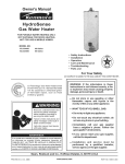
Owner's Manual
POWER
MISERTM 6
ULTRA LOW NOx
GAS WATER HEATER
FOR POTABLE WATER HEATING ONLY.
NOT SUITABLE FOR SPACE HEATING.
NOT FOR USE IN MOBILE HOMES.
MODEL NO.
153.330632
153.330642
30 Gallon
40 Gallon
153.330620
153.330652
40 Gallon (Short)
50 Gallon
• Safety Instructions
• Installation
• Operation
• Care and Maintenance
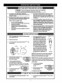
This water heater meets the new ANSI Z21.10.1
standard
that deals with the accidental
or
unintended
ignition of flammable
as those emitted by gasoline.
vapors,
• Troubleshooting
• Parts List
such
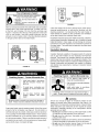
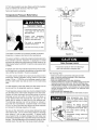
For Your Safety
AN ODORANT
Read and understand
inst[uction
manual and safety messages
before installing, operating or
servicing this water heater.
Failure to follow instructions
and
safety messages could result in
death or serious injury.
Instruction
with water
manual
heater.
must remain
tS ADDED TO THE GAS USED BY THIS WATER HEATER.
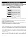
WARNING:
If the information
in these
instructions is not followed exactly, a fire
or explosion may result causing property
damage, personal injury or death.
--Do
not store or use gasoline or other
flammable
vapors and liquids in the
vicinity of this or any other appliance.
-- WHAT TO DO IF YOU SM ELL GAS:
• Do not try to light any appliance.
Si no puede leer o entender el ingles y necesita el manual de
instrucciones en espaSol, puede solicitarlo al 1-800-821-2017. NO
TRATE DE INSTALAR U OPERAR ESTE CALENTADOR DEAGUA
SI NO ENTIENDE LAS INSTRUCCIONES.
No hacer caso de esta
• Do not touch any electrical switch; do
not use any phone in your building.
• Immediately
call your gas supplier
from a neighbor's
phone. Follow the
gas supplier's instructions.
advertencia podria originar lesiones graves o mortales.
• If you cannot reach your gas supplier,
call the fire department.
--Installation
and
service
must
be
performed
by a qualified
installer,
service agency orthe gas supplier.
Sears,
PRINTED
IN THE U.S.A 0609
Roebuck
and Co., Hoffman
www,sears,com
Estates,
IL 60179
U.S.A
PART NO. 186190-002
Your safety and the safety of others is extremely important in the installation, use and servicing of this water heater.
Many safety-related messages and instructions have been provided in this manual and on your own water heater to warn you and
others of a potential hazard. Read and obey all safety messages and instructions throughout this manual. It is very important that
the meaning of each safety message is understood by you and others who install, use or service this water heater.
This is the safety alert symbol. It is used to alert you
to potential personal injury hazards. Obey all safety
messages that follow this symbol to avoid possible
injury or death.
DANGER indicates an imminently hazardous
situation which, if not avoided, will result in
death or injury.
WARNING indicates a potentially hazardous
situation which, if not avoided, could result
in death or injury.
CAUTION indicates a potentially hazardous
situation which, if not avoided, could result
in minor or moderate injury.
CAUTION used without the safety alert
symbol indicates a potentially hazardous
situation which, if not avoided, could result
in property damage.
All safety messages will generally tell you about the type of hazard, what can happen if you do not follow the safety message and
how to avoid the risk of injury.
The California Safe Drinking Water and Toxic Enforcement Act requires the Governor of California to publish a list of
substances known to the State of California to cause cancer, birth defects, or other reproductive harm, and requires
businesses to warn of potential exposure to such substances.
WARNING: This product contains a chemical known to the State of California to cause cancer, birth defects, or other
reproductive harm.
This appliance can cause low-level exposure to some of the substances included in the Act.
IMPORTANT DEFINITIONS
Qualified Installer: A qualified installer must have ability equivalent to a licensed tradesman in the fields of plumbing.
air supply, venting and gas supply, including a thorough understanding of the requirements of the National Fuel Gas
Code as it relates to the installation of gas fired water heaters. The qualified installer must also be familiar with the
design features and use of flammable vapor ignition resistant water heaters, and have a thorough understanding of this
instruction manual.
Service Agency: A service agency also must have ability equivalent to a licensed tradesman in the fields plumbing
air supply, venting and gas supply, including a thorough understanding of the requirements of the National Fuel Gas
Code as it relates to the installation of gas fired water heaters. The service agency must also have a thorough
understanding of the instruction manual, and be able to perform repairs strictly in accordance with the service guidelines
provided by the manufacturer.
Gas Supplier: The natural gas or propane utility or service who supplies gas for utilization by the gas burning
appliances within this application. The gas supplier typically has responsibility for the inspection and code approval of
gas piping up to and including the natural gas meter or propane storage tank of a building. Many gas suppliers also
offer service and inspection of appliances within the building.
© Sears, Roebuck and Co.
Read and understand instruction
Fire Hazard
manual and safety messages
before installing, operating or
servicing this water heater.
Failure to follow instructions and
safety messages could result in
For continued protection against
riskof fire:
• Do not install water heater on
carpeted floor.
death or serious injury.
Instruction manual must remain
with water heater.
• Do not operate water heater if
flood damaged.
Water temperature
over 125°F
(52°C) can cause severe burns
instantly resulting in severe injury
or death,
Explosion
• Overheated water can cause
watertank explosion.
Children, the elderly, and the
physically or mentally disabled
are at highest riskforscald
injury.
Feel water
showering.
before
bathing
Temperature
available.
limiting
valves
Hazard
• Properly sized temperature
and pressure relief valve must
be installed
in opening
provided.
or
are
Read instruction manual for safe
temperature setting
Breathing
Fire or Explosion
Hazard - Carbon
Monoxide
• Install vent system
codes.
Hazard
• Do not operate
• Do not store or use gasoline or other flammable
vapors and liquids in the vicinity of this or any other
appliance.
• Avoid all Lgnition sources if you smell LP gas.
• Do not expose water heater control to excessive gas
pressure.
• Use only gas shown on rating plate.
• Maintain required clearances to combustibles.
• Keep ignition sources away from faucets after
extended period of non-use.
JllmLI
Gas
in accordance
water
heater
with
if flood
damaged.
• High altitude orifice must be installed for
operation
above 2,000
feet (610 m),
• Do not operate if soot buildup.
• Do not obstruct water heater air intake
with insulating jacket,
• Do not place chemical
vapor
products near water heater,
• Gas and carbon monoxide
emitting
detectors
are available.
installing, using or sewicing
water heater.
Read instruction
manual before
Improper
•
•
•
•
•
Breathing carbon monoxide can cause brain damage or
death. Always read and understand instruction manual.
installation and use may result
in property damage.
Do not operate water heater if flood damaged.
Inspect and replace anode.
Install in location with drainage.
Fill tank with water before operation.
Be alert for thermal expansion.
Refer to instruction manual for installation and service.
SAFE INSTALLATION,
USE AND SERVICE ......................................................................................................................2
SAFETY PRECAUTIONS
..............................................................................................................................
3
TABLE OF CONTENTS .................................................................................................................................
4
CUSTOMER
RESPONSIBILITIES
......................................................................................................................................... 5
PRODUCT SPECIFICATIONS
................................................................................................................................................ 5
MATERIALS AND BASIC TOOLS NEEDED ....................................................................................................................... 6
Materials Needed .....................................................................................................................................................
6
Basic Tools ................................................................................................................................................................
6
TYPICAL INSTALLATION .......................................................................................................................................................... 7
INSTALLATION
INSTRUCTIONS
......................................................................................................................................8-17
Removing the Old Water Heater ...............................................................................................................................
8
Facts to Consider About the Location ..................................................................................................................
9-10
Insulation Blankets .................................................................................................................................................
10
Combustion Air and Ventilation Appliances in Unconfined Spaces ........................................................................
11
Combustion Air and Ventilation Appliancesin Confined Spaces ........................................................................
11-12
Water Piping ......................................................................................................................................................
12-13
T & P Valve and Pipe Insulation ........................................................................................................................
13-14
Temperature Pressure Relief Valve ...................................................................................................................
13-14
Filling the Water Heater ..........................................................................................................................................
15
Venting ...............................................................................................................................................................
15-16
Gas Piping .........................................................................................................................................................
16-17
Sediment Trap ........................................................................................................................................................
17
OPERATING
INSTRUCTIONS
......................................................................................................................................... 18-19
Lighting & Operating Label .....................................................................................................................................
18
Temperature Regulation .........................................................................................................................................
19
SERVICE AND ADJUSTMENT
........................................................................................................................................20-22
Tank (Sediment) Cleaning ......................................................................................................................................
20
Venting System Inspection .....................................................................................................................................
20
Burner Inspection ...................................................................................................................................................
20
Removing the Burner Door Assembly ....................................................................................................................
21
Ultra Low NOx Natural Gas Burner ........................................................................................................................
21
Replacing the Pilot Assembly .................................................................................................................................
21
Replacing the Thermocouple ..................................................................................................................................
22
External Inspection & Cleaning of the Flame Arrestor ............................................................................................
22
Cleaning the Combustion Chamber and Flame Arrestor ........................................................................................
22
Replacing the Burner Door Assembly .....................................................................................................................
23
Piezoelectric Igniter System ...................................................................................................................................
23
Testing the Igniter System ......................................................................................................................................
23
Removing and Replacing the Gas Control Valve/Thermostat ................................................................................
24
Housekeeping .........................................................................................................................................................
24
Anode Rod Inspection ............................................................................................................................................
24
Temperature-Pressure Relief Valve Operation .......................................................................................................
25
Draining ..................................................................................................................................................................
25
Drain Valve Washer Replacement ..........................................................................................................................
25
Service ....................................................................................................................................................................
25
TROUBLESHOOTING
GUIDE ........................................................................................................................................ 26-30
Start Up Conditions ...........................................................................................................................................
26-27
Thermal Expansion ...........................................................................................................................................
26
Strange Sounds ................................................................................................................................................
26
Draft Hood Operation ........................................................................................................................................
26
Condensation ....................................................................................................................................................
27
Smoke/Odor ......................................................................................................................................................
27
Operational Conditions ...........................................................................................................................................
27
Smelly Odor ......................................................................................................................................................
27
Air in Hot Water Faucets ...................................................................................................................................
27
High Temperature Shut-Off System ..................................................................................................................
27
Troubleshooting Items .......................................................................................................................................
28-30
PARTS ORDER LIST ................................................................................................................................................................31
WARRANTY .................................................................................................................................................................................32
Thank You for purchasing a Kenmore water heater. Properly
installed and maintained, it should give you years of trouble free
service. If you should decide that you want the new water heater
professionally installed by Sears, call 1-800-4-MY-HOME ®.They
will arrange for prompt, quality installation by Sears authorized
contractors.
Abbreviations
ENTIRE MANUAL BEFORE ATTEMPTING TO INSTALL OR
OPERATE THE WATER HEATER.
•
Found In This Instruction Manual:
CSA- Canadian Standards Association
ANSI- American National Standards Institute
•
NFPA- National Fire Protection Association
ASME - American Society of Mechanical Engineers
GAMA- Gas Appliance Manufacturers Association
This gas-fired water heater is design certified by CSA
INTERNATIONAL under American National Standard/CSA
Standard for Gas Water Heaters ANSI Z21.10.1 • CSA 4.1
(current edition).
Read the "Safety Precautions" section, page 3 of this manual
first and then the entire manual carefully. If you don't follow
the safety rules, the water heater wilt not operate properly. It
could cause DEATH, SERIOUS BODILY INJURY AND/OR
PROPERTY DAMAGE.
This manual contains instructions for the installation, operation,
and maintenance of the gas-fired water heater. It also contains
warnings through out the manual that you must read and be
aware of. All warnings and all instructions are essential to the
proper operation of the water heater and your safety. Since
we cannot put everything on the first few pages, READ THE
TANK
CAPACITY
MODEL
NUMBER
153.330632
153.330642
153.330620
153.330652
IN
30(114)
40 (151)
40 (151)
50 (189)
TYPE OF
GAS
NATU
NATU
NATU
NATU
RAL
RAL
RAL
RAL
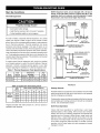
Examine the location to ensure the water heater complies
with the Facts to Consider About the Location section in this
manual.
•
For California installation this water heater must be braced,
anchored, or strapped to avoid falling or moving during an
earthquake. See instructions for correct installation procedures.
Instructions may be obtained from the California Office of the
State Architect, 1102 Q Street, Suite 5100, Sacramento, CA
95811. Instructions can also be downloaded to your computer
at WWW.dsa.dgs.ca.gov/Pubs.
•
Complies with 10 ng/J SCAQMD rule #1121 and districts
having equivalent NOx requirements.
RECOVERY
RATE GALS.
MINIMUM
VENT PIPE
DIAM ETER
PER HOUR @
90°F RISE
INCHES
INCHES
(Btu/hr)
30,000
40,000
36,000
40,000
31.0
41.0
39.0
41.0
INPUT
GALS (LTRS)
•
The installation must conform with these instructions and
the local code authority having jurisdiction.
In the absence
of local codes, installations shall comply with the current
edition of The National Fuel Gas Code ANSI Z223.1/NFPA
54. This publication is available from the Canadian Standards
Association,
8501 East Pleasant Valley Rd, Cleveland
Ohio 44131, or The National Fire Protection Association, 1
Batterymarch Park, Quincy, MA 02269.
If after reading this manual you have any questions or do
not understand any portion of the instructions, call the Sears
Service Center.
Carefully plan the place where you are going to put the
water heater. Correct combustion, vent action, and vent
pipe installation
are very important in preventing death
from possible carbon monoxide poisoning and fires. See
figure 1.
RATE
(mm)
3"
3"
3"
3"
(76)
(76)
(76)
(76)
OR
OR
OR
OR
4"
4"
4"
4"
DIMENSIONS
(mm)
(102)
(102)
(102)
(102)
16-3/8"(415.9)
18" (457)
22" (559)
20" (508)
INCHES (mm)
HEIGHT TO
JACKET TOP
56 3!8" (1,432)
58 3!8" (1,483)
49" (1,245)
57 3!8" (1,457)
IN
Materials
Needed
To simplify the installation, Sears has available the installation parts shown below. You may or may not need all of these materials,
depending on your type of installation.
METAL DRAIN PANS AVAILABLE
EXPANSION TANKS FOR
THERMAL EXPANSION
CONDITIONS AVAILABLE
IN 2 GALLONS
(7.6 LITERS) AND
5 GALLONS (18.9 LITERS)
CAPACITY THROUGH
LOCAL SEARS STORE
OR SERVICE CENTER.
IN 20" (508 mm) DIAMETER
FOR WATER HEATERS HAVING
A DIAMETER 18" (457 mm) OR
LESS, 24" (610mm) DIAMETER
FOR WATER HEATERS HAVING
A DIAMETER 22" (559 mm) OR
LESS AND AVAILABLE IN 28"
WATER HEATER INSTALLATION KIT WITH
FLEXIBLE CONNECTORS FOR 3/4"
(711 mm) DIAMETER FOR WATER
HEATERS HAVING A DIAMETER
26" (660 mm) OR LESS.
(19.05 ram) OR 1/2" (12.7 mm) THREADED OR
COPPER PLUMBING AND FLEXIBLE WATER
HEATER GAS CONNECTOR WITH FITTINGS.
Basic Tools
Additional
You may or may not need all these tools, depending on your
type of installation. These tools can be purchased at your local
Sears Store.
• Pipe Wrenches (2) 14" (356 mm)
• Screwdriver
•
•
•
•
Tools Needed
When Sweat Soldering
•
•
•
•
Tubing Cutters or Hacksaw
Propane Tank
Soft Solder
Solder Flux
1
• Emery Cloth
• Wire Brushes
Tin Snips
6' (1.82 m) Tape or Folding Ruler
Garden Hose
Drill
• Pipe Dope or Teflon Tape
DRILL
TUBING
SLOT-HEAD
\
CUTTER
PROPANE
TORCH
SCREWDRIVER
TIN SNIPS
PHILLIPS SCREWDRIVER
HACKSAW
ROLL OF
EMERY CLOTH
PIPE DOPE
ROLL OF TEFLON
TAPE (USE ONLY ON
WATER CONNECTIONS)
(SQUEEZE TUBE)
USE FOR WATER AND GAS
CONNECTIONS
G
3/4" (19 mm) WIRE BRUSH
GARDEN
HOSE
6 FOOT TAPE
PIPE WRENCH
1/2" (13 mm)WIRE
BRUSH
ROLL OF LEAD-FREE
SOFT SOLDER
SOLDER
FLUX
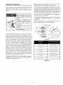
GET TO KNOW YOUR
A
B
C
D
E
F
G
H
I
Vent Pipe
Drafthood
Anode
Hot Water Outlet
Outlet
Flexible Water Connections
Gas Supply
Manual Gas Shut-off Valve
Ground Joint Union
* INSTALL
WITH
J
K
L
M
N
O
P
Q
R
WATER HEATER
- GAS MODELS
S
T
U
V
W
X
Y
Drip Leg (Sediment Trap)
Inner Door
Outer door
Union
Inlet Water Shut-off Valve
Cold Water Inlet
Inlet Dip Tube
Temperature-Pressure
Relief Valve
Rating Plate
Flue Baffle
Gas Control Valve/Thermostat
Drain Valve
Pilot and Main Burner
Flue
Metal Drain Pan
Piezo Igniter
IN ACCORDANCE
LOCAL
CODES.
(T) GAS CONTROL VALVE/
THERMOSTAT
* DRIP LEGAS REQUIRED
BY LOCAL CODES.
GAS CONTROL
KNOB
f
TO VENT TERMINATION
ON ROOF
INSTALL
TANK
THERMAL
OR
HEATER
CLOSED
DEVICE
EXPANSION
IF WATER
IS INSTALLED
WATER
IN A
SYSTEM
o
WATER TEMPERATURE
(ADJUSTING DIAL)
M
B
F
VACUUM RELIEF
VALVE
*INSTALL
PER
LOCAL CODES
"OFF
POSITION
PILOT ....
POSITION
ON"
POSITION
E
TOP VIEW
(V) PILOT & MAIN BURNER
DISCHARGE
J
PIPE
MAIN BURNER
(Do not cap or plug)
PILOT TUBING
BURNER
TUBE
G
H
W
I
_
6" MAXIMUM
AIR GAP
THERMOCOUPLE
IGNITER ROD
/
X
/'
K
* ALL PIPING MATERIALS
TO BE
SUPPLIED
BY CUSTOMERS.
FIGURE
7
1.
Removing
the Old Water Heater
Q
®
Attach a hose to the water heater
drain valve and put the other end in
a floor drain or outdoors. Open the
water heater drain valve. Open a
nearby hot water faucet which wilt
relieve pressure in the water heater
and speed draining.
The water
passing out of the drain valve may
be extremely hot. To avoid being
scalded, make sure all connections
are tight and that the water flow is
directed away from any person, see
Figures 2 and 5.
FIGURE
5.
Disconnect the vent pipe from the draft hood where it connects
to the water heater. In most installations the vent pipe can
be lifted off after any screw or other attached devices are
removed. Dispose of the draft hood. The new water heater
has a draft hood which must be used for proper operation.
G
If you have copper piping to the water heater, the two copper
water pipes can be cut with a hacksaw approximately four
inches away from where they connect to the water heater,
see Figure 6. This wilt avoid cutting off pipes too short.
Additional cuts can be made later if necessary. Disconnect the
temperature-pressure
relief valve drain line. When the water
heater is drained, disconnect the hose from the drain valve.
Close the drain valve. The water heater is now completely
disconnected and ready to be removed.
FIGURE 2.
QTurn
"OFF" the gas supply to the
water heater.
If the main gas line shutoff valve
serving all gas appliances is used,
also shut "OFF" the gas at each
appliance. Leave all gas appliances
shut "OFF" until the water heater
installation
is completed,
see
Figures 2 and 3.
Q
Turn "OFF" the water supply to
the water heater at the water shut
off valve or water meter. Some
installations require that the water
be turned off to the entire house,
see Figures 2 and 4.
FIGURE
3.
FIGURE 4.
Check again to make sure the gas supply is "OFF" to the
water heater. Then disconnect the gas supply connection from
the gas control valve.
• Burn hazard
• Hotwater discharge.
• Keep hands clear of drain
valve discharge.
FIGURE 6.
If you have galvanized pipes to the water heater, loosen
the two galvanized pipes with a pipe wrench at the union in
each line. Also disconnect the piping remaining to the water
heater, see Figure 7. These pieces should be saved since
they may be needed when reconnecting the new water heater.
Disconnect the temperature-pressure
relief valve drain line.
When the water heater is drained, disconnect the hose from
the drain valve. Close the drain valve. The water heater is now
completely disconnected and ready to be removed. Mineral
buildup or sediment may have accumulated in the old water
heater. This causes the water heater to be much heavier than
normal and this residue, if spilled out, could cause staining.
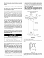
Facts to Consider
the Location
About
•
Carefully choose an indoor location for the new water heater.
The placement is a very important consideration for the safety
of the occupants in the building and for the most economical
use of the appliance. This water heater is not for use in
manufactured (mobile) homes or outdoor installation.
Whether replacing an old water heater or putting the water
heater in a new location, the following critical points must be
observed:
•
Select a location indoors as close as practical to the gas
vent or chimney to which the water heater vent is going to be
connected, and as centralized with the water piping system
as possible.
•
Selected location must provide adequate clearances
servicing and proper operation of the water heater.
for
Devices that wilt turn off the gas supply to a gas water heater
while at the same time shutting off its water supply.
Fire or Explosion
• Do not store or use gasoline or other flammable
vapors and liquids in the vicinity of this or any other
appliance.
• Avoid all ignition sources if you smell LP gas.
• Do not expose water heater control to excessive gas
pressure.
• Use only gasshewn on ratingplate.
• Maintain required clearances to combustibles.
• Keep ignition sources away frcrn faucets after
_, extended period of non-use.
,dlnLj
d_j_,
_i_J
Property
Damage Hazard
• AH water heaters eventually leak
• Do n,otinstall without adequate drainage.
Installation of the water heater must be accomplished in such a
manner that if the tank or any connections should leak, the flow
wilt not cause damage to the structure. For this reason, it is not
advisable to install the water heater in an attic or upper floor. When
such locations cannot be avoided, a suitable metal drain pan should
be installed under the water heater. Metal drain pans are available
at your local Sears or hardware store. Such a drain pan must have
a minimum length and width of at least 2 inches (51 mm) greater
than the water heater dimensions and must be piped to an adequate
drain. The pan must not restrict combustion air flow.
Water heater life depends upon water quality, water pressure
and the environment in which the water heater is installed. Water
heaters are sometimes installed in locations where leakage may
result in property damage, even with the use of a metal drain
pan piped to a drain. Unanticipated damage can be reduced
or prevented by a leak detector or water shut-off device used
in conjunction with a piped metal drain pan. These devices are
available from some plumbing supply wholesalers and retailers,
and detect and react to leakage in various ways:
•
Sensors mounted in the metal drain pan that trigger an alarm
or turn off the incoming water to the water heater when leakage
is detected.
•
Sensors mounted in the metal drain pan that turn off the water
supply to the entire home when water is detected in the metal
drain pan.
•
Water supply shut-off devices that activate based on the water
pressure differential between the cold water and hot water
pipes connected to the water heater.
Hazard
Read instruction n_anual before
installing, using or servicing
water heater.
INSTALLATIONS IN AREAS WHERE FLAMMABLE LIQUIDS
(VAPORS) ARE LIKELY TO BE PRESENT OR STORED
(GARAGES, STORAGEAND UTILITYAREAS, ETC.): Flammable
liquids (such as gasoline, solvents, propane [LP or butane, etc.]
and other substances such as adhesives, etc.) emit flammable
vapors which can be ignited by a gas water heater's pilot light or
main burner. The resulting flashback and fire can cause death
or serious burns to anyone in the area. Even though this water
heater is a flammable vapor ignition resistant water heater and
is designed to reduce the chances of flammable vapors being
ignited, gasoline and other flammable substances should never
be stored or used in the same vicinity or area containing a gas
water heater or other open flame or spark producing appliance.
Also, the water heater must be located and/or protected so it is
not subject to physical damage by a moving vehicle.
Fire Hazard
For continued protection against
riskof fire:
• Do not install water heater on
carpeted floor.
• Do not operate water heater if
flood damaged.
This water heater must not be installed directly on carpeting.
Carpeting must be protected by metal or wood panel beneath
the appliance extending beyond the full width and depth of the
appliance by at least 3 inches (76.2mm) in any direction, or if
the appliance is installed in an alcove or closet, the entire floor
must be covered by the panel. Failure to heed this warning may
result in a fire hazard.
12" MAX. (30 cm)
Fire or Explosion
Hazard
3" MIN.
76,2 mm
AIR DUCT
using or servicing water heater.
Read
• Improper use may result in fire or
explosion.
instruction manual before installing,
• Maintain required clearances to
combustibles.
FRONT
Propellants of aerosol sprays and volatile compounds, (cleaners,
chlorine based chemicals, refrigerants, etc.) in addition to being
highly flammable in many cases, wilt also change to corrosive
hydrochloric acid when exposed to the combustion products of
the water heater. The results can be hazardous, and also cause
product failure.
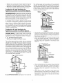
Insulation
Blankets
0" MIN.
Insulation blankets available to the general public for external
use on gas water heaters are not necessary with Kenmore
products. The purpose of an insulation blanket is to reduce the
standby heat toss encountered with storage tank heaters. Your
Kenmore water heater meets or exceeds the National Appliance
Energy Conservation Act standards with respect to insulation
and standby loss requirements, making an insulation blanket
unnecessary.
4" IV]IN.
(104 ram)
0" MIN.
FIGURE
8.
Breathing
Breathing
Hazard - Carbon Monoxide
place chemical
products
near
Monoxide
Gas
",_°'..'.;:
intake with insulating blanket.
obstruct monoxide
water heater
air
"::':;_'::_ •• Do
Gas not
and carbon
detectors
__!il
To avoid injury, combustion and
ventilation air must be taken from
outdoors.
Do not
emitting
heater.
Hazard - Carbon
Gas
Install water heater in accordance
with the instruction manual and
NFPA 54.
•
9.
If this water heater wilt be used in beauty shops, barber shops,
cleaning establishments,
or self-service laundries with dry
cleaning equipment, it is imperative that the water heater or
water heaters be installed so that combustion and ventilation
air be taken directly from outdoors (direct vent).
TOP VIEW
OF CLOSET
WITH DOOR
0" MIN.
_"
FIGURE
Minimum clearances between the water heater and combustible
surfaces are 0 inch at the sides and rear, 4 inches (102 mm)
at the front, and 6 inches (153 mm) from the vent pipe, see
Figure 8. Clearance from the top of the jacket is 8 inches (203
mm) on most models. Note that a lesser dimension may be
allowed on some models, refer to the label attached adjacent
to the gas control valve on the water heater.
TOP VIEW
OF CLOSET
WITHOUT DOOR
VIEW
OF DOOR
__
_.i'_
• are
Install
ava,table.
water heater in accordance
with the instruction manual.
I
Breathing carbon monoxide can cause brain damage or
death. Always read and understand instruction manual.
vapor
water
'_
Breathing carbon monoxide can cause brain damage or
death. Always read and understand instruction manual.
WARNING
Should you choose to apply an insulation blanket to this
heater, you should follow these instructions (See Figure 1 for
identification of components mentioned below). Failure to follow
these instructions can restrict the air flow required for proper
combustion, potentially resulting in fire, asphyxiation, serious
personal injury or death.
• Do not apply insulation to the top of the water heater, as this
wilt interfere with safe operation of the draft hood.
A gas water heater cannot operate properly without the correct
amount of air for combustion, see Figure 9. Do not install in a
confined area such as a closet, unless you provide air as shown
in the Locating The New Water Heater section. Never obstruct
the flow of ventilation air. If you have any doubts or questions at
all, call your gas supplier. Failure to provide the proper amount of
combustion air can result in a fire or explosion and cause death,
serious bodily injury, or property damage.
•
Do not cover the outer door, thermostat
pressure relief valve.
•
Do not allow insulation to come within 2" (50.8 mm) of the floor
to prevent blockage of combustion air flow to the burner.
Do not cover the instruction manual. Keep it on the side of
the water heater or nearby for future reference.
•
10
or temperature
&
• Doobtainnewwarning
andinstruction
labels
fromSears
for
placement
ontheblanket
directly
overtheexisting
labels.
• Doinspect
theinsulation
blanket
frequently
tomakecertain
itdoesnotsag,thereby
obstructing
combustion
airflow.
Combustion
Air and Ventilation
Appliances
Located
for
in Unconfined
The confined space shall be provided with two permanent
openings, one commencing within 12 inches (30 cm) of the top
and one commencing within 12 inches (30 cm)from the bottom
of the enclosure. The openings shall communicate directly, or
by ducts, with the outdoors or spaces (crawl or attic) that freely
communicate with the outdoors.
Spaces
CHIMNEY
OR
GAS VENT
VENTILATION
OUTLETAIR
In unconfined spaces in buildings, infiltration may be adequate
to provide air for combustion, ventilation and dilution of flue
gases. However, in buildings of tight construction (for example,
weather stripping, heavily insulated, caulked, vapor barrier,
etc.), additional air may need to be provided using the methods
described in Combustion Air and Ventilation for Appliances
Located in Confined Spaces.
Combustion
Air and Ventilation
Appliances
Located
WATER HEATER
FURNACE
INLET MR DUCT
for
in Confined
LOUVERS
END OF ATTIC)
UNCONFINED SPACE is space whose volume is not tess than
50 cubic feet per 1,000 Btu per hour (4.8 m3 per kW) of the
aggregate input rating of all appliances installed in that space.
Rooms communicating
directly with the space in which the
appliances are installed, through openings not furnished with
doors, are considered a part of the unconfined space.
ALT. INLETAIR
Spaces
VENTILATION
FIGURE
LOUVERS
11.
When directly communicating with the outdoors, each opening
shall have a minimum free area of 1 square inch per 4,000 Btu
per hour (5.5 cm2/kW) of total input rating of all equipment in
the enclosure. See Figure 11.
When communicating
with the outdoors through vertical
ducts, each opening shall have a minimum free area of
1 square inch per 4,000 BTU per hour (5.5 cm2/kW) of
total input rating of all equipment in the enclosure. See
Figure 12.
CONFINED SPACE is a space whose volume is tess than
50 cubic feet per 1,000 Btu per hour (4.8 m3 per kW) of the
aggregate input rating of all appliances installed in that space.
A. ALL AIR FROM INSIDE BUILDINGS:
(See Figure 9 on page 10 and Figure 10 below)
The confined space shall be provided with two permanent
openings communicating directly with an additional room(s) of
sufficient volume so that the combined volume of all spaces
meets the criteria for an unconfined space. The total input of all
gas utilization equipment installed in the combined space shall
be considered in making this determination. Each opening shall
have a minimum free area of one square inch per 1,000 Btu per
hour (22 cm2/kW) of the total input rating of all gas utilization
equipment in the confined space, but not tess than 100 square
inches (645 cm2). One opening shall commence within 12 inches
(30 cm) of the top and one commencing within 12 inches (30
cm) of the bottom of the enclosures.
VENTILATION
LOUVERS
OF ATTIC)
WATER
HEATER
• FURNACE
CHIMNEY OR GAS VENT
INLET AIR DUCT
(ENDS
_
171
_:_, ' r'
,
,
,
L_!
[
R
!
l
F
I_!
[
t
[--!
1
IJ
!
J
i
[ !
I-_1
I"
[_!
_
1
1
ILIZr
FIGURE
10.
B. ALL AIR FROM OUTDOORS: (See Figures 9, 11,12,13 and 13A)
11
12.
•
When communicating with the outdoors through horizontal
ducts, each opening shall have a minimum free area of
1 square inch per 2,000 BTU per hour (11 cm2/kW) of
total input rating of all equipment in the enclosure. See
Figure 13.
•
When ducts are used, they shall be of the same crosssectional area as the free area of the openings to which
they connect. The minimum short side dimension
of
rectangular
air ducts shall not be less than 3 inches
(76.2 mm). See Figure 13.
OPENINGS
1
ABOVEFLOOR)
•
1
FIGURE
FURNA
1' OR 30 cm
GAS
Water Piping
VENT
Water temperature
over 125°F
(52°C) can cause severe burns
instantly resulting in severe injury
or death.
,)
physically or mentally disabled
a re at highest elderly,
riskfor scald
Children,
and injury.
the
_._
Feel
_.
Temperature limiting valves are
available.
Read instruction manual for safe
tern perature setting,
_)(_
water
before
bathing
or
INLET AIR DUCT
FIGURE
.
13.
Alternatively a single permanent opening may be used when
communicating directly with the outdoors, or with spaces that
freely communicate with the outdoors. The opening shall
have a minimum free area of 1 square inch per 3,000 BTU
per hour (8.3 cm2/kW) of total input rating of all equipment in
the enclosure. See Figure 13A.
HOTTER WATER CAN SCALD:
Water heaters are intended to produce hot water.
Water
heated to a temperature which will satisfy space heating,
clothes washing, dish washing, cleaning and other sanitizing
needs can scald and permanently injure you upon contact.
Some people are more likely to be permanently injured by
hot water than others. These include the elderly, children, the
infirm, or physically/mentally
handicapped. If anyone using hot
water in your home fits into one of these groups or if there is a
local code or state law requiring a certain temperature water
at the hot water tap, then you must take special precautions.
In addition to using the lowest possible temperature setting
that satisfies your hot water needs, a means such as a *mixing
valve should be used at the hot water taps used by these
people or at the water heater. Mixing valves are available at
plumbing supply or hardware stores. See Figure 14. Valves
for reducing point of use temperature by mixing cold and hot
water are also available. Follow manufacturer's
instructions
OR
GAS VENT
OPENING
LOCATION
for installation of the valves.
Before changing
setting on the thermostat, read the Temperature
section in this manual.
COLD
HOoTuWATER
FIGURE
the factory
Regulation
WATER
13A.
Louvers and Grilles: In calculating free area, consideration
shall be given to the blocking effect of louvers, grilles or
screens protecting openings.
Screens used shall not be
smalter than 1/4 inch (6.4 mm) mesh. If the free area through
a design of louver or grille is known, it should be used in
calculating the size opening required to provide the free area
specified. If the design and free area is not known, it may be
assumed that wood louvers wilt be 20-25 percent free area
and metal louvers and grilles wilt have 60-75 percent free
area. Louvers and grilles shall be fixed in the open position
or interlocked with the equipment so that they are opened
automatically during equipment operation.
TLET _
TEMPERED
_]]__J
WATEROUTLET_.T_L.[_,_
_
+
+*NIXING
VALVE
HOT WATER
OUTLET ON
WATER HEATER
TO COLD WATER
INLET ON
WATER HEATER
FIGURE 14.
Special Conditions Created by Mechanical Exhausting or
Fireplaces: operation of exhaust fans, ventilation systems,
clothes dryers or fireplaces may create conditions requiring
special attention to avoid unsatisfactory operation of installed
gas utilization equipment.
Toxic
Chemical
Hazard
• Do not connect to non-potable water system.
12
This water heater shall not be connected to any heating
systems or component(s) used with a non-potable water heating
appliance.
Look at the top of the water heater. The cold water inlet is
marked "COLD". Put two or three turns of Teflon tape around
the threaded end of the threaded-to-sweat
coupling and
around both ends of the 3/4" NPT threaded nipple. Using
flexible connectors, connect the cold water pipe to the cold
water inlet of the water heater.
All piping components connected to this unit for space heating
applications shall be suitable for use with potable water.
NOTE: This water heater is super insulated to minimize
heat loss from the tank. Further reduction in heat loss
can be accomplished by insulating the hot water lines
from the water heater.
Toxic chemicals, such as those used for boiler treatment shall
not be introduced into this system.
Water supply systems may, because of such events as high line
pressure, frequent cut-offs or the effects of water hammer, have
installed devices such as pressure reducing valves, check valves,
back flow preventers, etc. to control these types of problems.
When these devices are not equipped with an internal by-pass,
and no other measures are taken, the devices cause the water
system to be closed. As water is heated, it expands (thermal
expansion) and closed systems do not allow for the expansion
of heated water.
INSTALLATION
COMPLETED
INSTALLATION
USING
KIT
FLEXIBLE
WATER
CONNECTORS
SHUTOFF
VALVE
HOT WATER
_
OUTLET
THREADED
SWEAT
TO
THREADED
COUPLING
INLET
TO
SWEAT COUPLING
3/4"THREADEDCOUPLING
The water within the water heater tank expands as it is heated
and increases the pressure of the water system. If the relieving
point of the water heater's temperature-pressure
relief valve
is reached, the valve will relieve the excess pressure.
The
temperature-pressure
relief valve is not intended for the
constant relief of thermal expansion. This is an unacceptable
condition and must be corrected. It is recommended that any
devices installed which could create a closed system have a
by-pass and/or the system have an expansion tank to relieve the
pressure built by thermal expansion in the water system. Refer
to the Thermal Expansion section under Troubleshooting Guide
or contact local plumbing authority or local Sears Service Center
on how to control this situation.
COLD WATER
_
3/4"THREADED
COUPLING
DRAFTHOOD
TEMPERATUREPRESSURE
RELIEF VALVE
NOTE: To protect against untimely corrosion of hot and cold
water fittings, it is strongly recommended that di-electric
unions or couplings be installed on this water heater when
connected to copper pipe.
(Do not cap or plug)
6" MAXIMUM
AIR GAP
Property
Damage
FLOOR DRAIN
Hazard
• Avoid water heater damage.
• Install thermal expansion tank if necessary.
T & P Valve and Pipe Insulation
• Do not apply heat to cold water inlet.
• Contact qualified installer or Sears Service Center.
Remove insulation for T & P valve and pipe connections
carton.
from
PIPE
INSULATION
Figure 15 shows the typical attachment of the water piping to
the water heater. The water heater is equipped with 314" NPT
water connections.
ULTO
NOTE: If using copper tubing, solder tubing to an adapter
before attaching
the adapter to the cold water inlet
connection. Do not solder the cold water supply line directly
to the cold water inlet. It will harm the dip tube and damage
the tank.
•
FLUE PIPE
Look at the top cover of the water heater. The water outlet is
marked "HOT". Put two or three turns of Teflon tape around the
threaded end of the threaded-to-sweat coupling and around
both ends of the 3/4" NPT threaded nipple. Using flexible
connectors, connect the hot water pipe to the hot water outlet
on the water heater.
FIGURE 15A.
Fit pipe insulation over the incoming cold water line and the hot
water line. Make sure that the insulation is against the top cover
of the heater.
TEFLON® is a registered trademark of E.I. Du Pont De Nemours and Company.
13
Fit T & P valve insulation over valve. Make sure that the insulation
does not interfere with the lever of the T & P valve.
HOTW TT R
CO W#TER
Secure all insulation using tape.
SHUTOFF
Temperature-Pressure
Relief Valve
HOT
_
COLD
DRAFT
H
\
TEMPERATURE
- PRESSURE
RELIEF
Explosion
(OPTIONAL
Hazard
VALVE
VALVE
TOP
NOT
T&P
RELIEF
SHOWN)
• Temperature-pressure
relief valve
must comply with ANSI Z21.22
and ASME code.
_DISCHARGE
PIPE
(Do not cap or plug)
• Properly
sized
temperaturepressure relief valve must be
installed in opening provided.
• Can result in overheating
excessive tank pressure.
and
i
/
DRAIN
VALVE
• Can cause serious injury or death.
L
I 6" MAXIMUM
AIR
FLOOR
This heater is provided with a properly certified combination
temperature - pressure relief valve by the manufacturer.
FIGURE
The valve is certified by a nationally recognized testing laboratory
that maintains periodic inspection of production of listed
equipment as meeting the requirements for Relief Valves for Hot
Water Supply Systems, ANSI Z21.22 and the code requirements
of ASME.
GAP
DRAIN
16.
Water Damage
Hazard
- Temperature-pressure relief valve discharge
pipe must terminate at adequate drain.
If replaced, the valve must meet the requirements of local codes,
but not less than a combination temperature and pressure relief
valve certified as indicated in the above paragraph.
The Discharge Pipe:
• Shall not be smaller in size than the outlet pipe size of the
valve, or have any reducing couplings or other restrictions.
• Shall not be plugged or blocked.
• Shall be of material listed for hot water distribution.
• Shall be installed so as to allow complete drainage of both the
temperature-pressure
relief valve, and the discharge pipe.
• Shall terminate a maximum of six inches above a floor drain
or external to the building. In cold climates, it is recommended
that the discharge pipe be terminated at an adequate drain
inside the building.
• Shall terminate at an adequate drain.
• Shall not have any valve between the relief valve and tank.
The valve must be marked with a maximum set pressure not to
exceed the marked hydrostatic working pressure of the water
heater (150 psi = 1,035kPa) and a discharge capacity not tess
than the water heater input rate as shown on the model rating
plate.
For safe operation of the water heater, the relief valve must not
be removed from its designated opening nor plugged.
The temperature-pressure
relief valve must be installed directly
into the fitting of the water heater designed for the relief valve.
Position the valve downward and provide tubing so that any
discharge wilt exit only within 6 inches (153 mm) above, or
at any distance below the structural floor, see Figure 16. Be
certain that no contact is made with any live electrical part.
The discharge opening must not be blocked or reduced in
size under any circumstances.
Excessive length, over 30 feet
(9.14 m), or use of more than four elbows can cause restriction
and reduce the discharge capacity of the valve.
w7:1[el=1
Water temperature over 125°F
(52°C) can cause severe burns
instantly resulting in severe injury
ordeath.
Children, the elderly, and the
physically or mentally disabled
are at highest riskforscald
injury.
No valve or other obstruction is to be placed between the relief
valve and the tank. Do not connect tubing directly to discharge
drain unless a 6 inch air gap is provided. To prevent bodily
injury, hazard to life, or property damage, the relief valve must
be allowed to discharge water in quantities should circumstances
demand. Ifthe discharge pipe is not connected to a drain or other
suitable means, the water flow may cause property damage.
Feel water
showering.
before
bathing
or
Temperature
available.
limiting
valves
are
Read instruction manual for safe
temperature setting
14
The temperature-pressure relief valve must be manually operated
at least once a year. Caution should be taken to ensure that
(1) no one is in front of or around the outlet of the temperaturepressure relief valve discharge line, and (2) the water manually
discharged wilt not cause any bodily injury or property damage
because the water may be extremely hot.
ANSI Z21.68 (ANSI Z21.66 & 67, respectively, cover electrically
and mechanically actuated vent dampers). Before installation
of any vent damper, consult your local Sears Service Center or
the local gas supplier for further information.
If after manually operating the valve, it fails to completely reset
and continues to release water, immediately close the cold water
inlet to the water heater, follow the draining instructions, and
replace the temperature-pressure
relief valve with a new one.
Breathing
Damage
Hazard
• Avoid water heater damage.
• Fill tank with water before operating.
Gas
Breathing carbon monoxide can cause brain damage or
death. Always read and understand instruction manual.
Never use this water heater unless it is completely full of water.
To prevent damage to the tank, the tank must be filled with water.
Water must flow from the hot water faucet before turning "ON"
gas to the water heater.
To insure proper venting of this gas-fired water heater, the correct
vent pipe diameter must be utilized. Any additions or deletions
of other gas appliances on a common vent with this water
heater may adversely affect the operation of the water heater.
Consult your gas supplier if any such changes are planned.
For replacement heater installations where pre-existing venting
is used, the venting must be inspected for obstructions and if
deterioration is present, it must be replaced.
To fill the water heater with water:
Close the water heater drain valve by inserting a flat head
screwdriver in the slot on the stem and turn to the right
(clockwise). The drain valve is on the lower front of the water
heater.
•
Monoxide
• Vent dampers must be certified
in accordance with ANSI Z21.68.
• Vent damper must permit proper
drafting of water heater.
• Install properlysizedventing,
• Do not install without venting
outdoors.
• Do not installwithout drafthood
• If common
vented
install
in
accordance with NFPA 54.
• Be alert for obstructed or deteriorated vent system
to avoid
serious injury or death.
Filling the Water Heater
Property
Hazard - Carbon
Open the cold water supply valve to the water heater.
NOTE: The cold water supply valve must be left open
when the water heater is in use.
For proper venting in certain installations, a larger diameter vent
pipe may be necessary. Consult your local Sears Service Center
or gas supplier to aid you in determining the proper venting for
your water heater from the vent tables in the current edition of
the National Fuel Gas Code ANSI Z223.1/NFPA 54.
To insure complete filling of the tank, allow air to exit by
opening the nearest hot water faucet. Allow water to run until
a constant flow is obtained. This will let air out of the water
Periodically check the venting system for signs of obstruction or
deterioration and replace if needed.
heater and the piping.
The combustion
obstructed.
Check all water piping and connections for leaks. Repair as
needed.
and ventilation
air flow
must
not be
The water heater with draft hood installed must be connected
to a chimney or listed vent pipe system, which terminates to the
outdoors. Never operate the water heater unless it is vented
to the outdoors and has adequate air supply to avoid risks of
improper operation, explosion or asphyxiation.
Venting
VENT DAMPERS - Any vent damper, whether it is operated
thermally or otherwise must be removed if its use inhibits proper
drafting of the water heater.
•
For proper draft hood attachment,
be angled slightly inward.
Thermally Operated Vent Dampers: Gas-fired water heaters
having thermal efficiency in excess of 80% may produce a
relatively tow flue gas temperature.
Such temperatures may
not be high enough to properly open thermally operated vent
dampers. This would cause spillage of the flue gases and may
cause carbon monoxide poisoning.
•
Place the draft hood legs in the receiving holes on the top
of the water heater. The legs wilt snap in the holes to give a
tight fit. Secure the legs to top with sheet metal screws. See
Figure 17.
•
Place the vent pipe over the draft hood. With the vent pipe
in position, drill a small hole through both the vent pipe and
draft hood. Secure them together with a sheet metal screw.
Vent dampers must bear evidence of certification as complying
with the current edition of the American National Standard
Obstructed or deteriorated
health risk or asphyxiation.
15
the draft hood legs may
vent systems may present serious
SHEET
METAL SCR&WS
tNSIALL THE ORAFT
THE FOUR SCREWS
Be sure vent pipe is properly connected to prevent escape of
dangerous flue gases which could cause deadly asphyxiation.
(_O_t _e/_4d_}
Chemical vapor corrosion of the flue and vent system may occur
if air for combustion contains certain chemical vapors. Spray can
propellants, cleaning solvents, refrigerator and air conditioner
refrigerants, swimming pool chemicals, calcium and sodium
chloride, waxes, bleach and process chemicals are typical
compounds which are potentially corrosive.
HOOD WITH
PROVIDED.
FIGURE 17.
Gas Piping
The vent pipe from the water heater must be no tess than the
diameter of the draft hood outlet on the water heater and must
slope upward at least 1/4 inch per linear foot (21 mm per meter).
See Figure 18.
Fire and Explosion
TO
t
Excessive pressure to gas
control valve can cause serious
injury or death,
Turn off gas
installation.
FIGURE
18.
Contact qualified
service agency.
All vent gases must be completely vented to the outdoors of the
structure (dwelling). Install only the draft hood provided with the
new water heater and no other draft hood.
Vent pipes must be secured
screws.
Hazard
Do not use water heater with
any gas other than the gas
shown on the rating plate.
CHIMNEY
lines during
installer
or
Make sure the gas supplied is the same type listed on the
model rating plate. The inlet gas pressure must not exceed
14 inch water column (3.5kPa) for natural and propane gas (L.E)
gas. The minimum inlet gas pressure listed on the rating plate
is for the purpose of input adjustment. If the gas control valve
is subjected to pressures exceeding 1/2 pound per square inch
(3.5kPa), the damage to the gas control valve could result in a
fire or explosion from leaking gas.
at each joint with sheet metal
There must be a minimum of 6 inches (153 mm) clearance
between single wall vent pipe and any combustible material.
Fill and seal any clearance between single wall vent pipe
and combustible material with mortar mix, cement, or other
noncombustible substance.
For other than single walt, follow
vent pipe manufacturer's clearance specifications. To insure a
tight fit of the vent pipe in a brick chimney, seal around the vent
pipe with mortar mix cement.
If the main gas line shutoffserving all gas appliances is used, also
turn "OFF" the gas at each appliance. Leave all gas appliances
shut "OFF" until the water heater installation is complete.
A gas line of sufficient size must be run to the water heater.
Consult the current edition of National Fuel Gas Code ANSI
Z223.1/NFPA
54 and your gas supplier concerning pipe size.
There must be:
Flue gases may escape if vent
pipe is not connected.
Do not store corrosive chemicals
in vicinity of water heater_
Chemical corrosion of flue and
vent system can cause serious
injury or death.
Contact a qualified installer or
service agency.
•
A readily accessible manual shut off valve in the gas supply
line serving the water heater.
•
A drip leg (sediment trap) ahead of the gas control valve to
help prevent dirt and foreign materials from entering the gas
control valve.
•
Aflexible gas connector or a ground joint union between the
shut off valve and control valve to permit servicing of the
unit.
Breathing carbon monoxide can cause brain damage
or death. Always read and understand instruction manual.
Be sure to check all the gas piping for leaks before lighting the
water heater. Use a soapy water solution, not a match or open
flame. Rinse off soapy solution and wipe dry.
Failure to have required clearances between vent piping and
combustible material will result in a fire hazard.
The minimum inlet gas pressure shown on the rating plate is that
which will permit firing at the rated input.
16
Sediment
Breathing
Hazard - Carbon Monoxide
• High attiC:uric or;rice must _
epera_on
• Ceatact
Traps
Gas
Fire and Explosion
nstalled for
above 2,000 feet (610 m),
a qualified
installer
• Contaminants in gas lines can
cause fire or explosion.
or service
• Clean all gas
installation.
agency
Water heaters covered in this manual have been tested and
Failure to replace the standard orifice with the proper high
altitude orifice when installed at elevations above 2,000 feet
(610 m) could result in improper and inefficient operation of the
appliance, producing carbon monoxide gas in excess of the safe
limits. This could result in serious injury or death. Contact your
local gas supplier for any specific changes that may be required
in your area.
and Explosion
A sediment trap shall be installed as close to the inlet of the water
heater as practical at the time of water heater installation. The
sediment trap shall be either a tee fitting with a capped nipple
in the bottom outlet or other device recognized as an effective
sediment trap. If a tee fitting is used, it shall be installed in
conformance with one of the methods of installation, shown in
Figures 19 and 20.
Hazard
GROUND JOINT
UNION
• Use joint compound or tape
compatible with propane,
• Leak
test
heater.
before
before
Contaminants in the gas lines may cause improper operation
of the gas control valve that may result in fire or explosion.
Before attaching the gas line be sure that all gas pipe is clean
on the inside. To trap any dirt or foreign material in the gas
supply line, a drip leg (sometimes called a sediment trap) must
be incorporated in the piping. The drip leg must be readily
accessible. Install in accordance with the Gas Piping section.
Refer to the current edition of the National Fuel Gas Code,
ANSI Z223.1/NFPA 54.
approved for installation at elevations up to 2,000 feet (610
m) above sea level. For installation above 2,000 feet (610 m),
the water heater's Btu input should be reduced at the rate of
4 percent for each 1,000 feet (305 m) above sea level which
requires replacement of the burner orifice in accordance with the
National Fuel Gas Code ANSI Z223.1/NFPA 54. Contact your
local gas supplier for further information.
Fire
piping
• Install drip leg in accordance with
NFPA 54.
Breathing car_n monoxide eaa cause brain damage o[
d_ath Always read and understand instruction rna_ual
i
Hazard
(OPTIONAL)
GAS CONTROL
operating
• Disconnect
gas piping
and
shut-off valve before pressure
testing system.
3" MtN.
t
(76.2 mm)
Use pipe joint compound or Teflon tape marked as being resistant
to the action of petroleum (Propane [L.R]) gases.
FIGURE
19.
GAS PIPING
WITH
FLEXIBLE
CONNECTOR.
The appliance and its gas connection must be leak tested before
placing the appliance in operation.
The appliance
and its individual
shutoff valve shall be
disconnected from the gas supply piping system during any
pressure testing of that system at test pressures in excess of
1/2 pound per square inch (3.5 kPa). It shall be isolated from
the gas supply piping system by closing its individual manual
shutoff valve during any pressure testing of the gas supply piping
system at test pressures equal to or less than 1/2 pound per
square inch (3.5 kPa).
GROUND
(OPTIONAL)
®
I_
II
_
K PIPE
II
(76.2 mm)_
Connecting the gas piping to the gas control valve of the water
heater can be accomplished by either of the two methods shown
in Figures 19 and 20.
TEFLON
JOINT
UNION
U
FIGURE
is a registered trademark of E.I. Du Pont De Nemours and Company.
BLACK
17
GAS CONTROL
VALVE
ORtPLEG
(SEDIMENTTRAP)
20.
GAS PIPING WITH ALL
IRON PIPE TO GAS CONTROL.
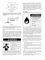
FORYOURSAFETYREADBEFORELIGHTING
!
I
I WARNING:Ifyoudonotfollowthe_instruc_ns
exa_ly,afireor explosionJ
=may resuffcausingproperty
damage,personalinjuryor IDesof life.
A,
Thisa_liance hasa pi_t whichis lighted_ a
_ezoelectfic_n_r_ Men iighting
thepilot,foliowthese
B_
BEFORELiGHTiNG
smellaNiaroundtheapplian_ area
for g_ Besuretosmellnextto thef_or _cause some
gasisheavi_thanair and_lNsoftieonthefiord
WHATTODOiFYOUSMELLGAS:
•
•
•
.
_
C, Useonlyyourhandto pushinor turn_e gascontrol
knob_N_er usetools_Ifthe knobwilln_ poshi_or
movebyhand,
don't
_ to_ir _ carla quai_ so.ice
technician,
Fore or attempted
repairmayresultin a fi_
or expl_ion_
Do notusethis
appliance
ifany_rthas_en under
_en !_diatehj calla qualifiedservicetechnician
to
insp_ theappliance.Waterheate_ subjected
tofl_d
conditions
or anytime_hegascontro|s,mainburneror
piio_have_en subme_ in wste__uire replace_t
of theentre waterheaten
_ nottryto tight anyappliance_
Donottouchanyelect_calswitch;do notuseany
_one in yourbuilding.
immediately
callyour gassuppl_r_m a
neigh_r'sphone.Follow_egassup_ier's
instructions.
ifyoucannotreachyour gassupplier,
callthefire
department,
E_
OONOTUSETHiSAP_IA_E iFTHEREHASBEEN
_N_ION OFVAPORS.
i
caNi
a
sewice
technician
toinspecttheappliance.
Waterheaters
sub_t_ toa tie.able vapo_ ignition_ll showa
discolorationon _e air intakegrid andrequi_
_eplacement
oftheentirewaterheater.
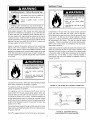
LIGHTINGINSTRUCTIONS
_OP_ _ isimper_dve
_= you_
_fore _ightingthepilot
aUthe_min_
7_
2. Removetheouterd_
3. Turnthet_perature dialco_nterc|c_kwise
_
to _s
Io_t se_n_.
R_:SET
BUniON
_
CON _"_OL
W_AL
Depresstheres_ button_ltthe _y
in and IMMEDIATELY
depress_e
igniterbuttonuntil youheara loud
click.Observethepilotthroughthe
viewport.Donot releasethereset
button,Repeatim_iately if _lot
doesnotNight
onthe first try.ffthe
piiotdoesnot Night
bythefourth
_empt _th _e igniter,repe_steps
4- 7.Continuetoholdthebu_onfor
a_ (_) _nute _er _e pi_t is !_:,
Rel_se theresetbud_on
and_ willpop
_ck up.Pilotshouldremainlit.ifthe
pi!otlightgoesout,repeatsteps3 _7.
PUSHBUTTON
_GNiTER
IMPORTANT:
Nfthe pilotwil!n_ staylit a_e__veral N_,
_press the_ia!stopand_m _s c_ro_ knobto "OFP,
then
c_!y_r _d_ _hn_ianor gassupplier,
4_
Depress
the dialstopandturn{_
gascontrolknobclockv,_
'tothe "OFF"pose|on,
NMPORTANT:
ifthe _s_ burn (seegraphicatstep3}does
notpop up _en reload, s_p andimmediately
shutoff
the gasatthe|insvalveortank_Callyourservicet_chnicbn
or gassuppl_n
Toc|earanygas_at _y have
accumulated
_it ten(10)minutes,
Ifyouthensmellgas,STOP!:
Follow_B"in thesafety
wa_inga_ve. ifyoudo notsmeUgasgo tothenext
step.
6_
8_ Turnthegascon_l knob
countercloc_se
to"ONe.
9_ Setthete_e_ture dialto
• e desiredse_ng.
Turnthegascontrolknob_
counterclockwise
to"PILOT",
_0_Replacetheout_er
door,
TO TURNOFFGASTOAPPLIANCE
Turnt_stempersturedialcounterc_ockwise_F_
to its
In.st settJng.
2, Turnthegascontrotknobciock_se_
pose|on,
18
tothe'_OFF
Temperature
NOTE: Awater temperature range of 120°F-140°F (49°C-60°C)
is recommended by most dishwasher manufacturers.
Regulation
The thermostat of this water heater has been factory set at its
lowest position. It is adjustable and must be reset to the desired
temperature setting for energy efficient operation at the minimum
water temperature setting that meets your hot water needs. To
reduce the risk of scald injury, 120°F (49°C)is preferred starting
point. Some states have a requirement for a lower setting.
Due to the nature of the typical gas water heater, the water
temperature in certain situations may vary up to 30F ° (16.7 C °)
higher or lower at the point of use such as, bathtubs, showers,
sink, etc.
o7:1[el ;t
Align the index bar on the thermostat
temperature as shown in Figure 21.
Water temperature over 125°F
(52°C) can cause severe burns
instantly resulting in severe injury
ordeath.
Children,
the
elderly,
are at highest riskforscald
and
Turn the water temperature dial clockwise ( t'_ ) to increase
the temperature, or counterclockwise ( _ ) to decrease the
temperature.
the
Should overheating occur or the gas supply fail to shut off, turn
off the manual gas control valve to the appliance.
injury.
_,___,_.
hysically
mentallybathing
disabledor
Feel
water or before
__
Temperature limiting valves are
available.
showering.
Read instruction manual for safe
temperature setting.
with the desired water
Robertshaw Gas Valve
%
_,,_,_Gas
Reset --4_[__,
Button
_=__
Control Knob
130°F
Dial Stop
Bar
140°F
_
_'(_)
Index
_=_(_)
]
I F_._:)WARNIN_
t
/
120°F
/Bar
i¢/
1500Bar ""__
Bar "_'A/
. b.UTIo4,
HOTTER WATER CAN SCALD: Water heaters are intended to
produce hot water. Water heated to a temperature which wilt
satisfy space heating, clothes washing, dish washing, and other
sanitizing needs can scald and permanently injure you upon
contact. Some people are more likely to be permanently injured
by hot water than others. These include the elderly, children,
the infirm, or physically/mentally handicapped. If anyone using
hot water in your home fits into one of these groups or if there is
a local code or state taw requiring a certain temperature water
at the hot water tap, then you must take special precautions. In
addition to using the lowest possible temperature setting that
satisfies your hot water needs, a means such as a mixing valve
should be used at the hot water taps used by these people or
at the water heater. Mixing valves are available at plumbing
supply or hardware stores. Follow manufacturer's instructions
for installation of the valves. Before changing the factory setting
on the thermostat See Figures 21 and 22.
_"_CZgY_
_--Temperature
FIGURE
Never allow small children to use a hot water tap, or to draw their
own bath water. Never leave a child or handicapped person
unattended in a bathtub or shower.
21.
160°F (71°C)
About 1/2 second
150°F (66°C)
About 1-1/2 seconds
140°F (60°C)
Less than 5 seconds
130°F (54°C)
About 30 seconds
120°F (49°C)
More than 5 minutes
80°F (27°C)
FIGURE
19
Dial'll_
22.
'_.. \
Tank (Sediment)
Cleaning
Burner
Flood damage to a water heater may not be readily visible or
immediately detectable. However, over a period of time a flooded
water heater will create dangerous conditions which can cause
DEATH, SERIOUS BODILY INJURY, OR PROPERTY DAMAGE.
Contact a Sears Service Center to replace a flooded water
heater. Do not attempt to repair the unit! It must be replaced!
Sediment build-up on the tank bottom may create varying
amount of noise and if left in the tank will cause permanent
tank failure. In some water areas, you may not be able to drain
all sediment deposits by simply draining the tank. In these
cases Mag-Erad (part no. 23600) can be used to help remove
the sediment deposits. This may be ordered from the Sears
Service Center. For ordering, refer to the Parts Order List
section.
Vent
System
Inspection
At least once a year a visual inspection should be made of the
main burner. See Figure 23.
t
Inspection
CORRECT FLAME
SOFT BLUE
Carbon Monoxide and Fire Ha_rd
• Fiue gases may esca_
is not connected,
if vent pipe
• Be ale_ for obstructed, sooted or
deteriorated vent system to avoid
serious injury or death,
, Do not store corrosive chemicals
in the vicinity of ,water heater°
• Chemi_ corrosion of flue and vent
system _n cause sedous, injury of
death,
FIGURE
Inspect burner flames through viewport. Flames should be very
small with a blue haze and small amounts of yellow or orange at
the edges. After several minutes of operation the burner screen
may glow red. If large flames are observed at anytime shut-off
unit and contact a Sears Service Center.
Breathing carbon monoxide can _ase brain damage or
death, Aiways read and understand instructionmanual
At least once a year a visual inspection should be made of the
venting system. You should look for:
•
Obstructions which could cause improper venting.
The
combustion and ventilation air flow must not be obstructed.
•
Damage or deterioration which could cause improper venting
or leakage of combustion products.
•
Rusted flakes around top of water heater.
23.
Be sure the vent piping is properly connected to prevent
escape of dangerous flue gasses which could cause deadly
asphyxiation.
Obstructions and deteriorated vent systems may present serious
health risk or asphyxiation.
Chemical vapor corrosion of the flue and vent system may occur
if air for combustion contains certain chemical vapors. Spray can
propellants, cleaning solvents, refrigerator and air conditioner
refrigerants, swimming pool chemicals, calcium and sodium
chloride, waxes, bleach and process chemicals are typical
compounds which are potentially corrosive.
If when inspecting
the vent system you find sooting or
deterioration, something is wrong. Call the local gas supplier to
correct the problem and clean or replace the flue and venting
before resuming operation of the water heater.
20
Removing
the Burner
1,
Turn off the gas to the water heater at the manual gas
shut-off valve (Figure 3).
2.
Turn the gas control knob on the combination gas control
valve/thermostat clockwise to the "OFF" position (Figure 1).
NOTE: Depress the dial stop on Robertshaw valve before
turning the gas control knob. See Lighting Instructions on
the water heater.
3,
4.
Ultra Low NOx Natural Gas Burner
Door Assembly
Check the burner to see if it is dirty or clogged. The burner
may be cleaned with soft paint brush (Figure 26). Do not use
a wire brush or any tool that may damage the burner screen.
Important: Do not use the burner if the burner screen is
damaged. NOTE: Damage may be rips or holes in the burner
screen. Discoloration is normal.
Remove the outer door.
Remove the two screws securing the burner door
assembly to the combustion chamber. (Figure 24).
GAS VALVE/
THERMOSTAT
f
PILOT ASSEMBLY
/
BURNER
USE BRUSH
ON THIS SURFACE
FIGURE 26.
DOOR
SCREW(2)
FIGURE
TWO PIECE WIRE
CONNECTOR
Replacing
24.
1,
5.
Disconnect the thermocouple (right-hand thread), pilot
tube, the igniter wire from the igniter button, and manifold
tube at the thermostat.
(Figure 25).
6.
Grasp the manifold tube and push down slightly to free
the manifold tube, pilot tube, and thermocouple.
7.
Carefully remove the burner door assembly from the
combustion chamber. Be sure not to damage internal
parts.
2.
3,
ROBERTSHAW
4,
5.
GAS VALVE
6,
7.
PILOT TUBE
8,
MANIFOLD
TUBE "_
FIGURE 25.
g,
21
the Pilot Assembly
Follow the instructions in "Removing the Burner Door
Assembly" section to remove the assembly.
Remove the retainer clip securing the two piece wire
connector to the burner door assembly. (Note the orientation
of the retainer clip). Insert the tip of a large flat head
screwdriver between the clip and the top of the two piece
wire connector. Carefully rotate the screwdriver to raise the
clip. It may be necessary to remove the connector one side
at a time. (See Figure 27.)
Locate where the thermocouple connects to the rear of the
pilot assembly, and pull the thermocoupte tip from the rear of
the pilot assembly.
Remove the nut securing the pilot assembly to the burner
and keep it for reuse later.
Use a 1/2" open end wrench, to loosen the nut securing the
pilot tube to the pilot. To prevent any bending use a pair of
pliers to steady the pilot bracket.
Remove the old pilot assembly (including the igniter wire)
from the burner door assembly.
Insert the pilot tube into the new pilot assembly. Important:
The new pilot assembly comes with an orifice. This orifice
must be installed when replacing the pilot assembly.
IMPORTANT: Do not operate this water heater without the
orifice in place.
Use a 1/2" open end wrench, to tighten the nut securing the
pilot tube to the pilot. To prevent any bending use a pair of
pliers to steady the pilot bracket.
Use the nut removed in a previous step to secure the new
pilot assembly to the burner.
10.
Insert the igniter wire through the burner door and reconnect
the thermocoupte to the pilot assembly. See "Replacing the
Thermocoupte" section.
11.
Reinstall the two piece wire connector. NOTE: The pilot
tube must be at the top followed by the igniter wire then the
thermocoupte.
12.
Follow the instructions in "Replacing the Burner Door
Assembly" section to reinstall the assembly.
Replacing
the Thermocouple
External Inspection
Flame Arrestor
1.
Remove the Burner Door Assembly as directed
previously.
2.
Remove the retainer clip from the back of the two piece
wire connector and remove the two piece wire connector
from the assembly (Figure 27).
3.
Pull the thermocoupte
(Figure 31 ).
& Cleaning
of the
Although not likely to occur, if debris collects on the flame
arrestor, use a vacuum, compressed air, or a soft bristle brush
to remove it. NOTE: If unable to inspect or clean the flame
arrestor from underneath, follow the "Cleaning the Combustion
Chamber and Flame Arrestor" section instructions.
from the pilot assembly
IMPORTANT: Be careful not to bend or alter the position of the
pilot assembly components.
4.
Push the new thermocouple through the holes in the
pilot bracket. Insert the thermocouple tube into the holes
provided in the pilot assembly until it clicks into place.
Leave a small straight section entering and leaving the
two piece wire connector section for easier removal/
service.
5.
Position the new thermocouple through the opening of
the two piece wire connector (Figure 27). NOTE: The pilot
tube should be located at the top followed by the igniter
wire then the thermocouple.
6.
See "Replacing the Burner Door Assembly" section.
PILOT
THERMOCOUPLE
TUBE
Flashlight
IGNITER
WIRE
RETAINER
TWO PIECE
WIRE CONNECTOR
CLIP
MANIFOLD
DOOR
FIGURE 27.
Cleaning
the Pilot Assembly
1.
Follow the procedure outlined in "Removing the
Burner Door Assembly".
2.
Use a soft bristle brush to remove any debris that
may have collected on the pilot. Note: Clean any
debris found in the primary air supply hole on the
pilot. See Figure 28.
3.
Follow the steps in "Replacing the Burner Door
Assembly" section to reassemble.
tGNITER_
Mirror
.
•
FIGURE
Cleaning the Combustion
Flame Arrestor
- _X PILOT BRACKET
FIGURE
1
"_
UL_b
_
\i
28.
22
•
29
Chamber
and
1,
Follow procedure outlined in "Removing the Burner Door
Assembly" section.
2,
Use a vacuum cleaner/shop vac to remove all loose
debris in the combustion chamber (Figure 30). Use
compressed air to clear any dust or debris that may have
accumulated in the flame arrestor.
3,
Reassemble following the procedure under the "Replacing
the Burner Door Assembly" section.
Replacing
the Burner Door Assembly
Fire or Explosion Hazard
* Tighten _th
@
manifold door screws securely.,
- Remove any fibe_Iass
combustion chamber.
between gasket and
,Repiace viewport if giass is missing or damaged,
* Replace two piece wire _nnector
removed,
GAS CONTROL
THERMOSTAT
if missing or
, Rep_a_ door gasket if damaged,
- FaJiure to foiiow these _nstructJons_
death, explosion, or fire,
BURNER
result in
VALVE
\
DOOR
ASSEMBLY
_
Read instruction manual before
installing, using or se_icing
water heater
FIGURE 30.
1.
9.
Check the door gasket for damage or imbedded debris
prior to installation.
Check for leaks by brushing on an approved noncorrosive
leak detection solution. Bubbles will show a leak. Correct
any leak found.
10. Replace the outer door.
Piezoelectric
Explosion Hazard
Igniter System
The piezoelectric igniter system consists of the igniter button,
electrode, and wire. The pilot is ignited by an electric spark
generated when the igniter button is pressed. The electrode
should be centered between the pilot and thermocouple. (See
Figure 31 ). Use only factory authorized piezoelectric igniter
parts for replacement.
, Replace viewpo_ if gUass is
missing or damaged,
• Failure to do so _n result in
death_ exp/[osion, or fire,
PILOT
PILOT
2.
Inspect the viewport for damage and replace as required.
3.
Insert the burner door assembly into the combustion
chamber and slide it completely forward. Note: When
inserting the burner door assembly, tip the burner end up
slightly to ensure it engages with the burner bracket.
4.
Inspect the door gasket and make sure there is no
fiberglass insulation between the door gasket and the
combustion chamber (See Figure 30).
5.
.IGNITER
Reconnect the manifold tubing, pilot tubing, and
thermocouple to the thermostat. Do not cross-thread
or apply any thread sealant to these fittings. The
thermocouple nut should be started and turned all the
way in by hand. An additional 1/2 - 3/4 turn with a 7/16"
open end wrench will then be sufficient to seat the
lockwasher.
7.
Reconnect the igniter wire.
8.
Turn gas supply on and refer to the "Operating Instructions".
\
BOTTON
ELECTRO
U
T ERMO U E
'--BNAP-ONCONNECTOR
Replace the two screws, which secure the burner door
assembly to the combustion chamber and tighten
securely. Once the burner door assembly is tightened,
visually inspect the door gasket between the burner door
assembly and the combustion chamber for spaces or
gaps that would prevent a seal. IMPORTANT: Do not
operate the water heater if the door gasket does not
create a seal between the burner door assembly and the
combustion chamber.
6.
_.
BRACKET
ELECTRODE
FIGURE 31.
Testing
the Igniter
System
Turn off the gas to the water heater at the manual gas shut-off
valve. Watch the electrode tip while activating the igniter. A
visible spark should jump from the electrode. To avoid shock,
do not touch the burner or any metal part on the pilot or pilot
assembly. If no spark is visible, check the wire connections
and make sure the electrode is not broken. Replace the
electrode if defective. NOTE: The electrode is part of the pilot
assembly and cannot be replaced separately. Dirt and rust on
the pilot or electrode tip can prevent the igniter spark. Wipe
clean with a damp cloth and dry completely. Rust can be
removed from the electrode tip and metal surfaces by lightly
sanding with an emery cloth or fine grit sandpaper.
23
Removing and Replacing
Valve/Thermostat
the Gas Control
Housekeeping
Vacuum around base of water heater for dust, dirt, and lint on
a regular basis.
IMPORTANT: The gas control valve/thermostat is a standard
valve with a right-hand thread thermocouple. Use only factory
authorized replacement parts.
Removing the Gas Control Valve/Thermostat:
Fire and Explosion Hazard
1.
• DO not obstruct _mbustion
air
o_nings
at the bottom of the
water heater.
Turn the gas control knob on the combination gas control
valve/thermostat clockwise to the "OFF" position. NOTE:
Depress the dial stop on Robertshaw valves before turning
the gas control knob. See Lighting Instructions on the water
heater.
2.
Turn off the gas at the manual shut-off valve on the gas
supply pipe (Figure 3).
3.
Drain the water heater. Refer to "Draining" section and
follow the procedure.
4.
Disconnect the igniter wire from the igniter. NOTE: First
remove the igniter from the bracket by depressing front
and rear holding tabs and lift. Next remove igniter bracket
from the gas control valve/thermostat. Disconnect the
thermocoupte (right-hand threads), pilot tube, and manifold
tube at the gas control valve/thermostat (Figure 25).
5.
6.
Do not use or store fl_ammable
vapor products such as gasoline,
solvents or adhesives in the
_me room or area near water
heater or other appliance,
• Visibly inspect _ame arrestor at
least on_ every six months and
clean if accumu_a_d Hnto
• Can cause
death,
serious
injury or
AT LEAST ONCE EVERY SiX MONTHS
A VISUAL
INSPECTION
SHOULD
BE MADE OF THE FLAME
ARRESTOR.
CLEAN IF LINT ACCUMULATIONS
ARE
NOTICED.
Refer to "Gas Piping" section and disconnect the ground
joint union in the gas piping. Disconnect the remaining
pipe from the gas control valve/thermostat.
INSTALLED IN SUITABLE AREA: To insure sufficient ventilation
and combustion air supply, proper clearances from the water
heater must be maintained. See Facts to Consider About the
Location section.
Combustible materials such as clothing,
cleaning materials, or flammable liquids, etc. must not be placed
against or adjacent to the water heater because they could
catch on fire.
To remove the gas control valve/thermostat, thread a
correctly sized pipe into the inlet and use it to turn the gas
control valve/thermostat (counterclockwise.) Do not use
pipe wrench or equivalent to grip body. Damage may
result, causing leaks. Do not insert any sharp objects into
the inlet or outlet connections. Damage to the gas control
valve/thermostat may result.
Anode
Rod Inspection
Replacing the Gas Control Valve/Thermostat:
To replace the gas control valve/thermostat, reassemble
in reverse order. When replacing the gas control valve/
thermostat, thread a correctly sized pipe into the inlet and use
it to turn the gas control valve/thermostat (clockwise. DO NOT
OVER TIGHTEN, damage may result.
•
Be sure to use approved Teflon ® tape or pipe joint
compound on the gas piping connections and fitting on
the back of the gas control valve that screws into tank.
•
Be sure to remove the pilot ferrule nut from the new gas
control valve/thermostat.
•
Turn the gas supply on and check for leaks. Test all
connections by brushing on an approved noncorrosive
leak-detection solution. Bubbles will show a leak. Correct
Property
•
• Inspection and replacement of anode rod required.
The anode rod is used to protect the tank from corrosion. Most
hot water tanks are equipped with an anode rod. The submerged
rod deteriorates to protect the tank. Instead of corroding the tank,
water ions attack and eat away the anode rod. This does not
affect the water's taste or color. The rod must be maintained to
keep the tank in operating condition.
EXPOSED
SUPPORT
WIRE\
_\
Be sure tank is completely filled with water before lighting
and activating the water heater. Follow the "Operating
Instructions"
®
\\
_
- _,_",tr_ _
"__t'l'_'# _i'l lll_
\\
LilIIIIII_"_'_
I IIIIIII1_
. _,_
" _'_ _
',_''_'a,',['J_
PITTED ANODE
_7£"_...,,,_,.J1_1=,_,_
_ #_'_ _ ¢__
.......
\\
't
_ _ _,_'_t_EXPOSED
= _l,_'%,,_ ,t_.,t_. _" _' SUPPORT
ROD----------------"
FIGURE
If additional information is required, contact Sears Service
at: 1-800-4-MY-HOME ® (1-800-469-4663).
TEFLON
Hazard
- Avoid water heater damage.
any leak found.
•
Damage
WIRE
32
Anode deterioration
depends on water conductivity,
not
necessarily water condition. A corroded or pitted anode rod
indicates high water conductivity and should be checked and/
is a registered trademark of E.I. Du Pont De Nemours and Company.
24
or replaced more often than an anode rod that appears to be
intact. Replacement of a depleted anode rod can extend the
life of your water heater. Inspection should be conducted by
calling the Sears Service Center for an authorized contractor.
At a minimum, the anode(s) should be checked annually after
the warranty period.
Temperature-Pressure
The temperature-pressure
at least once a year.
The water heater should be drained if being shut down during
freezing temperatures. To drain the tank, perform the following
steps:
Turn off the gas to the water heater at the manual gas
shut-off valve.
2.
Open a nearby hot water faucet until the water is no longer
hot.
Relief Valve Operation
relief valve must be manually operated
If'.,•w7..I [e] ::1;I
1.
3.
Close the cold water inlet valve.
4.
Connect a hose to the drain valve and terminate it to an
adequate drain or external to the building.
5.
Open the water heater drain valve and allow all of the water
to drain from the tank. Flush the tank with water as needed
to remove sediment.
6.
Close the drain valve, refill the tank, and restart the heater
as directed in this manual.
• Bum hazard
• Hotwater discharge.
If the water heater is going to be shut down for an extended
period, the drain valve should be left open.
• Keep clear of relief valve
discharge outlet.
IMPORTANT: Condensation may occur when refi Iling the tank
and should not be confused with a tank leak.
Follow the lighting instructions in the Lighting section to restart
the water heater.
When checking the temperature-pressure relief valve operation,
make sure that (1) no one is in front of or around the outlet of
the temperature-pressure relief valve discharge line, and (2) that
the water discharge will not cause any property damage, as the
water may be extremely hot, see Figure 33.
Drain Valve Washer
Replacement
(See Figure 34)
1. Turn "OFF" gas supply to water heater.
TEMPERATURE-PRESSURE
2. Follow "Draining" instructions.
RELIEF VALVE
3. Turning counter clockwise (('_),
remove the cap.
4. Unscrew the stem by turning it counter clockwise ( _
remove it from the drain valve body.
), and
5. Remove the bottom washer and put the new one in place.
DISCHARGE
PIPE
6. Re-insert the stem into the drain valve body and retighten the
cap to the body using a wrench. DO NOT OVER TIGHTEN.
FIGURE 33.
If after manually operating the valve, it fails to completely reset
and continues to release water, immediately close the cold water
inlet to the water heater, follow the draining instructions, and
replace the temperature-pressure
relief valve with a new one.
7. Follow instructions in the Filling The Water Heater section.
8. Check for leaks.
9. Follow the lighting instructions in the Lighting section to restart
the water heater.
If the temperature-pressure
relief valve on the appliance weeps
or discharges periodically, this may be due to thermal expansion.
You may have a check valve installed in the water line or a water
meter with a check valve. Consult the Sears Service Center
for further information.
relief valve.
Do not plug the temperature-pressure
Draining
mY,.,I[€.]::1;I
FIGURE
• Burn hazard
34.
Service
• Hotwater discharge.
Before calling for repair service, read the Start Up Conditions
and Operational Conditions found in the Troubleshooting Guide
of this manual.
• Keep hands clear of drain
valve discharge.
If a condition persists or you are uncertain about the operation of
the water heater, let the Sears Service Center check it out.
Contact Sears Service Center at:
It is recommended that the tank be drained and fl ushed every 6
months to remove sediment which may build up during operation.
1-800-4-MY-HOME
25
®
(1-800-469-4663).
NOTE: Expansion tanks are pre-charged with a 40 psi air
charge. If the inlet water pressure is higher than 40 psi, the
expansion tank's air pressure must be adjusted to match
that pressure, but must not be higher than 80 psi.
Start Up Conditions
Thermal
Expansion
Property
Damage
HOT
Hazard
WATER HEATER
COLD WATER
INLET FITTING
COLD
(3)
PRESSURE
REDUCING
VALVE WITH
BY-PASS
• Avoid water heater damage.
• Install thermal expansion tank or device if necessary.
• Contact qualified installer or service agency.
As water is heated, it expands (thermal expansion). In a closed
system, the volume of water wilt grow. As the volume of water
grows, there wilt be a corresponding increase in water pressure
due to thermal expansion. Thermal expansion can cause
premature tank failure (leakage). This type of failure is not
covered under the limited warranty. Thermal expansion can also
cause intermittent temperature-pressure
relief valve operation:
water discharged from the valve due to excessive pressure build
up. The temperature-pressure
relief valve is not intended for the
constant relief of thermal expansion. This condition is not covered
under the limited warranty.
(2)
INLET COLD
PRESSURE GAUGE
WATER
SHUT-OFF
RECOMMEN DED INSTALLATION
(VERTICAL MOUNTING)
WATER HEATER
COLD WATER
INLET FITTING
HOT
FLOOR, CEILING JOIST, ETC.
COLD
STRAPPING
A properly-sized thermal expansion tank should be installed
on all closed systems to control the harmful effects of thermal
expansion. Contact a plumbing service agency or your retail
supplier regarding the installation of a thermal expansion tank.
Table 1 : Thermal
Expansion
Tank
Model
Number
153.331020
153.331050
Capacity
In Gallons
2
5
Tank Specifications
Dimensions
in inches
Diameter
8 (203 mm)
Len£1th
12-3/4 (323 mm)
Pipe
Fitting
On Tank
3/4" Male
11 (279 mm)
14-3/4 (375 mm)
3/4" Male
PRESSURE GAUGE
I
f
/
t
INLET COLD
WATER SHUT-OFF
ALTERNATE RECOMMENDED INSTALLATION
(HORIZONTAL MOUNTING)
FIGURE
35.
Table 2: Expansion Tank Sizing Chart
Inlet*
Water
Pressure
Expansion
Tank
Capacity
Needed
Water Heater Capacity
Strange Sounds
(Gallons)
30
40
50
66
82
40 psi
2
2
2
5
5
50 psi
2
2
2
5
5
60 psi
2
2
2
5
5
70 psi
2
2
5
5
5
80 psi
2
5
5
5
5
Possible noises due to expansion and contraction of some metal
parts during periods of heat-up and cool-down do not represent
harmful or dangerous conditions.
Condensation causes sizzling and popping within the burner area
during heating and cooling periods and should be considered
normal. See Condensation section.
*Highest recorded inlet water pressure in a 24 hour period or
regulated water pressure.
Draft Hood Operation
Check draft hood operation by performing
a worst case
depressurization of the building. With all doors and windows
closed, and with all air handling equipment and exhaust fans
operating such as furnaces, clothes dryers, range hoods and
bathroom fans, a match flame should still be drawn into the
draft hood of the water heater with its burner firing. If the flame
is not drawn toward the draft hood after 15 minutes of burner
operation, shut off water heater and make necessary air supply
changes to correct.
26
Condensation
Whenever the water heater is filled with cold water, some
condensate will form while the burner is on. A water heater may
appear to be leaking when in fact the water is condensation. This
usually happens when:
•
A new water heater is filled with cold water for the first time.
•
Burning gas produces
water vapor In water heaters,
particularly high efficiency models where flue temperatures
are lower.
•
•
a concentration of sulfate in the supply water.
little or no dissolved oxygen in the water.
•
a sulfate reducing bacteria within the water heater. (This
harmless bacteria is non-toxic to humans.)
•
an excess of active hydrogen in the tank. This is caused by
the corrosion protective action of the anode.
Smelly water may be eliminated or reduced in some water heater
models by replacing the anode(s)with one of tess active material,
and then chlorinating the water heater tank and all hot water
lines. Contact Sears Service for further information concerning
an Anode Replacement Kit #9001453 and this Chlorination
Treatment. Anode replacement and chlorination of the tank are
not covered by the water heater's limited warranty.
• Large amounts of hot water are used in a short time and the
refill water in the tank is very cold.
Moisture from the products of combustion condense on the
cooler tank surfaces and form drops of water which may fall
onto the burner or other hot surfaces to produce a "sizzling" or
"frying" noise.
If the smelly water persists after the anode replacement and
chlorination treatment, it may be necessary to chlorinate or aerate
your water supply to eliminate the problem.
Do not remove the anode leaving the tank unprotected. By
doing so, all warranty on the water heater tank is voided.
Excessive condensation can cause pilot outage due to water
running down the flue tube onto the main burner and putting
out the pilot.
"AIR" In Hot Water Faucets
Because of the suddenness and amount of water, condensation
water may be diagnosed as a "tank leak". After the water in
the tank warms up (about 1-2 hours), the condition should
disappear.
\
Explosion
Do not assume the water heater is leaking until there has been
enough time for the water in the tank to warm up.
An undersized
• Flammable
hydrogen
gases may be present.
water heater will cause more condensation.
The water heater must be sized properly to meet the family's
demands for hot water including dishwashers, washing machines
and shower heads.
• Keep all ignition sources
away from faucet when
turning
on hot water.
Excessive condensation may be noticed during the winter and
early spring months when incoming water temperatures are at
their lowest.
HYDROGEN GAS: Hydrogen gas can be produced in a hot
water system that has not been used for a long period of time
(generally two weeks or more). Hydrogen gas is extremely
flammable and explosive. To prevent the possibility of injury
under these conditions, we recommend the hot water faucet,
located farthest away, be opened for several minutes before
any electrical appliances which are connected to the hot water
system are used (such as a dishwasher or washing machine).
If hydrogen gas is present, there wilt probably be an unusual
sound similar to air escaping through the pipe as the hot water
faucet is opened. There must be no smoking or open flame near
the faucet at the time it is open.
Good venting is essential for a gas fired water heater to operate
properly as well as to carry away products of combustion and
water vapor.
Smoke Odor
It is not uncommon to experience a small amount of smoke and
odor during the initial start-up. This is due to burning off of oil
from metal parts, and wilt disappear in a short while.
Operational
Smelly
Hazard
Conditions
Odor
High
In each water heater there is installed at least one anode rod (see
parts section) for corrosion protection of the tank. Certain water
conditions wilt cause a reaction between this rod and the water.
The most common complaint associated with the anode rod is
one of a "rotten egg smell". This odor is derived from hydrogen
sulfide gas dissolved in the water. The smell is the result of four
factors which must all be present for the odor to develop:
Temperature
Shut
Off System
This water heater is equipped with an automatic gas shutoff
system. This system works when high water temperatures
are present. The high temperature shutoff is built into the gas
control valve. It is non-resettable. If the high temperature shutoff
activates, the gas control valve must be replaced. Turn "OFF"
the entire gas supply to the water heater and contact your gas
supplier.
27
PROBLEM
CORRECTIVE
POSSIBLE CAUSE(S)
ACTION
BURNER WILL NOT IGNITE
1.
2.
3.
4.
5.
6.
7.
8.
9.
Pilot not tit
Thermostat set too low
No gas
Dirt in the gas lines
Pilot tine clogged
Main burner line clogged
Non-functioning thermocouple
Non-functioning thermostat
Heater installed in a confined area
1.
2.
3.
4.
5.
6.
7.
8.
9.
Light pilot
Turn temp. dial to desired temperature
Check with gas utility company
Notify utility-install trap in gas line
Clean, locate source and correct
Clean, locate source and correct
Replace thermocouple
Replace thermostat
Provide fresh air ventilation
SMELLY WATER
1.
Sulfides in the water
1.
Replace the anode with a special anode
PILOT WILL NOT LIGHT
1.
2.
3.
4.
5.
6.
7.
8.
Air in gas line
No gas
Dirt in gas lines
Pilot line or orifice clogged
Cold drafts
Thermostat ECO switch open
Non-functioning igniter
Flammable vapor incident
1.
2.
3.
4.
5.
6.
7.
8.
11. Pilot dirty
Bleed the air from the gas line
Check with gas utility company
Notify utility-install dirt trap in gas line
Clean, locate source and correct
Locate source and correct
Replace thermostat
Replace igniter pilot assembly
Eliminate flammable vapor source(s)
Call 1-800-4-MY-HOME ® (1-800-469-4663)
9. Check with gas utility company
10. See service and adjustment section for
inspection and cleaning of flame arrestor
& burner
11. Clean pilot
1.
2.
3.
4.
5.
6.
7.
Air in gas line
Dirt in gas lines
Pilot tine or orifice clogged
Thermocoupte connection loose
Non-functioning thermocouple
Cold drafts
Flammable vapor incident
1.
2.
3.
4.
5.
6.
7.
8.
9.
Low gas pressure
Air for combustion obstructed
9.
Low gas pressure
10. Air for combustion obstructed
PILOT WILL NOT REMAIN LIT
HIGH OPERATION COSTS
INSUFFICIENT
HOT WATER
SLOW HOT WATER
RECOVERY
10. Pilot dirty
Bleed the air from the gas line
Notify utility-install dirt trap in gas line
Clean, locate source and correct
Finger tighten; then 1/2 turn with wrench
Replace thermocoupte
Locate source and correct
Eliminate flammable vapor source(s)
Call 1-800-4-MY-HOME ® (1-800-469-4663)
8. Check with gas utility company
9. See service and adjustment section for
inspection and cleaning of flame arrestor
& burner
10. Clean pilot
1.
2.
Thermostat set too high
Sediment or lime in tank
1.
2.
3.
4.
Water heater too small for job
Wrong piping connections
3.
4.
5.
6.
7.
8.
9.
Leaking faucets
Gas leaks
Wasted hot water
Long runs of exposed piping
Hot water piping in exposed wall
5.
6.
7.
8.
9.
1.
2.
Thermostat set too tow
Sediment or lime in tank
1.
2.
3.
4.
Water heater too small
Wrong piping connections
3.
4.
5.
6.
7.
8.
9.
Leaking faucets
Wasted hot water
Long runs of exposed piping
Hot water piping in outside wall
Low gas pressure
5
6.
7.
8.
9.
1.
Insufficient
1.
2.
3.
4.
5.
6.
7.
Flue clogged
Low gas pressure
Improper calibration
Thermostat set too tow
Water heater too small
Wrong piping connections
2.
3.
4.
5.
6.
7.
8.
Wasted hot water
8.
air
28
Set temperature dial to lower setting
Drain/flush-provide water treatment if
needed
Install adequate heater
Correct piping-dip tube must be in cold
inlet
Repair faucets
Check with utility-repair at once
Advise customer
Insulate piping
Insulate piping
Turn temperature dial to desired setting
Drain/flush-provide water treatment if
needed
Install adequate heater
Correct piping-dip tube must be in cold
inlet
Repair faucets
Advise customer
Insulate piping
Insulate piping
Check with gas utility company
Provide ventilation to water heater.
Check flue way, flue baffle, and burner
Clean flue, locate source and correct
Check with gas utility company
Replace thermostat
Turn temperature dial to desired setting
Install adequate heater
Correct piping-dip tube must be in cold
inlet
Advise customer
PROBLEM
DRIP FROM RELIEF VALVE
POSSIBLE CAUSE(S)
CORRECTIVE
ACTION
1.
Excessive water pressure
1.
2.
Closed water system
2.
Use a pressure reducing valve and relief
valve
See "Thermal Expansion"
THERMOSTAT
SHUT OFF
FAILS TO
1.
2.
Non-functioning thermostat
Improper calibration
1.
2.
Replace thermostat
Replace thermostat
COMBUSTION
ODORS
1.
Insufficient
1.
2.
3.
Water heater flue or vent system blocked.
Heater installed in a confined area
2.
3.
Provide ventilation to water heater.
Check flue
way, flue baffle, and burner
Clean, locate source and correct
Provide fresh air ventilation
SMOKINGAND CARBON
FORMATION (SOOTING)
1.
Flammable vapor incident
1.
Call 1-800-4-MY-HOME ® (1-800-469-4663)
CONDENSATION
1.
Temperature setting too low
1.
Increase the temperature setting
BURNER FLAME FLOATS
AND LIFTS OFF PORTS
1.
2.
3.
Orifice too large
High gas pressure
Water heater flue or vent system blocked.
1.
2.
3.
4.
5.
Cold drafts
Dirty burner screen
4.
5.
Replace with correct orifice
Check with gas utility company
Clean flue and burner-locate source and
correct
Locate source and correct
Clean burner screen. See "Ultra Low
NOx Natural Gas Burner" section of this
manual.
FLAME BURNS AT ORIFICE
1.
2.
3.
Non-functioning thermostat
Low gas pressure
Non-functioning burner
1.
2.
3.
Replace thermostat
Check with gas utility company
Replace burner assembly
PILOT FLAME TOO SMALL
1.
2.
3.
Pilot line or orifice clogged
Low gas pressure
Dirty pilot
1.
2.
3.
Clean, locate source and correct
Check with gas utility company
Clean pilot
air
29
Section A: Pilot light will not light.
Section B: Pilot light will not remain lit or repeatedly goes out.
• ICheck the manual gas shut-oft valve to
I
Disthe gas turned on? I_NO mplsee if it is in the open position, if it is open
YES
I
" Ithen contact the gas utility company.
Have you bled all the air
from the pilot tube and
gas supp y ne?
YES
Is the thermocouple securely |
connected to the gas control _NO
IWhile repeatedly depressing the igniter button,
| NO •l
hold. down
the reset button until the pilot is lit and
.
Im
mPl' Imaintains a stable flame, then slowly release the
/
reset button.
I
+
Is the igniter producing a
spark?
YES
/ NO ILIFollow
the Testing the Igniter System l
....
_
_1 'nstruct'ons 'n th's manua'
I
Is the pilot tube and/or orifice /
free from d rt and debr s?
_NO
YES
--
Ivalve/therm°stat?
/
I Make sure the thermoceuple is securely I
mml,lcennected. Finger tighten then give a
I
--ladditional
1/2 turn with a wrench.
I
YES
,,!,,
Test the thermocouple using the following procedure: Disconnect the thermocouple
from the gas control valve/thermostat. Using a multimeter with alligator clip leads,
attach the red lead to the body (copper part) of the thermocouple. Attach the black
lead to the end (silver part) of the thermocouple that connects to the gas control valve/
thermostat. Follow the instruction to light the pilot and watch the voltage readings on
the multimeter. After 45 seconds the meter should read 12 millivolts DC or more.*
_k
I Follow the Replacing the Pilot Assembly
I
• l instructions found in this manual to access I
_
pilot tube and orifice. Clean as needed and
i
re nsta p ot tube and or f ce.*
IDoesthe thermocouple
YES
•lls
the thermoceuple fully
pass the test?_NO.plseated
YES
in the pilot bracket?
NO
I
I
÷
Is the pilot free from dirt and iiNO
debt s?
F
YES
Jk
-iv
Follow the Cleaning the Pilot Assembly
instructions found in this manual,*
IReplace the thermocouple. I
I
I
_r
+
I Follow the Replacing the Pilot Assembly
Is the pilot tube and/or orifice / NO • l instructions found in this manual to access
Ifree_from dirt and debris?
_
_
pilot tube and orifice. Clean as needed and
Is the pilot protected from cold |
klEliminate
drafts ghtng.
that could prevent it
from
YES
_"Site
-Bin
thisLocation"
manual. instructions found
rNO
any drafts. See the
YES
--
|
reinstall pilot tube and orifice.*
÷
Iisthe_ pilot
free from dirt and debris?
I'iNO
YES
Remove the burner door assembly.
Is the flame arrestor free from dirt or
debris? See "Removing the Burner
Door Assembly" section of the manual
lfor removal instructions.*
YES
ICheck the water heater for a Flammable
forward until it is fully seated
the pilot bracket and retest.
Push the thermocouple
in
ihl• IFollow the Cleaning the Pilot Assembly
qr'linstructions
found in this manual.*
/
I
I
,I,
Clean the flame arrestor
with a soft bristle brush
or vacuum cleaner.
lCheck for insufficient combustion
air. I
Are there openings for
l
• IInstall correct size make-up air openings per the I
make-up air to enter the _NO _lCombustion
Air and Ventilation section in this
room?
J
imanual.
YES
I
Vapor (FV) event. I
+
!,
Are the openings of sufficient size?
If the flame arrestor show signs of discoloration, shut-off the gas
I supply to the water heater at the manual gas shut-off valve, then
I contact Sears Service at: 1-800-4-MY-HOME
_ (1-800-469-4663).
I
i
• iCorrect size of openings to 1
thisSee
manualC°mbusti°nfor
requirements.Air
and Ventilation section in rNO
I
mplallo w sufficient air.
l
YES
÷
=NO, Is there a furnace/air
YES
handler in the same room as the water heater? I
÷
Does the return air duct for the furnace/
air handler draw its air from a separate
location than the water heater? See Facts
to ConsiderAbout the Location section and
IContact a local Heating,
I
.
' Air-Conditioningl
.
.
• IVentilation
_1 & Refngeratlon authorized I
iNO
the Combustion Air section.
YES
IIs there proper drafting at the
|service
/
draff hood? See Draft Hood
_NO
IOperation section in this manual. |
YES
provider.
Check the vent system for
Irestrictions/obstructions
and check
mml_the vent termination height. Refer to
tithe
Installation Instructions section of
|this manual for specific requirements.
Remove the burner door
. iRefer to the Service and Adjustment
I
assembly. Is the flame arrestor
=NO m_!,|section of this manual for information on I
and burner free from debris due to
--|cleaning
the flame arrestor and burner. I
|excessive lint, dirt, dust or oil?
YES
Y_S
i Does the flame arrestor show signs of discoloration. _NO
Shut-off the gas supply to the water heater at the
manual gas shut-off valve, then contact Sears
i Service at:
1-800-4-MY-HOME ® (1-800-469-4663).
* This procedure
requires the removal of water heater components.
3O
va ve/thermostat.*
1 Replace the gas control
I
POWER
MISER
6 GAS WATER HEATER
TM
Alternate anode
location for tc
T&P
153.330632
30 Gallon
153.330642
40 Gallon
153.330620
153.330652
40 Gallon (Short)
50 Gallon
Anode location
for side
-.@
Model Numbers
Key No.
*
**
***
Part Description
153.330632
153.330642
153.330620
153.330652
185917-001
185917-001
185917-001
185917-001
Heat Trap (Cold) - Some Models
9003915
9003915
9003915
9003915
3
Heat Trap (Hot) - Some Models
9003915
9003915
9003915
9003915
4
Cold Water Dip Tube
9006431
9002432
9003473
9002059
5
Anode
9003892
9003892
9003944
9003892
6
T & P Relief Valve (Located
9000071
9000071
9000728
9000071
7
Drain Valve
9000254
9000254
9000058
9000254
8
Gas Control
9006438
9006439
9006440
9006439
9
Outer Door
700795-018
700795-018
700795-018
700795-018
10
Pilot Assembly
11
Burner Door Assembly
12"
13
Two Piece Wire Connector
Burner Door Gasket
14
Viewport
15
Thermocouple
16
Piezoelectric
17
Flexible Manifold
1
Draft Hood
2
Rod
Top Or Side)
Valve/Thermostat
(Natural
Gas)
(Natural
Gas/Low
With Retainer
9006441
9006441
9006951
9006441
Nox)**
9006442
9006443
9006952
9006444
Clip
9006449
9006141
9006449
9006141
9006449
9006141
9006449
9006141
9006142
9006142
9006142
9006142
9000056
9000056
9000056
9000056
9006143
9006143
9006143
9006143
9006445
9006445
9006445
9006445
186190-002
186190-002
186190-002
Assembly
Igniter Button
Tube***
18*
Instruction Manual
186190-002
Not Shown.
Includes Inner Door Gasket
Flexible manifold tube sold as a separate part (burner not included).
Now that you have purchased your gas water heater, should a need
ever exist for repair parts or service, simply contact any Sears Service
Center or call 1-800-4-MY-HOME
<_(1-800-469-4663).
Be sure to
provide all pertinent facts when you call or visit.
WHEN
ORDERING
REPAIR
FOLLOWING
INFORMATION:
PARTS,
ALWAYS
GIVE
•
MODEL
NUMBER
•
SERIAL
NUMBER
•
TYPE GAS - NATURAL
•
PART DESCRIPTION
THE
THIS IS A REPAIR
31
PARTS
LIST, NOT A PACKING
LIST.
6 - YEAR
LIMITED
WARRANTY
ON WATER
HEATER
For six years from the date of purchase, if this water heater is installed and operated in a single-family
the owner's manual instructions and all local applicable plumbing codes, Sears will:
home in accordance
with
Supply free water heater parts for those that are defective in material or workmanship.
Supply a free water heater for one that develops a leak.
For the second
through
For commercial,
the sixth year from purchase
institutional,
years. During the second
industrial,
date, you must pay the labor cost for installation
or residential
use by two or more families,
the above
of parts or water heater.
limited warranty
1 -YEAR
EXCLUSIVE
KENMORE
LABOR
WARRANTY
For the first year from the date of purchase, Sears will, free of charge, supply and install new water heater
ones or a new water heater for one that develops a leak.
WARRANTY
To obtain warranty
is only for two
year you must pay the labor cost for parts or water heater installation.
service,
call 1-800-4-MY-HOME
This warranty
applies
only while this product
This warranty
gives you specific
parts for defective
SERVICE
® (1-800-469-4663).
is in use in the United States.
legal rights, and you may also have other rights which vary from state to state.
Sears, Roebuck and Co., Dept. 817WA, Hoffman Estates, IL 60179
The price of your water heater does not include a free checkup service call. On water heater
warrants the installation.
A charge will be made on service calls due to poor or incomplete installation. These include:
a. Adjusting thermostat
c. Leaks in pipes or fittings
e. Condensation
b. Lighting pilot
d. Improper venting
MASTER PROTECTION
AGREEMENTS
installations
arranged
Congratulations
on making a smart purchase. Your new Kenmore ®
product
is designed
and manufactured
for years of dependable
operation. But like all products, it may require preventive maintenance
on products
or repair from time to time. That's when having a Master Protection
Agreement can save you money and aggravation.
Power surge protection
fluctuations.
against electrical
Rental reimbursement
longer than promised.
if repair
Purchase
a Master
from unexpected
Protection
Agreement
now and protect
hassle and expense.
The Master Protection Agreement also helps extend the life of your
new product. Here's what's included in the Agreement:
•
Expert Service
by our 12,000 professional
•
Unlimited
service
covered repairs.
•
"No-lemon"
guarantee - replacement of your covered product
four or more product failures occur within twelve months.
•
Product
•
Annual
and
replacement
Preventive
no charge
if your covered
Maintenance
repair specialist.
for parts
and labor
on all
product can't be fixed.
Check at your request-
Fast
help
by phone
- phone
support
from
a Sears
SEARS
repair,
Roebuck
convenient
damage
of your covered
repair
due to power
product
takes
Once you purchase the Agreement,
a simple phone call is all that it
takes for you to schedule service. You can call anytime day or night,
or schedule
a service appointment
online.
Sears has over 12,000 professional
repair specialists,
access to over 4.5 million quality parts and accessories.
kind of professionalism you can count on to help prolong the
new purchase for years to come. Purchase your Master
Agreement today!
who have
That's the
life of your
Protection
Some limitations and exclusions apply. For prices and additional
information call 1-800-827-6655.
SEARS INSTALLATION SERVICE
technician
For Sears professional Installation of home appliances, garage door
openers, water heaters, and other major home items, in the U.S.A.,
call 1-800-4-MY-HOME
®.
For in-home major brand repair service
Call 24 hours a day, 7 days a week (U.S.A. and Canada)
1-800-4-MY-HOME
®
(1-800-469-4663)
www.sears.com
The model number of your water heater is found on the model rating plate on the front of the water heater.
Sears,
plus
no extra
charge.
•
if
in-home
scheduling.
•
yourself
requiring
by Sears, Sears
and Co., Hoffman
Estates,
IL 60179 U.S.A