1
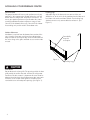
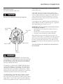
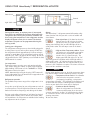
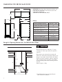
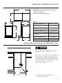
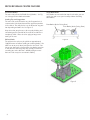
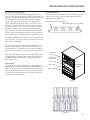
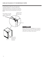
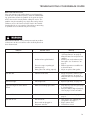
RANGEMASTER REFRIGERATED BEVERAGE CENTRE
Installation
Operation
and
Maintenance
Instructions
Refrigerated
Beverage Centre with
MicroSentry™ Refrigeration Monitor
RBC38
RBC60
TABLE OF CONTENTS
Unpacking your refrigerator............................................ 2
Removing the packaging............................................. 2
Warranty Registration .................................................. 2
Installing your refrigerator............................................... 3
Selecting the location.................................................. 3
Cabinet Clearances .................................................... 3
Leveling legs .............................................................. 3
Electrical Connection ..................................................... 4
Using Your MicroSentry™ Control................................... 5
Dimensions for RBC38 glass door................................... 7
Recommended Rough in Opening Dimensions
for RBC38 glass door.................................................. 7
Dimensions for RBC60 glass door................................... 8
Recommended Rough in Opening Dimensions
for RBC60 glass door.................................................. 8
RBC38 Features ............................................................ 9
RBC60 Features ............................................................ 10
Energy Saving Tips ......................................................... 11
Care and Cleaning ....................................................... 12
Cleaning condenser air flow........................................ 12
Cleaning the cabinet................................................... 12
Cleaning the interior.................................................... 12
Cleaning the pull out racks.......................................... 12
Cleaning the glass door .............................................. 12
Cleaning the door gasket............................................ 12
Replacing the light bulb............................................... 12
Aligning the door ....................................................... 13
Troubleshooting Guide................................................... 14
Obtaining Service ......................................................... 15
Guarantee .................................................................... 16
Appendix A additional MicroSentry™ features.................. 17
NOTE
This appliance is not intended for use by persons (including
children) with reduced physical, sensory, or mental capabilities, or lack of experience and knowledge, unless they have
been given supervision or instruction concerning use of the
appliance by a person responsible for their safety.
This product contains the following fluorinated greenhouse gases.
• HFC245fa - GWP = 950
• HFC134a - GWP = 1300
1
UNPACKING YOUR BEVERAGE CENTRE
Important Safety Instructions
Warnings and safety instructions appearing in this guide
are not meant to cover all possible conditions and situations
that may occur. Common sense, caution, and care must
be exercised when installing, maintaining, or operating this
appliance.
Recognize Safety Symbols,
Words, and Labels.
Note to Customer
This merchandise was carefully packed and thoroughly
inspected before leaving our plant. Responsibility for its safe
delivery was assumed by the retailer upon acceptance of
the shipment. Claims for loss or damage sustained in transit
must be made to the retailer.
DO NOT RETURN DAMAGED MERCHANDISE TO THE
MANUFACTURER - FILE THE CLAIM WITH THE RETAILER.
result in personal injury or property or product damage.
If the unit was shipped or has been laying on its back for
any period of time allow the refrigerator to sit upright for a
period of at least 24 hours before plugging in. This will assure oil returns to the compressor. Plugging the refrigerator
in immediately may cause damage to internal parts.
WARNING-Hazards or unsafe practices which could
Warranty Registration
CAUTION-Hazards or unsafe practices which could
result in personal injury.
NOTE
NOTE-Important information to make a problem free
installation.
Remove Packaging
Your refrigerator has been packed for shipment with all
parts that could be damaged by movement securely fastened. Cut the banding material at the bottom of the carton,
unfold the carton at the bottom and remove the carton from
the appliance. Remove the plastic bag, styrofoam corner
posts, and any tape holding the door closed and internal
components in place. The owners manual is shipped inside
the refrigerator in a plastic bag along with the warranty
registration card.
Important
Keep your carton packaging until your refrigerator has been
thoroughly inspected and found to be in good condition. If
there is damage, the packaging will be needed as proof of
damage in transit. Afterwards please dispose of all items
responsibly in particular the plastic bags which can be a suffocation hazard.
It is important to register your product as soon as possible
after taking delivery of your wine storage unit. You can register online at www.rangemaster.co.uk.
The following information will be required when registering
your unit.
Model Number
Serial Number
Date of Purchase
Supplier’s name and address
Installer’s name and address
The model number and serial number can be found on the
data badge which is located inside the refrigerator on the
left side toward the top of the cavity.
Help Prevent Tragedies
Child entrapment and suffocation are not problems of the
past. Junked or abandoned refrigerators are still dangerous.
Even if they sit out for “just a few days”.
If you are getting rid of your old refrigerator, please follow
the instructions below to help prevent accidents.
Before you throw away your old refrigerator or freezer:
• Take off the doors or remove the drawers.
• Leave the shelves in place so children may not easily
climb inside.
2
INSTALLING YOUR BEVERAGE CENTRE
Select Location
The proper location will ensure peak performance of your
appliance. We recommend a location where the unit will
be out of direct sunlight and away from heat sources. To
assure your product performs to specifications the recommended installation location temperature range is from
18 to 27°C for indoor built in units, 18 to 32°C for indoor
freestanding units, and 4 to 38°C for outdoor units.
Leveling Legs
Adjustable legs at the front and rear corners of the unit
should be set so the unit is firmly positioned on the floor and
level from side to side and front to back. Turn leveling legs
clockwise to raise unit, counterclockwise to lower it. (See
Figure 1).
Cabinet Clearance
Ventilation is required from the bottom front section of the
unit. Keep this area open and clear of any obstructions.
Adjacent cabinets and counter top can be installed around
the unit as long as the grille and door access remain unobstructed.
Front Grille,
keep this
area open.
Figure 1
Leveling Legs
Front Grille
Do not obstruct the front grille. The openings within the front
grille provide air to flow into and exit from the refrigerator
condenser. For this reason it is important this area to not be
obstructed and be kept clean. Rangemaster does not recommend the use of custom made grilles as air flow may be
restricted because of inadequate openings. (See Figure 1).
3
ELECTRICAL CONNECTION
13A must be used and fitted with a 13A fuse “ASTA” approved to BS 1363.
Electrical Connection
Use nominal 230 VAC, 50 Hz only.
Do not use an extension cord with this appliance.
If you replace the fuse, the cover must be refitted. If the
cover is lost, the plug must not be used until a replacement
has been obtained from your supplier. The color of the fuse
cover is that of the insert in the base of the fuse recess or
elsewhere on the plug. Always state this color when ordering a replacement cover.
If your appliance has a moulded plug, you do NOT have to
do the following assembly as shown in Figure 2. Appliances
with moulded plugs are ready to use as is.
Green/Yellow
(earth)
Fuse (13A)
Brown (live)
Blue (neutral)
IMPORTANT: The wires should be connected to the terminals of the plug as follows:
• Earth to the terminal marked E or coloured Green or
Green/Yellow.
• Neutral to the terminal marked N or coloured Blue.
• Live to the terminal marked L or coloured Brown.
When wiring the plug, ensure that all strands of wire are
retained in each terminal. The flexible main cable, plug and
socket must not be exposed to flue products or be allowed
to come in contact with a hot surface. The cable must not
be trapped or pulled taut when the appliance is pushed into
position.
THIS UNIT SHOULD NOT, UNDER ANY CIRCUMSTANCES,
BE UNEARTHED.
Figure 2
THIS APPLIANCE MUST BE EARTHED. All external wiring
must comply with the IEE Regulations for the Electrical Equipment of Buildings. Connections to the electrical supply can
be made with either a plug and socket or be permanently
wired via a double-pole switch.
The appliance is supplied with a 250VAC PVC (85 degrees
C) core cable (0.5mm x 2 metres long). Any replacement
cable fitted must follow this specification. The unit may be
supplied with either a moulded or rewirable plug. Should
the plug not fit the socket at the installation site, it should be
removed and replaced with the correct type of plug.
If a moulded plug is fitted which is not suitable, it must be
removed and disposed of. To avoid the risk of electrocution, a plug must not be left where a child may plug it into a
supply socket. It must not be used for any other appliance.
A three pin plug to BS 1363 with a capacity of not less than
4
USING YOUR MicroSentry™ REFRIGERATION MONITOR
Door Switch
Control
Light Switch
Figure 3
NOTE
During initial startup, or anytime power is interrupted,
there will be an approximate 5 minute delay before the
refrigerator starts. During this period the controller will
be assessing the temperature in the refrigerator and the
display will appear erratic, this is normal. The desired
temperature set point can be programmed during this
start up period.
Starting your refrigerator
The refrigerator will begin start up when initially plugged in
or when power resumes after a power outage. At this time
the refrigerator will take approximately 5 minutes to begin
running as noted above. If the refrigerator has been turned
off during use, “OFF” will appear on the display. To start the
refrigerator from the “OFF” position press and hold the ON/
OFF button for 3 seconds.
Set temperature
To set temperature set point, press and continue to hold
“SET” button. After one second, set point will be displayed.
While holding “SET” button use the “WARMER” or “COLDER” button to desired set point.
NOTE: Momentarily pressing & releasing “SET” button will
access information menu of control. Refer to appendix A for
information on this feature.
Refrigerator operation
The available temperature range of the refrigerator is 4° to
18° C.
It may take up to 24 hours for your refrigerator to reach desired temperature. This will depend on amount of contents
loaded and number of openings and closings of the door.
For best results allow refrigerator to “pull down” to desired
set point before loading. Once contents are loaded, allow
at least 48 hours for temperature to stabilize before making
any adjustments to the set point.
5
Alarms
Your MicroSentry™ refrigerator control will monitor refrigerator function and alert you with a series of audible and
visual alarms.
•Door Ajar Alarm: If the door has been left
open for over five (5) minutes, the alarm
will sound in one (1) second intervals. The
display panel will flash “do” and the LED light will be a
steady amber color. This will stop as soon as the door is
closed.
•High and Low Temperature Alarm: If your
unit reaches an unacceptable temperature
outside of your set point, the alarm will
sound in one (1) second intervals. The
display panel will flash either “hi” or “Lo”
depending upon the condition and the LED light will be a
steady amber color. “hi” indicates that the temperature is
5.5°C above the set point and “Lo” indicates that the temperature is 5.5°C below the set point. The alarm will remain
active until the condition is corrected.
NOTE
During initial appliance start-up, the high temperature alarm
may sound until the interior temperature reaches set point.
• Temperature Sensor Fault: If the controller
detects that the temperature sensor is
not properly functioning, a temperature
sensor alarm will sound. “E1” will flash on the display, and
an alarm will sound. Please call Rangemaster Customer
Service or your dealer if this error code is displayed.
• Condenser Needs Cleaning:
When the refrigerator has reached the
recommended amount of run time to necessitate cleaning the air flow, “cL” will flash on the display
as a reminder. See the “Care and Cleaning” section for
cleaning instructions.
To clear the alarm:
USING YOUR MicroSentry™ REFRIGERATION MONITOR
1) Press and release the “SET button four times.
“cnd”
will be displayed on the screen.
2) While “cnd” is displayed, press and hold the “SET” button. The display will show the number of weeks the
refrigerator has been running.
3) While holding the “SET” button, press and release the
ON/OFF button. The number shown on the display will
reset to 0.
4) Release the “SET” key.
Alarm Mute
Press any key to mute the audible portion of an alarm,.
NOTE
This action will only mute the alarm. If the condition that
caused the alarm continues, the alarm code will continue to
flash and will sound for 20 seconds every 60 minutes.
Turning Refrigerator Off
To turn refrigerator off, press and hold “ON/OFF” button
for three (3) seconds. “OFF”
display.
will appear on the
Additional MicroSentry™ Features
Refer to Appendix A for details on additional features available.
6
DIMENSIONS FOR RBC38 GLASS DOOR
927mm
INSTALLER: Please leave these instructions with the user.
DATA BADGE LOCATION: Front left-hand side of the
refrigerator compartment.
COUNTRY OF DESTINATION: GB/IE
419mm
627mm
375mm
578mm
Ratings
Electrical-voltage/frequency
857 to 883mm
Energy efficiency class on a scale
of A (more efficient) to G (less efficient)
A
Climate class (SN=10-32°C,
N=16-32°C, ST=18-38°C, T=18-43°C
T
Temperature range
(from > to)
Gross capacity
Net capacity
Energy consumption/year
Energy consumption (EN153)
538mm
76 to 102mm
220-240 V / 50Hz
Max noise level
4.4 to 18.3°C
85 litres
(4) 750ml bottles
/(72) 330ml cans
135 kWh/yr
0.37 kWh/24 hrs
48 db(A)
Rough In Opening Dimensions, for RBC38 Glass Door
Electrical Requirements: 230 volts, 1.7 amps
running max. A three pin earthed receptacle is
required.
Power outlet can be located in the back wall
behind unit. Add 19mm to depth for thickness of
plug, or recess outlet 19mm into the wall. Power
outlet can also be installed in adjacent cabinetry
with a cutout for routing of power cord. Follow
all local building codes when installing electrical
and unit.
Product weight = 39kg
876mm
*610mm
381mm
7
* Depth dimension may vary depending on
each individual installation.
DIMENSIONS FOR RBC60 GLASS DOOR
INSTALLER: Please leave these instructions with the user.
DATA BADGE LOCATION: Front left-hand side of the
refrigerator compartment.
COUNTRY OF DESTINATION: GB/IE
1179mm
651mm
648mm
607mm
599mm
Ratings
Electrical-voltage/frequency
Energy efficiency class on a scale
of A (more efficient) to G (less efficient)
A
Climate class (SN=10-32°C,
N=16-32°C, ST=18-38°C, T=18-43°C
T
Temperature range
857 to 883mm
(from > to)
Gross capacity
Net capacity
Energy consumption/year
Energy consumption (EN153)
76 to 102mm
559mm
220-240 V / 50Hz
Max noise level
4.4 to 18.3°C
170 litres
(14) 750ml bottles
/(133) 330ml cans
143 kWh/yr
0.39 kWh/24 hrs
50 db(A)
Rough In Opening Dimensions for RBC60 Glass Door
Electrical Requirements: 230 volts, 1.7 amps running max. A three pin earthed receptacle is required.
Power outlet can be located in the back wall behind
unit. Add 19mm to depth for thickness of plug, or
recess outlet 19mm into the wall. Power outlet can
also be installed in adjacent cabinetry with a cutout
for routing of power cord. Follow all local building
codes when installing electrical and unit.
Product weight = 54kg
876mm
* 610mm
610mm
* Depth dimension may vary depending on
each individual installation.
8
RBC38 BEVERAGE CENTRE FEATURES
Insert Wine Bottles
The wine rack pull-out shelf holds four (4) bottles. See Figure 4 for typical wine bottle orientation.
Loading Tips and Suggestions
The wine rack can be located at any shelf support but it is
recommended it be located toward the uppermost position
in the cabinet. The utility shelves can be located at any position depending on bottle size. See Figure 5.
Single Bottle Racks
Since bottles are not stacked on top of each other, you can
easily view and access your inventory without disturbing
other bottles.
Front Bottles (Necks Facing Rear)
Rear Bottles (Necks Facing Front)
Keep wines that you plan to use for everyday drinking and
entertaining on the front half of the racks where labels are
completely visible. Place wines for aging or longer term
storing in the rear.
Pull-out Racks
The pull-out wine rack may be pulled out approximately
160 millimeters to facilitate adding or removing bottles. Do
NOT lean on or press down heavily on the wine shelf. Doing so may damage the shelf and the wine bottles stored on
it. Pull the wine rack out gently and carefully to minimize
unsettling your wine collection. AVOID pulling out more
than one rack at any time to maintain stability.
Figure 4
Figure 5
9
RBC60 BEVERAGE CENTRE FEATURES
Loading Tips and Suggestions
The wine rack pull-out shelf holds eight (8) bottles. See
Figure 6 and Figure 8 for typical wine bottle orientation. The
wine rack is located at the bottom of the cabinet just above
the fixed wooden bottle cradle which will store 6 bottles
of wine. The glass and metal shelves and the fixed wire
rack are for general beverage storage, such as beer and
soft drinks. The glass shelf also acts as a zone separator
to create a warmer zone (3° - 5°C warmer than set point)
for improved wine storage. Removal or relocation of this
glass shelf may adversely affect compartment temperature
control. Opened wine bottles and tall beverage containers
may be stored on the metal shelf closest to the cabinet top.
Single Bottle Racks
Since bottles are not stacked on top of each other, you can
easily view and access your inventory without disturbing
other bottles (see Figure 7).
Front Bottles (Necks Facing Rear)
Rear Bottles (Necks Facing Front)
Figure 6
The wooden, bottom bottle cradle may be removed for storing “jug” wines. Just remove the two screws that secure the
cradle to the cabinet floor.
You may store magnums and other large bottles on any
of the racks (except for the top rack) by removing the rack
directly above them. Position white wines on the middle or
lower racks and red wines on the upper racks (see Figure 7).
Keep wines that you plan to use for everyday drinking and
entertaining on the front half of the racks where labels are
completely visible. Place wines for aging or longer term
storing in the rear.
Pull-out Rack
The pull-out wine rack may be pulled out approximately
190 millimeters to facilitate adding or removing bottles. Do
NOT lean on or press down heavily on the wine shelf. Doing so may damage the shelf and the wine bottles stored on
it. Pull the wine rack out gently and carefully to minimize
unsettling your wine collection.
Stationary
shelf
Perforated
metal shelf
Glass shelf
Tall bottle
storage
Wine shelf
Wine cradle
Figure 7
Figure 8
10
ENERGY SAVING TIPS
The following suggestions will minimize the cost of operating your refrigeration appliance.
1. Do not install your appliance next to a hot appliance,
(cooker, dishwasher, etc.). heating air duct, or other heat
sources.
2. Install product out of direct sunlight.
3. Assure the toe grille vents at front of unit beneath door
is not obstructed and kept clean to allow ventilation for
the refrigeration system to expel heat.
4. Plug your appliance into a dedicated power circuit. (Not
shared with other appliances).
5. When initially loading your new product, or whenever
large quantities of warm contents are placed within
refrigerated storage compartment, minimize door openings for the next 12 hours to allow contents to pull down
to compartment set-point temperature.
6. Maintaining a relatively full storage compartment will
require less appliance run time than an empty compartment.
7. Assure door closing is not obstructed by contents stored
in your appliance.
8. Allow hot items to reach room temperature before placing in product.
9. Minimize door openings and duration of door openings.
10. Use the warmest temperature control set-point that
meets your personal preference and provides the proper
storage for your stored contents.
11. For wine storage products:
a. When serving temperatures are not required, return the compartment(s) set-point to the ideal red
and white wine long term storage temperature of
13°C / 55°F.
b. For Dual-Zone product with two (2) independent
temperature controlled compartments, use the
lower compartment for the coldest storage /
serving temperature, (i.e.- red wines on top, white
wines in lower).
12. Minimize use of display lighting option on glass door
products, (light stays on with door closed).
13. When on vacation or away from home for extended periods, set the appliance to warmest acceptable temperature for the stored contents.
14. Set the control to the “off” position if cleaning the unit
requires the door to be open for an extended period of
time.
15) Annually clean condenser heat exchange coil located
in machine compartment underneath unit, (see “Care
and Cleaning” page 12).
11
CARE AND CLEANING OF YOUR BEVERAGE CENTRE
Condenser
The condenser underneath the cabinet does not require
frequent cleaning; however, satisfactory cooling depends on
adequate ventilation over this heat exchanger. It is recommended to annually clean the condenser by vacuuming and
brushing. To access the condenser, the unit must be pulled
out from the installation, and the lower machine compartment access cover removed.
The RBC38 and RBC60 use one, 25 watt incandescent light
bulb to illuminate the interior of the refrigerator. The light
bulb is a very reliable electrical component, but should it not
function properly, please call the dealer where you purchased your refrigerator from for a replacement light bulb.
Use only an original equipment light bulb from your dealer
or Rangemaster.
Disconnect the power cord before removing the access
cover.
To replace the light bulb, disconnect power to the unit. Unscrew the old light bulb located behind the display housing
at the top of the unit. Set the old light bulb aside. Screw
the new light bulb into place. Reconnect power to the unit.
Check to see if the light bulb operates properly to complete
the installation.
Be sure that nothing obstructs the required air flow openings
in front of the cabinet. At least once or twice a year, brush
or vacuum lint and dirt from the front grille area
(see page 3).
Cabinet
The painted cabinet can be washed with mild soap and
water and thoroughly rinsed with clear water. NEVER use
abrasive scouring cleaners.
Interior
Wash interior compartment with mild soap and water. Do
NOT use an abrasive cleaner, solvent, polish cleaner, or
undiluted detergent.
Do NOT under any circumstance use a light bulb that exceeds 25 watts!
The light bulb is not covered by your warranty. A replacement bulb can be obtained from your dealer or from Rangemaster.
In the Event of a Power Failure
If a power failure occurs, try to correct it as soon as possible.
Minimize the number of door openings while the power is
off so as not to adversely affect the unit’s temperature.
NOTE
If a power interruption occurs, the unit may take 5 to 10
minutes to restart.
Pull-out Racks
The racks may be cleaned with mild soap and water and a
soft cloth. Do NOT use any abrasive cleaners.
Glass Door
Use a glass cleaner or mild soap and water and soft cloth
to clean the glass door model. Do NOT use any abrasive
cleaners.
Door Gasket
The vinyl gasket may be cleaned with mild soap and water,
a bicarbonate of soda solution, or a mild scouring powder.
Light Bulb Replacement
DISCONNECT THE POWER CORD BEFORE ATTEMPTING
LIGHT BULB REPLACEMENT. Failure to do so may result in
an electrical shock that could severely injure you.
12
CARE AND CLEANING OF YOUR BEVERAGE CENTRE
Door alignment
The door should be parallel to the sides and top of the
refrigerator. If alignment is necessary the door may be
adjusted by loosening the 2 screws which secure the hinge
adapter brackets to the door and adjusting the door side to
side. Use a 5/32” hex key for this procedure. (See Figure 9
below).
Remove the top
hinge pin to remove the door.
Hinge adapter screws loosen these to adjust door, on
the top and bottom of the
door.
7.1mm minimum
NOTE
NOTE: For door closer to work properly it is necessary to
maintain a minimum space of 7.1mm between door and
cabinet flange as shown. This space can be adjusted by
adjusting the top and bottom hinge adapter.
Figure 9
13
Door must be
parallel to top
and sides of
refrigerator.
TROUBLESHOOTING YOUR BEVERAGE CENTRE
Before You Call for Service
If the unit appears to be malfunctioning, read through this
manual first. If the problem persists, check the troubleshooting guide below. Locate the problem in the guide and refer
to the cause and its remedy before calling for service. The
problem may be something very simple that can be solved
without a service call. Some remedies listed in the Troubleshooting Guide are very complex. Consulting or contracting
a qualified service technician may be necessary.
Electrocution Hazard - Never attempt to repair or perform
maintenance on the unit until the main electrical power has
been disconnected.
Problem
Unit not cold enough.
Possible Cause
• Control set too warm.
• Airflow to front grille blocked.
• Excessive usage or prolonged.
door openings.
• Door gasket not sealing properly.
Remedy
• Adjust temperature colder. (See
“Set Temperatures” on page 5).
Allow 24 hours for temperature to
stabilize.
• Airflow must not be obstructed to
front grille. See “clearances” on
page 3.
• Allow temperature to stabilize for
at least 24 hours.
• Adjust or replace door gasket.
Unit too cold.
• Control set too cold.
• Adjust temperature warmer. (See
“Set Temperatures” on page 5).
Allow 24 hours for temperature to
stabilize.
No interior light.
• Failed light bulb.
• Replace light bulb, see page 12.
Light will not go out when door is
closed.
• Door not activating light switch.
• Unit not level, level unit, (See page
3, “leveling legs”)
• Verify the door is aligned properly,
refer to page 13 for instructions.
Noise or Vibration.
• Unit not level.
• Level unit, see “Leveling Legs” on
page 3.
Unit will not run.
• Unit turned off.
• Turn unit on. See “Starting your
refrigerator” on page 5.
• Plug in power cord.
• Check house circuit.
• Power cord not plugged in.
• No power at outlet.
14
HOW TO OBTAIN SERVICE
If You Do Need Service
If you do need service, contact your dealer or Rangemaster. In any correspondence, refer to the model number and
serial number of your unit which is located on the upper left
hand side of the wall liner. Retain your proof of purchase.
Please complete the appliance details below and keep them
safe for future reference. This information will enable us to
accurately identify your particular appliance and help us to
help you. Filling this in now will save you time and inconvenience if you later have a problem with your unit.
For Your Records
Date of purchase
Dealer’s Name
Dealer’s Address
How to Obtain Service
In the unlikely event that you have a problem with your beverage centre, please refer to your user’s documentation first
to check that you are using the unit correctly.
If you are still having difficulty, you can ring our Consumer
Services Centre on the number below, where one of our
coordinators will be pleased to advise you.
Rangemaster Consumer Services on 0870 789 5107
If you experience a technical failure and require an engineer
to call, please contact our service provider directly, on the
number below to make an appointment. Please have your
unit’s serial number on hand when you ring.
Service Provider on 0870 789 5107
Dealer’s Town
Dealer’s County
Dealer’s Post Code
Appliance Serial Number
Model Number
Please note: If you request an engineer to visit and the fault
is not the responsibility of Rangemaster, our service provider
reserves the right to make a charge.
Appointments not kept by you may be subject to a charge.
Out of Warranty
We recommend that Rangemaster appliances are serviced
regularly throughout their life to maintain the best performance and efficiency.
Service work should only be carried out by technically
competent and suitably qualified personnel. For your own
safety, always ensure that work is carried out by an approved electrician.
Electricians can be found listed in the Yellow Pages.
Spare Parts
To maintain optimum and safe performance, we recommend that only genuine Rangemaster spare parts are used.
These are available from your Rangemaster retailer and
from:
Cowley Components Ltd.
Masons Road
Stratford upon Avon
Warwickshire
CV37 9NR
Tel: 01789 269667
Fax: 01789 415623
15
GUARANTEE
Free 1st Year Parts & Labour Guarantee
Covers goods for the period of 12 months from the date of
purchase subject of the below exclusions.
Terms and Conditions
The appliance • Has been correctly installed in accordance with current
legislation, relevant British Standards, and Codes of
Practice by a competent person.
• Has been used solely in a domestic environment and for
domestic purposes. Guarantee only applies to normal
domestic use.
• Is in use in the UK/Channel Islands and has not been
taken abroad as a personal export. This offer is not
available in the Republic of Ireland.
• Has not been repaired by unauthorized persons, i.e.
other than organizations authorised to act on behalf of
Rangemaster Consumer Services.
• Offer only applied to new appliances, second hand appliances or reconditioned products are excluded.
• Has not been subject to misuse, accidental damage, or
modification.
• This guarantee is not transferable.
• The guarantee covers any mechanical breakdown and
cosmetic deterioration associated with a manufacturing
defect.
• Proof and date of purchase will need to be established
to receive a service visit.
Exceptions: Items that are not included under the guarantee
include light bulbs and other consumable accessories. Any
damage caused other than through normal use. Cosmetic
deterioration deemed to be normal wear and tear.
Costs will be incurred if a service call is arranged and no
fault is found.
This warranty is in addition to your Statutory Rights.
16
APPENDIX A, ADDITIONAL MicroSentry™ FEATURES
Information Menu:
displayed.
The following features are available on the Information
Menu.
•
CurrentTemperature
•
MaximumStoredTemperature
•
MinimumStoredTemperature
•
TotalOperatingTimeOfTheCondenser
•
KeypadLockout
Keypad Lockout Feature (Loc): This feature
is useful for prohibiting changes in the
temperature set point or accidentally turning
the unit off. Press and hold the “SET” key to display the cur-
To access the Information Menu Press “SET” button momentarily and release.
Once in the information menu, the WARMER and COLDER
keys may be used to scroll through the information menu.
Additionally, pressing and releasing the SET key will advance
the information menu. The information menu will automatically exit after several seconds with no key presses.
Current Interior Temperature (tI): Press and
hold the “SET” key to display the current interior temperature.
Maximum Stored Temperature (thi): Maximum stored temperature is the maximum
temperature refrigerator has achieved since
temperature set point was entered. Press and hold the “SET”
key to display the maximum temperature stored. The data
can be cleared by pressing “SET” and “ON/OFF” simultaneously while the value is displayed. NOTE:
NOTE
It is normal for refrigerator temperature to fluctuate from set
point by several degrees.
Minimum Stored Temperature (tLO): Minimum stored temperature is the minimum
temperature refrigerator has achieved since
temperature set point was entered. Press and hold the “SET”
key to display the minimum temperature stored. The data
can be cleared by pressing “SET” and “ON/OFF” simultaneously while the value is displayed. NOTE: It is normal
for refrigerator temperature to fluctuate from set point by
several degrees.
Total Operating Time of the Condenser Since
the Last Cleaning (cnd): Press and hold the
“SET” key to display the total operating hours
of the compressor since the last cleaning. The control stores
the total operating hours of the compressor to determine the
volume of air that has moved across the condenser coils.
This number is displayed in weeks. A reminder is displayed
when a cleaning is recommended (see Alarm Codes). The
recommended cleaning period is the equivalent of one year
of air volume. The data can be cleared by pressing the
“SET” and “ON/OFF” keys simultaneously while the value is
17
rent “Loc” setting. If “No”
is displayed, Lock
out is OFF and all keys are enabled. If “Yes”
is displayed, Lockout is ON and the “ON/OFF”, “WARMER”,
and “COLDER” keys are disabled. However, the key tones
remain enabled. While holding the “SET” key, press the
“WARMER” or “COLDER” key to select the desired state.
Release the “SET” key to confirm the selection.
NOTE
The Information/Lockout Key “SET” remains enabled regardless of the “Loc” setting.
NOTES
Clarence Street, Royal Leamington Spa,
Warwickshire, CV31 2AD, England.
Tel: +44 (0) 1926 457400 Fax: +44 (0) 1926 450526
E-mail: [email protected]
www.rangemaster.co.uk
41011822 Rev D
6/3/13
All specifications and product designs subject to change without notice. Such revisions do not entitle
the buyer to corresponding changes, improvements, additions, replacements or compensation for
previously purchased products.