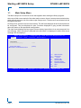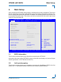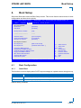
1
» User Guide « CP6002 uEFI BIOS Doc. ID: 1039-1612, Rev. 2.0 October 24, 2012 If it’s embedded, it’s Kontron. Preface CP6002 uEFI BIOS Revision History Publication Title: CP6002 uEFI BIOS uEFI BIOS User Guide Doc. ID: 1039-1612 Rev. Brief Description of Changes Date of Issue 1.0 Initial issue based on the uEFI BIOS version R13 11-Aug-2010 2.0 General update based on the uEFI BIOS version R21 24-Oct-2012 Imprint Kontron Europe GmbH may be contacted via the following: MAILING ADDRESS TELEPHONE AND E-MAIL Kontron Europe GmbH +49 (0) 800-SALESKONTRON Sudetenstraße 7 [email protected] D - 87600 Kaufbeuren Germany For further information about other Kontron products, please visit our Internet website: www.kontron.com. Disclaimer Copyright © 2010-2012 Kontron AG. All rights reserved. All data is for information purposes only and not guaranteed for legal purposes. Information has been carefully checked and is believed to be accurate; however, no responsibility is assumed for inaccuracies. Kontron and the Kontron logo and all other trademarks or registered trademarks are the property of their respective owners and are recognized. Specifications are subject to change without notice. Page ii ID 1039-1612, Rev. 2.0 CP6002 uEFI BIOS Preface Table of Contents Revision History .........................................................................................................ii Imprint ........................................................................................................................ii Disclaimer ..................................................................................................................ii Table of Contents ...................................................................................................... iii 1. Starting uEFI BIOS Setup .............................................................3 1.1 Main Setup Menu ......................................................................................... 4 1.2 Navigation .................................................................................................... 5 2. Main Setup .....................................................................................9 2.1 BIOS Information .......................................................................................... 9 2.2 UnCore Information ...................................................................................... 9 2.3 Trusted Computing ..................................................................................... 10 2.3.1 TPM Configuration ............................................................................. 10 2.3.1.1 TPM Support ............................................................................. 10 2.3.1.2 Current TPM Status Information ................................................ 10 2.4 Serial Port Console Redirection ..................................................................11 2.4.1 COM0 .................................................................................................11 2.4.1.1 Console Redirection ...................................................................11 2.4.1.2 Console Redirection Settings .....................................................11 2.4.2 COM1 .................................................................................................11 2.4.2.1 Console Redirection .................................................................. 12 2.4.2.2 Console Redirection Settings .................................................... 12 2.4.3 Serial Port for Out-of-Band Management/Windows Emergency Management Services (EMS) ............................................................ 12 2.4.3.1 Console Redirection .................................................................. 12 2.4.3.2 Console Redirection Settings .................................................... 13 2.4.4 Console Redirection Settings ............................................................ 15 2.4.4.1 Terminal Type ............................................................................ 15 2.4.4.2 Bits per second ......................................................................... 15 2.4.4.3 Data Bits .................................................................................... 16 2.4.4.4 Parity ......................................................................................... 16 ID 1039-1612, Rev. 2.0 Page iii Preface CP6002 uEFI BIOS 2.4.4.5 Stop Bits .....................................................................................16 2.4.4.6 Flow Control ...............................................................................16 2.4.4.7 Recorder Mode ..........................................................................16 2.4.4.8 Resolution 100x31 .....................................................................17 2.4.4.9 Legacy OS Redirection ..............................................................17 2.5 System Language .......................................................................................17 2.6 System Date ...............................................................................................17 2.7 System Time ...............................................................................................17 2.8 Access Level ...............................................................................................18 3. Chipset Setup ............................................................................. 21 3.1 South Bridge Configuration .........................................................................21 3.1.1 4. SATA Configuration ............................................................................22 3.1.1.1 SATA Mode Selection: IDE ........................................................23 3.1.1.2 SATA Mode Selection AHCI ......................................................25 3.1.1.3 SATA Mode Selection RAID ......................................................27 Boot Setup .................................................................................. 35 4.1 Boot Configuration ......................................................................................35 4.1.1 Quiet Boot ..........................................................................................35 4.1.2 uEFI Boot ...........................................................................................36 4.1.3 Bootup NumLock State ......................................................................36 4.1.4 CSM16 Module Version .....................................................................36 4.1.5 GateA20 Active ..................................................................................36 4.1.6 Option ROM Messages ......................................................................36 4.1.7 Interrupt 19 Capture ...........................................................................37 4.2 Boot Option Priorities ..................................................................................37 4.2.1 Boot Option #1..2 ...............................................................................37 4.2.2 Hard Drive/Network Device/CD/DVD ROM Drive/Floppy Drive/ BEV Device BBS Priorities .........................................................................37 4.2.3 Add New Boot Option .........................................................................38 4.2.4 Delete Boot Option .............................................................................38 Page iv ID 1039-1612, Rev. 2.0 CP6002 uEFI BIOS 5. Preface Security Setup .............................................................................41 5.1 Administrator Password ............................................................................. 42 5.2 User Password ........................................................................................... 42 5.3 HDD Security Configuration ....................................................................... 42 5.4 Remember the Password ........................................................................... 42 6. Save & Exit ...................................................................................45 6.1 Save Changes and Exit .............................................................................. 45 6.2 Discard Changes and Exit .......................................................................... 45 6.3 Save Changes and Reset .......................................................................... 45 6.4 Discard Changes and Reset ...................................................................... 46 6.5 Save Changes (Save Options) ................................................................... 46 6.6 Discard Changes (Save Options) ............................................................... 46 6.7 Restore Defaults (Save Options) ................................................................ 46 6.8 Save as User Defaults (Save Options) ....................................................... 46 6.9 Restore User Defaults (Save Options) ....................................................... 46 6.10 Boot Override ............................................................................................. 46 7. The uEFI Shell ..............................................................................49 7.1 Introduction, Basic Operation ..................................................................... 49 7.1.1 Shell Startup ...................................................................................... 49 7.2 Kontron Shell Commands .......................................................................... 50 7.2.1 kBiosRevision uEFI Shell Command ................................................. 51 7.2.2 kboardconfig uEFI Shell Command ................................................... 52 7.2.3 kboardinfo uEFI Shell Command ....................................................... 54 7.2.4 kboot uEFI Shell Command ............................................................... 56 7.2.5 kbootnsh uEFI Shell Command ......................................................... 57 7.2.6 kclearnvram uEFI Shell Command .................................................... 58 7.2.7 kclsp uEFI Shell Command ............................................................... 58 7.2.8 kipmi uEFI Shell Command ............................................................... 59 7.2.9 kmkramdisk uEFI Shell Command .................................................... 61 7.2.10 kpassword uEFI Shell Command ...................................................... 62 7.2.11 kresetconfig uEFI Shell Command .................................................... 63 ID 1039-1612, Rev. 2.0 Page v Preface CP6002 uEFI BIOS 7.2.12 kSettings uEFI Shell Command .........................................................64 7.2.13 kwdt uEFI Shell Command .................................................................65 7.3 uEFI Shell Scripting ....................................................................................66 8. 7.3.1 Startup Scripting .................................................................................66 7.3.2 Create a Startup Script .......................................................................66 7.3.3 Examples of Startup Scripts ...............................................................66 7.3.3.1 Automatic Booting from USB Memory Stick ..............................66 7.3.3.2 Switch On Clock Spreading Prior to Booting from Harddrive ....66 7.3.3.3 Execute Shell Script on Other Harddrive ...................................66 Updating the uEFI BIOS ............................................................. 69 8.1 BIOS Redundancy Strategy ........................................................................69 8.2 Updating Strategy .......................................................................................69 8.3 Fallback Mechanism ...................................................................................69 8.4 Flash Selection by IPMI Command ............................................................69 8.5 Flash Selection by DIP Switch ....................................................................70 8.6 Determining the Active Flash ......................................................................70 Page vi ID 1039-1612, Rev. 2.0 CP6002 uEFI BIOS Starting uEFI BIOS Setup Chapter 1 Starting uEFI BIOS Setup ID 1039-1612, Rev. 2.0 Page 1 Starting uEFI BIOS Setup CP6002 uEFI BIOS This page has been intentionally left blank. Page 2 ID 1039-1612, Rev. 2.0 CP6002 uEFI BIOS 1. Starting uEFI BIOS Setup Starting uEFI BIOS Setup The CP6002 is provided with a Kontron-customized, pre-installed and configured version of Aptio® (referred to as uEFI BIOS in this manual), AMI’s next generation BIOS firmware based on the Unified Extensible Firmware Interface (uEFI) specification and the Intel® Platform Innovation Framework for EFI. This uEFI BIOS provides a variety of new and enhanced functions specifically tailored to the hardware features of the CP6002. To take advantage of these functions, the uEFI BIOS comes with an uEFI Shell, which provides quick and easy access to the individual function settings for control or modification of the uEFI BIOS configuration, and a Setup program, which allows the accessing of various menus that provide functions or access to sub-menus with more specific functions of their own. The individual menus and the configurable functions are described in this guide. To start the uEFI BIOS Setup program, follow the steps below: 1. 2. 3. 4. Power on the board. Wait until the first characters appear on the screen (POST messages or splash screen). Press the <DEL> or <F2> key. If the uEFI BIOS is password-protected, a window such as the one below will appear: Enter Password Enter either the User password or the Administrator password (refer to Chapter 5, Security Setup, for further information), press <RETURN>, and proceed with step 5. 5. A Setup menu with the following token attributes will appear. The currently active menu and the currently active uEFI BIOS Setup item are highlighted in white. ID 1039-1612, Rev. 2.0 Page 3 Starting uEFI BIOS Setup 1.1 CP6002 uEFI BIOS Main Setup Menu The Main setup menu is the first screen that appears after starting the Setup program. At the top of this screen and all of the other major screens, there is a setup menu selection bar, which permits access to all of the other major setup menus. These menus are selected via the left-right arrow keys. All setup menu screens have two main frames. The left frame displays all the functions that can be configured. They are displayed in blue. Functions displayed in gray provide information about the status or the operational configuration. The right frame displays the key legend. Above the key legend there is an area reserved for a text message. When a function is selected in the left frame, it is displayed in white. Often a text message will accompany it. Aptio Setup Utility - Copyright (C) 2010 American Megatrends, Inc. Main C h i ps e t Bo ot Security Title (black) Read only field (grey) value Setup item (blue) [value] S a v e & E x it Pointer to a subordinate menu : Select Screen : Select Item Enter: +/-: F1: F2: F3 F4: ESC: Select Change Opt. General Help Previous Values Optimized Defaults Save Exit Ve r s i o n 2 . 0 1 . 1 2 0 4 . C o p y r i g h t ( C ) 2 0 1 0 A m e r i c a n M e g a t r e n d s , I n c . Page 4 ID 1039-1612, Rev. 2.0 CP6002 uEFI BIOS 1.2 Starting uEFI BIOS Setup Navigation The CP6002 uEFI BIOS setup program uses a hot key-based navigation system. A hot key legend is located in the right frame on most setup screens.The following table provides information concerning the usage of these hot keys. HOT KEY DESCRIPTION <F1> The <F1> key is used to invoke the General Help window. <F2> The <F2> key is used to restore the previous values. <F3> The <F3> key is used to load the optimized defaults. <F4> The <F4> key is used to save the current settings and exit the uEFI BIOS Setup. ← → Left/Right The Left and Right <Arrow> keys are used to select a major Setup screen. For example: Main Screen, Boot Screen, Security Screen, etc. ↑ ↓ Up/Down The Up and Down <Arrow> keys are used to select a Setup function or a sub-screen. + - Plus/Minus The Plus and Minus <Arrow> keys are used to change the field value of a particular Setup function, for example, system date and time. <ESC> The <ESC> key is used to exit a menu or the uEFI BIOS Setup. Pressing the <ESC> key in a sub-menu causes the next higher menu level to be displayed. When the <ESC> key is pressed in a major Setup menu, the uEFI BIOS Setup is terminated without saving any changes made. <Enter> The <Enter> key is used to execute a command or select a menu. ID 1039-1612, Rev. 2.0 Page 5 Starting uEFI BIOS Setup CP6002 uEFI BIOS This page has been intentionally left blank. Page 6 ID 1039-1612, Rev. 2.0 CP6002 uEFI BIOS Main Setup Chapter 21 Main Setup ID 1039-1612, Rev. 2.0 Page 7 Main Setup CP6002 uEFI BIOS This page has been intentionally left blank. Page 8 ID 1039-1612, Rev. 2.0 CP6002 uEFI BIOS 2. Main Setup Main Setup Upon entering the uEFI BIOS Setup program, the Main setup screen is displayed. This screen lists the main setup sub-screens and provides very basic system information as well as functions for setting the system time and date. In addition, the remaining major setup menus can be accessed from this screen. This screen can also be selected from any other major setup screen by using the Main tab. Aptio Setup Utility - Copyright (C) 2010 American Megatrends, Inc. Main C h ips e t Boot S e c u r it y Save & Exit BIOS Information BIOS Vendor Core Version Project Version Build Date American Megatrends 4.6.3.5 B3401 21.00 x64 05/08/2012 13:53:19 UnCore Information IGD VBIOS Version GMCH Version Total Memory 2117 18 4096 MB (DDR3: 1067 MHz) Memory Slot0 Memory Slot2 2048 MB (DDR3) 2048 MB (DDR3) Trusted Computing Serial Port Console Redirection : Select Screen : Select Item System Language [English] System Date System Time [Wed 08/22/2012] [19:33:43] Access Level Administrator Enter: +/-: F1: F2: F3: F4: ESC: Select Change Opt. General Help Previous Values Optimized Defaults Save Exit Ve r s i o n 2 . 0 1 . 1 2 0 4 . C o p y r i g h t ( C ) 2 0 1 0 A m e r i c a n M e g a t r e n d s , I n c . 2.1 BIOS Information This function provides display-only information concerning the uEFI BIOS. Information about the running uEFI BIOS version is reflected in the display-only function Project Version (parameter “21.00” indicates revision 21). 2.2 UnCore Information This function provides display-only information concerning the NorthBridge (GMCH die of the Intel® Core™ i7 processor) features, VBIOS revision and the system memory. ID 1039-1612, Rev. 2.0 Page 9 Main Setup 2.3 CP6002 uEFI BIOS Trusted Computing This screen provides functions for specifying the TPM configuration settings and TPM displaying status information. Aptio Setup Utility - Copyright (C) 2010 American Megatrends, Inc. Ma in Bo ot Security TPM Configuration TPM Support S a ve & E x i t [Enable] Current TPM Status Information NO TPM Hardware : Select Screen : Select Item Enter: +/-: F1: F2: F3 F4: ESC: Select Change Opt. General Help Previous Values Optimized Defaults Save Exit Ve r s i o n 2 . 0 1 . 1 2 0 4 . C o p y r i g h t ( C ) 2 0 1 0 A m e r i c a n M e g a t r e n d s , I n c . 2.3.1 TPM Configuration 2.3.1.1 TPM Support This function is used to provide the Trusted Platform Module (TPM) functionality to the OS. SETTING DESCRIPTION Disable Use this setting to disable the TPM support. If this setting is used, the TPM is not present for the OS, regardless whether the function TPM State is enabled or not. Enable Use this setting to enable the TPM support. Default setting: Enable 2.3.1.2 Current TPM Status Information This function provides display-only information concerning the Trusted Platform Module (TPM) operational status. Page 10 ID 1039-1612, Rev. 2.0 CP6002 uEFI BIOS 2.4 Main Setup Serial Port Console Redirection This screen provides information about functions for specifying the Serial Port Console Redirection configuration settings. Console redirection can be used to remotely operate system settings and the EFI console. Aptio Setup Utility - Copyright (C) 2010 American Megatrends, Inc. Main Boot S e c u r it y S a v e & E x it COM0 Console Redirection Console Redirection Settings [Enabled] COM1 Console Redirection Console Redirection Settings [Disabled] Serial Port for Out-of-Band Management/ Windows Emergency Management Services (EMS) Console Redirection [Disabled] Console Redirection Settings : Select Screen : Select Item Enter: +/-: F1: F2: F3 F4: ESC: Select Change Opt. General Help Previous Values Optimized Defaults Save Exit Ve r s i o n 2 . 0 1 . 1 2 0 4 . C o p y r i g h t ( C ) 2 0 1 0 A m e r i c a n M e g a t r e n d s , I n c . 2.4.1 COM0 The COM0 port (serial port 0) corresponds to the serial port on the front panel of the CP6002. 2.4.1.1 Console Redirection SETTING DESCRIPTION Disabled Use this setting to disable console redirection for the serial port 0. Enabled Use this setting to enable console redirection for the serial port 0. Default setting: Enabled 2.4.1.2 Console Redirection Settings For information about this function, refer to Chapter 2.4.4 in this manual. 2.4.2 COM1 The COM1 port (serial port 1) corresponds to the RS-422 (hardware designation COM2) serial port on the RIO connector (J3) of the CP6002. ID 1039-1612, Rev. 2.0 Page 11 Main Setup 2.4.2.1 CP6002 uEFI BIOS Console Redirection SETTING DESCRIPTION Disabled Use this setting to disable console redirection for the serial port 1. Enabled Use this setting to enable console redirection for the serial port 1. Default setting: Disabled 2.4.2.2 Console Redirection Settings For information about this function, refer to Chapter 2.4.4 in this manual. 2.4.3 Serial Port for Out-of-Band Management/Windows Emergency Management Services (EMS) The following functions control the presence and content of the ACPI serial port redirection table (SPCR). This table is mainly used by the Windows server variants to provide Windows Emergency Management Services (EMS). This functionality is totally independent from serial redirection of other console output. OoB Management or EMS makes it possible to control selected components of (Windows) servers, even when a server is not connected to the network or the network is not available. In short: EMS allows for remote management of a Windows Server OS through a serial port 2.4.3.1 Console Redirection SETTING DESCRIPTION Disabled Use this setting to prevent the system from adding the SPCR table to the ACPI tables. Enabled Use this setting to add the SPCR table to the ACPI tables. The OS can further use the information provided for serial redirection services. Default setting: Disabled Page 12 ID 1039-1612, Rev. 2.0 CP6002 uEFI BIOS 2.4.3.2 Main Setup Console Redirection Settings This screen provides information about functions for specifying the console redirection configuration settings for the Out-of-Band Management / Windows Emergency Management Services (EMS). Aptio Setup Utility - Copyright (C) 2010 American Megatrends, Inc. Main Boot S e c u r it y Out-of-Band MgmtPort Terminal Type Bits per second Flow Control Data Bits Parity Stop Bits S a v e & E x it [COM0] [VT-UTF8] [115200] [None] 8 None 1 : Select Screen : Select Item Enter: +/-: F1: F2: F3 F4: ESC: Select Change Opt. General Help Previous Values Optimized Defaults Save Exit Ve r s i o n 2 . 0 1 . 1 2 0 4 . C o p y r i g h t ( C ) 2 0 1 0 A m e r i c a n M e g a t r e n d s , I n c . 2.4.3.2.1 Out-of-Band Mgmt Port This function is used to select the serial port intended for use with Out-of-Band Management. This functionality is independent from serial redirection of other console output. SETTING DESCRIPTION COM0 Use this setting to specify that the serial port 0 is to be used with Out-of-Band Management. COM1 Use this setting to specify that the serial port 1 is to be used with Out-of-Band Management. Default setting: COM0 2.4.3.2.2 Terminal Type SETTING DESCRIPTION VT100 Use one of these settings to select the terminal type for out-of-band management. VT100+ VT-UTF8 ANSI Default setting: VT-UTF8 ID 1039-1612, Rev. 2.0 Page 13 Main Setup CP6002 uEFI BIOS 2.4.3.2.3 Bits per second SETTING DESCRIPTION 9600 Use one of these settings to select the baud rate of the serial port. 19200 57600 115200 Default setting: 115200 2.4.3.2.4 Flow Control SETTING DESCRIPTION None Use one of these settings to specify the type of flow control to be used for this serial port. Hardware RTS/CTS Software Xon/Xoff Default setting: None 2.4.3.2.5 Data Bits This is a display-only function providing information about the frame width for the Out-of-Band Management. 2.4.3.2.6 Parity This is a display-only function providing information about the parity for Out-of-Band Management. 2.4.3.2.7 Stop Bits This is a display-only function providing information about the number of stop bits for Out-ofBand Management. Page 14 ID 1039-1612, Rev. 2.0 CP6002 uEFI BIOS 2.4.4 Main Setup Console Redirection Settings This screen provides information about functions for specifying the Console Redirection configuration settings for the serial ports 0 and 1. Each serial port can be independently configured. Aptio Setup Utility - Copyright (C) 2010 American Megatrends, Inc. Main Boot S e c u r it y S a v e & E x it COM0 Console Redirection Settings Terminal Type Bits per second Data Bits Parity Stop Bits Flow Control Recorder Mode Resolution 100x31 Legacy OS Redirection [ANSI] [115200] [8] [None] [1] [None] [Disabled] [Disabled] [80x24] : Select Screen : Select Item Enter: +/-: F1: F2: F3 F4: ESC: Select Change Opt. General Help Previous Values Optimized Defaults Save Exit Ve r s i o n 2 . 0 1 . 1 2 0 4 . C o p y r i g h t ( C ) 2 0 1 0 A m e r i c a n M e g a t r e n d s , I n c . 2.4.4.1 Terminal Type SETTING DESCRIPTION VT100 Use one of these settings to select the terminal type to be emulated. VT100+ VT-UTF8 ANSI Default setting: ANSI 2.4.4.2 Bits per second SETTING DESCRIPTION 9600 Use one of these settings to select the baud rate of the serial port. 19200 57600 115200 Default setting: 115200 ID 1039-1612, Rev. 2.0 Page 15 Main Setup 2.4.4.3 CP6002 uEFI BIOS Data Bits SETTING DESCRIPTION 7 Use one of these settings to specify the number of data bits per frame. 8 Default setting: 8 2.4.4.4 Parity SETTING DESCRIPTION None Use one of these settings to select the parity for the serial port. Even Odd Mark Space Default setting: None 2.4.4.5 Stop Bits SETTING DESCRIPTION 1 Use one of these settings to specify the number of stop bits for the serial port. 2 Default setting: 1 2.4.4.6 Flow Control SETTING DESCRIPTION None Use one of these settings to specify the type of flow control to be used for this serial port. Hardware RTS/CTS Default setting: None 2.4.4.7 Recorder Mode Use this setting to specify whether display formatting characters are to be transmitted along with data or if only data is to be transmitted. SETTING DESCRIPTION Disabled Use this setting to specify normal terminal operation. Enabled Use this setting to specify that only text will be sent. Use this to capture terminal data Default setting: Disabled Page 16 ID 1039-1612, Rev. 2.0 CP6002 uEFI BIOS 2.4.4.8 Main Setup Resolution 100x31 SETTING DESCRIPTION Disabled Use this setting the disable extended terminal resolution. Enabled Use this setting the enable extended terminal resolution. Default setting: Disabled 2.4.4.9 Legacy OS Redirection SETTING DESCRIPTION 80x24 Use one of these settings to select the number of rows and columns for legacy OS redirection. 80x25 Default setting: 80x24 2.5 System Language SETTING DESCRIPTION English Use this function to select the system language. Currently, only English is supported. 2.6 System Date SETTING DESCRIPTION <WD MM/DD/YYYY> Use this function to change the system date. Select System Date using the Up and Down <Arrow> keys. Enter the new values through the keyboard. Use <TAB> to switch between date elements. 2.7 System Time SETTING DESCRIPTION <HH:MM:SS> Use this function to change the system time. Select System Time using the Up and Down <Arrow> keys. Enter the new values through the keyboard. Use <TAB> to switch between time elements. Note: The time is in 24-hour format. For example, 5:30 A.M. appears as 05:30:00, and 5:30 P.M. as 17:30:00. ID 1039-1612, Rev. 2.0 Page 17 Main Setup 2.8 CP6002 uEFI BIOS Access Level This function provides display-only information concerning the uEFI BIOS Setup accessibility for the current Setup session. Depending on the type of password protection used, one of the following settings is displayed: SETTING DESCRIPTION Administrator This setting indicates that read/write access to all setup options is available. User This setting indicates that only a limited subset of all setup options is modifiable. Note: Page 18 If no password is set, the access setup is Administrator. ID 1039-1612, Rev. 2.0 CP6002 uEFI BIOS Chipset Setup Chapter 31 Chipset Setup ID 1039-1612, Rev. 2.0 Page 19 Chipset Setup CP6002 uEFI BIOS This page has been intentionally left blank. Page 20 ID 1039-1612, Rev. 2.0 CP6002 uEFI BIOS 3. Chipset Setup Chipset Setup Select the Chipset tab to enter the Chipset Setup screen. This screen provides access to chipset configuration sub-screens Aptio Setup Utility - Copyright (C) 2010 American Megatrends, Inc. Main C h ips e t Boot S e c u r it y Save & Exit South Bridge Configuration : Select Screen : Select Item Enter: +/-: F1: F2: F3: F4: ESC: Select Change Opt. General Help Previous Values Optimized Defaults Save Exit Ve r s i o n 2 . 0 1 . 1 2 0 4 . C o p y r i g h t ( C ) 2 0 1 0 A m e r i c a n M e g a t r e n d s , I n c . 3.1 South Bridge Configuration This function provides access to the SouthBridge configuration settings. ID 1039-1612, Rev. 2.0 Page 21 Chipset Setup 3.1.1 CP6002 uEFI BIOS SATA Configuration This function provides access to the SATA Configuration settings. SATA operation depends on whether or not the SATA controller(s) is(are) enabled and, if enabled, which SATA mode is selected: IDE, AHCI or RAID. The following screens provide configuration possiblities depending on the enabling of the SATA controller(s) and the SATA mode selected. Aptio Setup Utility - Copyright (C) 2010 American Megatrends, Inc. Main C h i ps e t Bo ot Security S a v e & E x it SATA Configuration : Select Screen : Select Item Enter: +/-: F1: F2: F3: F4: ESC: Select Change Opt. General Help Previous Values Optimized Defaults Save Exit Ve r s i o n 2 . 0 1 . 1 2 0 4 . C o p y r i g h t ( C ) 2 0 1 0 A m e r i c a n M e g a t r e n d s , I n c . Page 22 ID 1039-1612, Rev. 2.0 CP6002 uEFI BIOS 3.1.1.1 Chipset Setup SATA Mode Selection: IDE This screen provides functions for enabling/disabling of the SATA controllers and for selecting the operational mode if enabled. The following screen indicates the functions available when the SATA controllers are enabled and the IDE mode is selected. Aptio Setup Utility - Copyright (C) 2010 American Megatrends, Inc. Main C h ips e t Boot S e c u r it y Save & Exit SATA Controller(s) SATA Mode Selection [Enabled] [IDE] Serial ATA Port 0 Software Preserve SATA Speed Limit Serial ATA Port 1 Software Preserve SATA Speed Limit Serial ATA Port 2 Software Preserve SATA Speed Limit Serial ATA Port 3 Software Preserve SATA Speed Limit Serial ATA Port 4 Software Preserve SATA Speed Limit Serial ATA Port 5 Software Preserve SATA Speed Limit Empty Unknown [No Limit] Empty Unknown [No Limit] Empty Unknown [No Limit] Empty Unknown [No Limit] INTEL SSDSA2SH (32.00) SUPPORTED [No Limit] Empty Unknown [No Limit] : Select Screen : Select Item Enter: +/-: F1: F2: F3: F4: ESC: Select Change Opt. General Help Previous Values Optimized Defaults Save Exit Ve r s i o n 2 . 0 1 . 1 2 0 4 . C o p y r i g h t ( C ) 2 0 1 0 A m e r i c a n M e g a t r e n d s , I n c . 3.1.1.1.1 SATA Controller(s) This function is used to enable or disable the onboard SATA controllers. SETTING DESCRIPTION Disabled Use this setting to disable the SATA controllers. Enabled Use this setting to enable the SATA controllers. Default setting: Enabled ID 1039-1612, Rev. 2.0 Page 23 Chipset Setup CP6002 uEFI BIOS 3.1.1.1.2 SATA Mode Selection This function is used to select the operational mode of the SATA controller(s) when enabled. SETTING DESCRIPTION IDE Use this setting to select IDE mode operation. AHCI Use this setting to select AHCI mode operation. RAID Use this setting to select RAID mode operation. Default setting: IDE 3.1.1.1.3 Serial ATA Ports 0 - 5 Displays an identifier string if a device is connected to the port indicated (0-5). 3.1.1.1.4 Software Preserve Ports 0 - 5 Indicates whether or not a connected device supports Software Setting Preservation (SSP). 3.1.1.1.5 SATA Speed Limit Ports 0 - 5 This function is used to limit the transfer speed of a SATA port. This function is available only when the SATA mode is set to IDE. SETTING DESCRIPTION No Limit Use this setting for no transfer speed limit Gen1 Use this setting to restrict port to Generation 1 communication rate (1.5 Gb/s). Default setting: No Limit Page 24 ID 1039-1612, Rev. 2.0 CP6002 uEFI BIOS 3.1.1.2 Chipset Setup SATA Mode Selection AHCI This screen provides functions for enabling/disabling of the SATA controller and for selecting the operational mode if enabled. The following screen indicates the functions available when the SATA controller is enabled and the AHCI mode is selected. Aptio Setup Utility - Copyright (C) 2010 American Megatrends, Inc. Main C h ips e t Boot S e c u r it y Save & Exit SATA Controller(s) SATA Mode Selection [Enabled] [AHCI] Serial ATA Port 0 Software Preserve Serial ATA Port 1 Software Preserve Serial ATA Port 2 Software Preserve Hot Plug Serial ATA Port 3 Software Preserve Hot Plug Serial ATA Port 4 Software Preserve Hot Plug Serial ATA Port 5 Software Preserve Hot Plug Empty Unknown Empty Unknown Empty Unknown [Disabled] Empty Unknown [Disabled] INTEL SSDSA2SH (32.00) SUPPORTED [Disabled] Empty Unknown [Disabled] : Select Screen : Select Item Enter: +/-: F1: F2: F3: F4: ESC: Select Change Opt. General Help Previous Values Optimized Defaults Save Exit Ve r s i o n 2 . 0 1 . 1 2 0 4 . C o p y r i g h t ( C ) 2 0 1 0 A m e r i c a n M e g a t r e n d s , I n c . 3.1.1.2.1 SATA Controller(s) This function is used to enable or disable the onboard SATA controller. SETTING DESCRIPTION Disabled Use this setting to disable the SATA controller. Enabled Use this setting to enable the SATA controller. Default setting: Enabled ID 1039-1612, Rev. 2.0 Page 25 Chipset Setup CP6002 uEFI BIOS 3.1.1.2.2 SATA Mode Selection This function is used to select the operational mode of the SATA controller when it is enabled. SETTING DESCRIPTION IDE Use this setting to select IDE mode operation. AHCI Use this setting to select AHCI mode operation. RAID Use this setting to select RAID mode operation. Default setting: IDE 3.1.1.2.3 Serial ATA Ports 0 - 5 Displays an identifier string if a device is connected to the port indicated (0-5). 3.1.1.2.4 Software Preserve Ports 0 - 5 Indicates whether or not a connected device supports Software Setting Preservation (SSP). 3.1.1.2.5 Hot Plug Ports 2 - 5 This function is used to enable or disable hot plug. This function is available only when SATA mode is set to AHCI or RAID and only for SATA ports 2-5. SETTING DESCRIPTION Disabled Use this setting to disable the hot plug feature. Enabled Use this setting to enable the hot plug feature. Default setting: Disabled Page 26 ID 1039-1612, Rev. 2.0 CP6002 uEFI BIOS 3.1.1.3 Chipset Setup SATA Mode Selection RAID This screen provides functions for enabling/disabling of the SATA controllers and for selecting the operational mode if enabled. The following screen indicates the functions available when the SATA controller is enabled and the RAID mode is selected. Aptio Setup Utility - Copyright (C) 2010 American Megatrends, Inc. Main C h ips e t Boot S e c u r it y Save & Exit SATA Controller(s) [Enabled] SATA Mode Selection [RAID] Software Feature Mask Configuration Serial ATA Port 0 Software Preserve Serial ATA Port 1 Software Preserve Serial ATA Port 2 Software Preserve Hot Plug Serial ATA Port 3 Software Preserve Hot Plug Serial ATA Port 4 Software Preserve Hot Plug Serial ATA Port 5 Software Preserve Hot Plug Empty Unknown Empty Unknown Empty Unknown [Disabled] Empty Unknown [Disabled] INTEL SSDSA2SH (32.00) SUPPORTED [Disabled] Empty Unknown [Disabled] : Select Screen : Select Item Enter: +/-: F1: F2: F3: F4: ESC: Select Change Opt. General Help Previous Values Optimized Defaults Save Exit Ve r s i o n 2 . 0 1 . 1 2 0 4 . C o p y r i g h t ( C ) 2 0 1 0 A m e r i c a n M e g a t r e n d s , I n c . 3.1.1.3.1 SATA Controller(s) This function is used to enable or disable the onboard SATA controller. SETTING DESCRIPTION Disabled Use this setting to disable the SATA controller. Enabled Use this setting to enable the SATA controller. Default setting: Enabled ID 1039-1612, Rev. 2.0 Page 27 Chipset Setup CP6002 uEFI BIOS 3.1.1.3.2 SATA Mode Selection This function is used to select the operational mode of the SATA controller when it is enabled. SETTING DESCRIPTION IDE Use this setting to select IDE mode operation. AHCI Use this setting to select AHCI mode operation. RAID Use this setting to select RAID mode operation. Default setting: IDE 3.1.1.3.3 SATA RAID Software Feature Mask Configuration This screen provides functions for configuring various RAID parameters. Aptio Setup Utility - Copyright (C) 2010 American Megatrends, Inc. Main C h i ps e t RAID0 RAID1 RAID10 RAID5 Intel Rapid Recovery OROM UI and BANNER Intel Rapid Recovery HDD Unlock LED Locate IRRT Only on eSATA Bo ot Security S a v e & E x it [Enabled] [Enabled] [Enabled] [Enabled] [Enabled] [Enabled] [Enabled] [Enabled] [Enabled] [Disabled] : Select Screen : Select Item Enter: +/-: F1: F2: F3: F4: ESC: Select Change Opt. General Help Previous Values Optimized Defaults Save Exit Ve r s i o n 2 . 0 1 . 1 2 0 4 . C o p y r i g h t ( C ) 2 0 1 0 A m e r i c a n M e g a t r e n d s , I n c . Page 28 ID 1039-1612, Rev. 2.0 CP6002 uEFI BIOS 3.1.1.3.3.1 Chipset Setup RAID0 This function is used to enable or disable the RAID0 feature. SETTING DESCRIPTION Disabled Use this setting to disable RAID0 feature. Enabled Use this setting to enable RAID0 feature. Default setting: Enabled 3.1.1.3.3.2 RAID1 This function is used to enable or disable the RAID1 feature. SETTING DESCRIPTION Disabled Use this setting to disable RAID1 feature. Enabled Use this setting to enable RAID1 feature. Default setting: Enabled 3.1.1.3.3.3 RAID10 This function is used to enable or disable the RAID10 feature. SETTING DESCRIPTION Disabled Use this setting to disable RAID10 feature. Enabled Use this setting to enable RAID10 feature. Default setting: Enabled 3.1.1.3.3.4 RAID5 This function is used to enable or disable the RAID5 feature. SETTING DESCRIPTION Disabled Use this setting to disable RAID5 feature. Enabled Use this setting to enable RAID5 feature. Default setting: Enabled 3.1.1.3.3.5 Intel Rapid Recovery This function is used to enable or disable Intel Rapid Recovery Technology. SETTING DESCRIPTION Disabled Use this setting to disable Intel Rapid Recovery Technology. Enabled Use this setting to enable Intel Rapid Recovery Technology. Default setting: Enabled ID 1039-1612, Rev. 2.0 Page 29 Chipset Setup 3.1.1.3.3.6 CP6002 uEFI BIOS OROM UI and BANNER This function is used to display or hide RAID OptionROM graphical UI and information. SETTING DESCRIPTION Disabled Use this setting to hide RAID UI and information as long as RAID volumes are normal. Enabled Use this setting to display RAID UI and information. Default setting: Enabled 3.1.1.3.3.7 HDD Unlock This function is used to indicate that the HDD password unlock in the OS is enabled. SETTING DESCRIPTION Disabled Use this setting to indicate that the HDD password unlock in the OS is disabled. Enabled Use this setting to indicate that the HDD password unlock in the OS is enabled. Default setting: Enabled 3.1.1.3.3.8 LED Locate This function is used to indicate that the LED/SGPIO hardware is attached and the “ping to locate” feature is enabled on the OS. SETTING DESCRIPTION Disabled Use this setting to indicate that the LED/SGPIO hardware is attached and the “ping to locate” feature is disabled on the OS. Enabled Use this setting to indicate that the LED/SGPIO hardware is attached and the “ping to locate” feature is enabled on the OS. Default setting: Enabled 3.1.1.3.3.9 IRRT Only on eSATA This function is used to indicate that only Intel Rapid Recovery Technology (IRRT) volumes or any RAID volume can span internal and external SATA. SETTING DESCRIPTION Disabled Use this setting to allow that any RAID volume can span internal and external SATA. Enabled Use this setting to allow only IRRT volumes to span internal and external SATA. Default setting: Disabled Page 30 ID 1039-1612, Rev. 2.0 CP6002 uEFI BIOS Chipset Setup 3.1.1.3.4 Serial ATA Ports 0 - 5 Displays an identifier string if a device is connected to the port indicated (0-5). 3.1.1.3.5 Software Preserve Ports 0 - 5 Indicates whether or not a connected device supports Software Setting Preservation (SSP). 3.1.1.3.6 Hot Plug Ports 2 - 5 This function is used to enable or disable hot plug. This function is available only when SATA mode is set to AHCI or RAID and only for SATA ports 2-5. SETTING DESCRIPTION Disabled Use this setting to disable the hot plug feature. Enabled Use this setting to enable the hot plug feature. Default setting: Disabled ID 1039-1612, Rev. 2.0 Page 31 Chipset Setup CP6002 uEFI BIOS This page has been intentionally left blank. Page 32 ID 1039-1612, Rev. 2.0 CP6002 uEFI BIOS Boot Setup Chapter 41 Boot Setup ID 1039-1612, Rev. 2.0 Page 33 Boot Setup CP6002 uEFI BIOS This page has been intentionally left blank. Page 34 ID 1039-1612, Rev. 2.0 CP6002 uEFI BIOS 4. Boot Setup Boot Setup Select the Boot tab to enter the Boot Setup screen. This screen lists the sub-screens for boot configuration and boot device priority. Aptio Setup Utility - Copyright (C) 2010 American Megatrends, Inc. Main C h ips e t Boot S e c u r it y Save & Exit Boot Configuration Quiet Boot UEFI Boot [Disabled] [Enabled] Bootup NumLock State [Off] CSM16 Module Version 07.63 GateA20 Active Option ROM Messages Interrupt 19 Capture [Upon Request] [Force BIOS] [Disabled] Boot Option Priorities Boot Option #1 Boot Option #2 [Built-in EFI Shell] [SanDisk uSSD 5000 ...] Hard Drive BBS Priorities Network Device BBS Priorities CD/DVD ROM Drive BBS Priorities Floppy Drive BBS Priorities BEV Device BBS Priorities Add New Boot Option Delete Boot Option : Select Screen : Select Item Enter: +/-: F1: F2: F3 F4: ESC: Select Change Opt. General Help Previous Values Optimized Defaults Save Exit Ve r s i o n 2 . 0 1 . 1 2 0 4 . C o p y r i g h t ( C ) 2 0 1 0 A m e r i c a n M e g a t r e n d s , I n c . 4.1 Boot Configuration 4.1.1 Quiet Boot This function is used to display either POST output messages or a splash screen during boot-up. SETTING DESCRIPTION Disabled Use this setting to display POST output messages during boot-up. Enabled Use this setting to display a splash screen during boot-up. Default setting: Disabled ID 1039-1612, Rev. 2.0 Page 35 Boot Setup 4.1.2 CP6002 uEFI BIOS uEFI Boot This function is used to enable or disable uEFI boot from disks. SETTING DESCRIPTION Disabled Use this setting to prevent the system from booting native uEFI operating systems from disks. Enabled Use this setting to enable booting of native uEFI operating systems from disks, if present, and in boot order. Default setting: Enabled 4.1.3 Bootup NumLock State This function is used to set the state of the keyboard’s numlock function after POST. SETTING DESCRIPTION On Use this setting to switch on the keyboard’s numlock function after POST. Off Use this setting to switch off the keyboard’s numlock function after POST. Default setting: Off 4.1.4 CSM16 Module Version This function provides display-only information concerning the CSM Module and is intended for internal use only. 4.1.5 GateA20 Active This function is used to enable or disable GateA20. SETTING DESCRIPTION Upon Request Use this setting to disable GA20 in the uEFI BIOS. Always Use this setting to prevent the system from disabling GA20. Default setting: Upon Request 4.1.6 Option ROM Messages This function is used to control the messages of the loaded PCI option ROMs. SETTING DESCRIPTION Force BIOS Use this setting to force to a BIOS-compatible output. This will show the option ROM messages. Keep Current Use this setting to keep the current video mode. This will suppress option ROM messages. Option ROMs requiring interactive inputs may not work properly in this mode. Default setting: Force BIOS Page 36 ID 1039-1612, Rev. 2.0 CP6002 uEFI BIOS 4.1.7 Boot Setup Interrupt 19 Capture This function is used to specify if legacy PCI option ROMs are allowed to capture software interrupt 19h. SETTING DESCRIPTION Disabled Use this setting to prevent legacy PCI option ROMs from capturing software interrupt 19h. Enabled Use this setting to allow legacy PCI option ROMs to capture software interrupt 19h. Default setting: Disabled 4.2 Boot Option Priorities 4.2.1 Boot Option #1..2 These functions are used to form the boot order and are dynamically generated. They represent either a legacy BBS (BIOS Boot Specification) class of devices or a native EFI boot entry. Press Return on each option to select the BBS class / EFI boot entry desired. 4.2.2 Hard Drive/Network Device/CD/DVD ROM Drive/Floppy Drive/ BEV Device BBS Priorities These functions lead to sub-menus that allow configuring the boot order for a specific device class. These options are only visible if at least one device for this class is present. These functions are dynamically generated. ID 1039-1612, Rev. 2.0 Page 37 Boot Setup 4.2.3 CP6002 uEFI BIOS Add New Boot Option This function is used to create a native uEFI boot option. When selected a sub-menu appears with functions for creating a new boot option. Select each function as appropriate, then either fillout the pop-up menu by typing in the requested information or select an appropriate item within the pop-up menu. After completing all entries, select “Create” to generate a new boot option. These options are only visible if at least one USB device is present. Aptio Setup Utility - Copyright (C) 2010 American Megatrends, Inc. Ma in Bo ot Security S a ve & E x i t Add New Boot Option Add boot option Select Filesystem Path for boot option Create [PCI(1D|0)\USB (1,...] : Select Screen : Select Item Enter: +/-: F1: F2: F3 F4: Select Change Opt. General Help Previous Values Optimized Defaults Save ESC: Exit Ve r s i o n 2 . 0 1 . 1 2 0 4 . C o p y r i g h t ( C ) 2 0 1 0 A m e r i c a n M e g a t r e n d s , I n c . Add boot option: Enter a descriptive name for the OS for the new boot option (e.g. RedHat Linux) Select Filesystem: Select the corresponding filesystem of the OS for the new boot option from the list presented Path for boot option: Enter the path where the OS is located for the new boot option Create: 4.2.4 Select “Create” to generate the new boot option using the information provided above Delete Boot Option This function is used to delete a native uEFI boot option. Note: Page 38 Do not delete the “Built-in EFI Shell” boot option as this would remove the uEFI Shell from the boot order. In case the uEFI Shell got removed, use “Save & Exit” / “Boot Override” / “Built-in EFI Shell” to recover. ID 1039-1612, Rev. 2.0 CP6002 uEFI BIOS Security Setup Chapter 51 Security Setup ID 1039-1612, Rev. 2.0 Page 39 Security Setup CP6002 uEFI BIOS This page has been intentionally left blank. Page 40 ID 1039-1612, Rev. 2.0 CP6002 uEFI BIOS 5. Security Setup Security Setup Select the Security tab to enter the Security Setup screen. This screen provides information about the passwords and functions for specifying the security settings. Aptio Setup Utility - Copyright (C) 2010 American Megatrends, Inc. Main C h ips e t Boot S e c u r it y Save & Exit Password Description If ONLY the Administrator’s password is set, then this only limits access to Setup and is only asked for when entering Setup. If ONLY the User’s password is set, then this is a power on password and must be entered to boot or enter Setup. In Setup the User will have Administrator rights. Administrator Password User Password HDD Security Configur HDD 0:ST9120822SB : Select Screen : Select Item Enter: +/-: F1: F2: F3 F4: ESC: Select Change Opt. General Help Previous Values Optimized Defaults Save Exit Ve r s i o n 2 . 0 1 . 1 2 0 4 . C o p y r i g h t ( C ) 2 0 1 0 A m e r i c a n M e g a t r e n d s , I n c . The following modes of security are provided:. SETTING DESCRIPTION No password is set Booting the system as well as entering the Setup is unsecured. Only Administrator password is set Booting the system is unsecured. Only User password is set The password is required for booting the system as well as for entering the Setup menu. On every startup, the user will be asked for the password. Both User and Administrator passwords are set Booting the system as well as entering the Setup is secured. For entering the Setup, the Administrator password is required. For entering the Setup, a password is required. If the User password is entered here, security related Setup entries cannot be modified. Entering the Administrator password provides full access to all Setup entries. ID 1039-1612, Rev. 2.0 Page 41 Security Setup 5.1 CP6002 uEFI BIOS Administrator Password This function is used to set, change or delete the Administrator password. If there is already a password installed, the system asks for this first. To clear a password, simply enter nothing and acknowledge by pressing Return. To set a password, enter it twice and acknowledge by pressing Return. Note: The password is case sensitive. 5.2 User Password This function is used to set, change or delete the User password. If there is already a password installed, the system asks for this first. To clear a password, simply enter nothing and acknowledge by pressing Return. To set a password, enter it twice and acknowledge by pressing Return. Note: The password is case sensitive. 5.3 HDD Security Configuration This function is only available if a HDD/SSD is detected which supports this function. Warning! Before using this function, contact Kontron’s Technical Support for assistance. Failure to comply with the instruction above may result in an irreparable disk lockout. 5.4 Remember the Password It is highly recommended to keep a record of all passwords in a safe place. Forgotten passwords may lead to being completely locked out of the system. If the system cannot be booted because neither the User password nor the Administrator password are known, refer to Chapter 4.1 in the CP6002 User Guide for information about clearing the uEFI BIOS settings, or contact Kontron for further assistance. Note: The harddisk User password cannot be cleared using the above method. Page 42 ID 1039-1612, Rev. 2.0 CP6002 uEFI BIOS Save & Exit Chapter 61 Save & Exit ID 1039-1612, Rev. 2.0 Page 43 Save & Exit CP6002 uEFI BIOS This page has been intentionally left blank. Page 44 ID 1039-1612, Rev. 2.0 CP6002 uEFI BIOS 6. Save & Exit Save & Exit Select the Save & Exit tab to enter the Save & Exit menu screen. This screen provides functions for handling changes made to the uEFI BIOS settings and the exiting of the Setup program. Aptio Setup Utility - Copyright (C) 2010 American Megatrends, Inc. Main C h ips e t Boot S e c u r it y Save & Exit Save Changes and Exit Discard Changes and Exit Save Changes and Reset Discard Changes and Reset Save Options Save Changes Discard Changes : Select Screen : Select Item Restore Defaults Save as User Defaults Restore User Defaults Boot Override Built-in EFI Shell SanDisk uSSD 5000 0.1 Enter: +/-: F1: F2: F3 F4: ESC: Select Change Opt. General Help Previous Values Optimized Defaults Save Exit Ve r s i o n 2 . 0 1 . 1 2 0 4 . C o p y r i g h t ( C ) 2 0 1 0 A m e r i c a n M e g a t r e n d s , I n c . 6.1 Save Changes and Exit This function is used to save all changes made within the Setup to flash. This function continues the boot process as long as no option was altered that requires a reboot. Note: The Setup will ask for confirmation prior to executing this command. 6.2 Discard Changes and Exit This function is used to discard all changes made within the Setup. This function continues the boot process. Note: The Setup will ask for confirmation prior to executing this command. 6.3 Save Changes and Reset This function is used to save all changes made within the Setup to flash. This function performs a reboot afterwards. Note: The Setup will ask for confirmation prior to executing this command. ID 1039-1612, Rev. 2.0 Page 45 Save & Exit 6.4 CP6002 uEFI BIOS Discard Changes and Reset This function is used to discard all changes made within the Setup. This function performs a reboot afterwards. Note: The Setup will ask for confirmation prior to executing this command. 6.5 Save Changes (Save Options) This function is used to save all changes made within the Setup to flash. This function returns to Setup. Note: The Setup will ask for confirmation prior to executing this command. 6.6 Discard Changes (Save Options) This function is used to discard all changes made within the Setup. This function returns to Setup. Note: The Setup will ask for confirmation prior to executing this command. 6.7 Restore Defaults (Save Options) This function is used to restore all tokens to factory default. Note: The Setup will ask for confirmation prior to executing this command. 6.8 Save as User Defaults (Save Options) This function is used to save all current settings as user default. The current setup state can later be restored using Restore User Defaults. Note: The Setup will ask for confirmation prior to executing this command. 6.9 Restore User Defaults (Save Options) This function is used to restore all tokens to settings previously stored by Save as User Defaults. Note: The Setup will ask for confirmation prior to executing this command. 6.10 Boot Override This group of functions includes a list of tokens, each of them corresponding to one device within the boot order. Select a drive to immediately boot that device regardless of the current boot order. If booting to EFI Shell this way, an exit from the shell returns to Setup. Page 46 ID 1039-1612, Rev. 2.0 CP6002 uEFI BIOS The uEFI Shell Chapter 71 The uEFI Shell ID 1039-1612, Rev. 2.0 Page 47 The uEFI Shell CP6002 uEFI BIOS This page has been intentionally left blank. Page 48 ID 1039-1612, Rev. 2.0 CP6002 uEFI BIOS 7. The uEFI Shell The uEFI Shell The Kontron uEFI BIOS features a built-in and enhanced version of the uEFI Shell. For a detailed description of the available standard shell scripting refer to the EFI Shell User’s Guide. For a detailed description of the available standard shell commands, refer to the Shell Command Manual 1.0. Both documents can be downloaded from the EFI and Framework Open Source Community website: http://sourceforge.net/projects/efi-shell/files/documents/. Please note that not all shell commands described in the Shell Command Manual 1.0 are provided by the Kontron uEFI BIOS. 7.1 Introduction, Basic Operation The uEFI Shell forms an entry into the uEFI boot order and is the first boot option by default. It is simply started by putting the uEFI Shell first in boot and running the board as usual. 7.1.1 Shell Startup If the shell is executed, it displays its signon message followed by a list of detected devices. The output produced by the device mapping table can vary depending on the board’s configuration. EFI Shell version 2.00 [4.631] Current running mode 1.1.2 Device mapping table fs0 :Removable HardDisk - Alias hd33b0b0b blk0 Acpi(PNP0A03,0)/Pci(1D|7)/Usb(1, 0)/Usb(1, 0)/HD(Part1,Sig17731773) fs1 :Removable BlockDevice - Alias f33b0c0 blk1 Acpi(PNP0A03,0)/Pci(1D|7)/Usb(1, 0)/Usb(2, 0) blk0 :Removable HardDisk - Alias hd33b0b0b fs0 Acpi(PNP0A03,0)/Pci(1D|7)/Usb(1, 0)/Usb(1, 0)/HD(Part1,Sig17731773) blk1 :Removable BlockDevice - Alias f33b0c0 fs1 Acpi(PNP0A03,0)/Pci(1D|7)/Usb(1, 0)/Usb(2, 0) blk2 :HardDisk - Alias (null) Acpi(PNP0A03,0)/Pci(1F|2)/Ata(Primary,Master)/HD(Part1,SigC811D18D) blk3 :BlockDevice - Alias (null) Acpi(PNP0A03,0)/Pci(1F|2)/Ata(Primary,Master) blk4 :Removable BlockDevice - Alias (null) Acpi(PNP0A03,0)/Pci(1D|7)/Usb(1, 0)/Usb(1, 0) Press the ESC key within 5 seconds to skip startup.nsh, and any other key to continue. If the ESC key is pressed before the 5-second timeout has elapsed, the shell prompt is shown: Shell> ID 1039-1612, Rev. 2.0 Page 49 The uEFI Shell 7.2 CP6002 uEFI BIOS Kontron Shell Commands The Kontron uEFI implementation provides the following additional commands related to the specific HW features of the Kontron system: • • • • • • • • • • • • • kBiosRevision kboardconfig kboardinfo kboot kbootnsh kclearnvram kclsp kipmi kmkramdisk kpassword kresetconfig kSettings kwdt The following chapters provide information concerning these Kontron-specific commands. The command response values indicated can vary depending on the board’s configuration. Where applicable, in the following command descriptions, the default settings are indicated in brackets. Page 50 ID 1039-1612, Rev. 2.0 CP6002 uEFI BIOS 7.2.1 The uEFI Shell kBiosRevision uEFI Shell Command kBiosRevision FUNCTION: SYNTAX: Get BIOS revision kBiosRevision [-?|-lt|-eq|-gt] <number> where: ? -lt -eq -gt <number> DESCRIPTION: USAGE: Show online help Check if current BIOS revision is less than <number> Check if current BIOS revision is equal to <number> Check if current BIOS revision is greater than <number> revision number to be used The kBiosRevision command can be used to display the current BIOS revision. In scripting environments it can be used to perform checks against a specified BIOS revision number. Note that the command name “kBiosRevision” is case sensitive. Display current BIOS revision: COMMAND / RESPONSE: Shell> kBiosRevision BIOS revision: 21 Check if current BIOS revision is equal to R21 (used within EFI shell script): kBiosRevision -eq 21 if not %lasterror% == 0 then echo "NOT R21, need to update" goto _update else "EFI R21 found" endif ID 1039-1612, Rev. 2.0 Page 51 The uEFI Shell 7.2.2 CP6002 uEFI BIOS kboardconfig uEFI Shell Command kboardconfig FUNCTION: SYNTAX: Configure the non-volatile board settings kboardconfig kboardconfig [-?|<device>|<setting>] where: ? <device> <setting> DESCRIPTION: Show online help Specify device from list Select configuration type The kboardconfig command enables the PXE feature or sets the front/ rear I/O configuration of the dedicated device. Note that many command settings are case sensitive. USAGE: Show all possible configurations COMMAND / RESPONSE: Shell> kboardconfig Control nonvolatile board settings Example: kboardconfig pxe: Select PXE boot network adapter ([disabled] all front_a front_b rear_a rear_b) StorageOrom: Launch Storage PCI OpROM (disabled [enabled]) HyperThreading: Enable Hyper Threading technology (disabled [enabled]) CpuTurbo: Enable CPU turbo mode technology (disabled [enabled]) PrimaryDisplay: Select primary display device ([auto] igd peg pci) vga: VGA Port Configuration ( auto [front] rear disabled ) SataMode: Determines how SATA controller(s) operate ([ide] ahci raid wr_prot_sata: Onboard Sata flash write protection ([disabled] enabled) NOTE: CONTACT KONTRON BEFORE USING THIS FUNCTION wr_prot_eeprom: System EEprom write protection ([disabled] enabled) wr_prot_spi: EFI spi flash write protection ([disabled] enabled) CStates: Enable CPU C-States ( disabled [enabled] ) C1eState: Enable CPU C1e-State ( disabled [enabled] ) C3State: Enable CPU C3-State ( [disabled] enabled ) C6State: Enable CPU C6-State ( [disabled] enabled ) PciCfgDelay: Set Delay for PCI CFG Cycle ( [disabled] 1s 2s 3s 4s 5s ) VgaInterrupt: Enable VGA interrupt generation ( [disabled] enabled ) Show allowed settings e.g. for “PrimaryDisplay”: Shell> kboardconfig PrimaryDisplay PrimaryDisplay: Select primary display device PrimaryDisplay == auto Allowed options: auto, igd, peg, pci Page 52 ID 1039-1612, Rev. 2.0 CP6002 uEFI BIOS The uEFI Shell kboardconfig SETTINGS: pxe: Select PXE boot network adapter disabled: No PXE boot available [all]: Try all Ethernet devices round robin for PXE boot front_a: Try only front port a for PXE boot front_b: Try only front port b for PXE boot rear_a: Try only rear port a for PXE boot rear_b: Try only rear port b for PXE boot Note: front_a corresponds to GbE A and front_b corresponds to GbE B on the front panel of the CP6002. StorageOrom: Launch Storage PCI Option ROMs disabled: Do not launch storage PCI option ROMs. This includes the onboard RAID option ROM. [enabled]: Launch storage option ROMs, if present HyperThreading: [Enable]/Disable Hyper-Threading Technology. If this option is changed, a power cycle is required for it to take effect. CpuTurbo: [Enable]/Disable CPU Turbo Boost Technology PrimaryDisplay: Select primary display device [auto]: Automatically detect primary display device igd: Use internal graphics, if enabled peg: Try to use video on the PCIe graphics port, if present pci: Try to use video on the PCI(e) bus first VGA Port configuration Automatically detect devices. HDMI/DVI on Rear I/O takes precedence over Front VGA if devices are connected to both front and rear [front]: Try to use Front-VGA if available. rear: Try to use device connected to Rear I/O if available disabled: Disable graphic output vga: auto: SataMode: Determines how SATA controllers operate [ide]: SATA ports operate as two IDE controllers ahci: SATA ports operate as one 6-port AHCI controller raid: SATA ports operate as one 6-port RAID controller wr_prot_sata: Onboard SATA flash write protection [disabled]: Do not write protect the onboard SATA flash enabled: The onboard SATA flash is write-protected after POST. NOTE: CONTACT KONTRON BEFORE USING THIS FUNCTION ID 1039-1612, Rev. 2.0 Page 53 The uEFI Shell CP6002 uEFI BIOS kboardconfig SETTINGS wr_prot_eeprom: System EEPROM write protection [disabled]: Do not write protect the system EEPROM enabled: System EEPROM is write-protected after POST wr_prot_spi: EFI SPI flash write protection [disabled]: Do not write protect the EFI SPI flash enabled: The EFI SPI flash is write-protected after POST CStates: Enable/Disable all CPU CStates ( [enabled] ) C1eState: Enable/Disable CPU C1eState ( [enabled] ) C3State: Enable/Disable CPU C3State ( [disabled] ) C6State: Enable/Disable CPU C6State ( [disabled] ) PciCfgDelay: Set Delay for PCI Configuration Cycle [disabled]: No delay for PCI Configuration Cycle 1s, 2s, 3s, 4s or 5s: 1 to 5 seconds delay possible VgaInterrupt: Enable/Disable VGA interrupt generation (assertion of IGD interrupt signal) ( [disabled] ) 7.2.3 kboardinfo uEFI Shell Command kboardinfo FUNCTION: SYNTAX: DESCRIPTION: Page 54 Show board identification data kboardinfo The kboardinfo command shows a summary of board-specific identification data. It is especially useful for support queries because it contains this data in a concentrated form. ID 1039-1612, Rev. 2.0 CP6002 uEFI BIOS The uEFI Shell kboardinfo USAGE: Show board identification data COMMAND / RESPONSE: Shell> kboardinfo KOMaOEMF rev.: Board ID: Hardware rev.: Logic rev.: Boot flash: In system slot: Geographic address: Material number: Hardware index: Serial number: EFI article name: EFI material number: EFI index: NorthBridge rev.: SouthBridge rev.: Microcode: CPU ID: CPU Branding: RIO Module REMARKS: KOMaOEMF rev.: Board ID: Hardware rev.: Logic rev.: Boot flash: In system slot: Geographic Address: Material number: Hardware index: Serial number: EFI article name: EFI material number: EFI index: NorthBridge rev.: SouthBridge rev.: Microcode: CPU ID: CPU Branding: RIO Module: ID 1039-1612, Rev. 2.0 3 0xB340 0x1 0x2 Boot flash 0 Yes 3 <nnnn-nnnn> <nn> <nnnnnnnnn> SK-EFI-B3401 <nnnn-nnnn> 21, standard 0x18 0x6 0x2 0x20655 Intel(R)Core(TM) i7 CPU E 610 @ 2.53 GHz 0x010 Revision of KOMaOEMF protocol Kontron board identification value Hardware revision of this board Logic revision of this board Current boot flash: either “Boot flash 0” or “Boot flash 1” Yes / no Geographic address of the cPCI backplane slot the board is currently plugged into Kontron hardware reference number Kontron hardware index This board’s unique serial number Kontron uEFI reference name Kontron uEFI reference number Version of this uEFI BIOS Chip revision of the NorthBridge (GMCH die of the Intel® Core™ i7 processor) Chip revision of the SouthBridge (Intel ® QM57) Currently loaded microcode CPUID CPU identification string RIO identification string Page 55 The uEFI Shell 7.2.4 CP6002 uEFI BIOS kboot uEFI Shell Command kboot FUNCTION: SYNTAX: Boot a legacy OS Not to be used for uEFI BootLoaders! kboot [-?|-d|-p|-p <path>|-n <name>|-t <type>] where: -? -d -p <path> -n <name> -t <type> DESCRIPTION: USAGE: Show online help Boot default order Specify the path to the device to boot from Specify the device name to boot from Specify the device type to boot from Available types are: floppy harddrive cdrom network usb-floppy usb-harddrive usb-cdrom The kboot command boots a legacy OS. Boot device can be selected in a very flexible way. If the requested device is not present, boot returns to shell. The kboot command cannot boot native uEFI operating systems. But since these are bootable from shell by calling their bootloader, this is not necessary either. If a requested device is present but not bootable, uEFI continues to boot with the next bootable device in the boot order. Show all connected devices and select boot devices in various ways: COMMAND / RESPONSE: Shell> kboot _____BBS_TABLE_____ 00001 usb-harddrive "SanDisk Extreme 0001" Device path: Acpi(PNP0A03,0)/Pci(1A|0)/Usb(1, 0)/Usb(1, 0) 00002 usb-harddrive "JetFlashTS64GSSD18C3" Device path: Acpi(PNP0A03,0)/Pci(1D|0)/Usb(1, 0)/Usb(4, 0) 00000 harddrive "P0: HTS541040G9SA00 " Device path: Acpi(PNP0A03,0)/Pci(1F|2)/? Boot from device containing the string "SanDisk": Shell> kboot -n SanDisk Boot from first device found that is of type harddrive: Shell> kboot -t harddrive Boot from device using the path to the device: Shell> kboot -p "Acpi(PNP0A03,0)/Pci(1D|0)/Usb(1, 0)/ Usb(4, 0)" Page 56 ID 1039-1612, Rev. 2.0 CP6002 uEFI BIOS 7.2.5 The uEFI Shell kbootnsh uEFI Shell Command kbootnsh FUNCTION: SYNTAX: Manage the startup script stored in the flash kbootnsh [-b][-?|-g <filename>|-p <filename>|-d] where: -b -? -g <filename> -p <filename> -d DESCRIPTION: USAGE: Display output page by page Show online help Store the current boot script to disk. If there is no physical disk drive present, the kmkramdisk command may be used. Store the shell script pointed to by filename to flash. Note: The shell script cannot be larger then 400 bytes. Delete the current startup script from flash. The kbootnsh command manages the flash stored startup script. If the shell is launched by the boot process, it executes a shell script stored in the flash. If the shell script terminates, the shell will continue the boot process. However, the shell script can of course contain any other boot command. Get current startup script to file named boot.nsh kbootnsh -g boot.nsh Store file named boot.nsh to flash: kbootnsh -p boot.nsh Delete startup script: kbootnsh -d ID 1039-1612, Rev. 2.0 Page 57 The uEFI Shell 7.2.6 CP6002 uEFI BIOS kclearnvram uEFI Shell Command kclearnvram FUNCTION: SYNTAX: Clear the NVRAM to restore the system’s default settings kclearnvram [-?|-q] where: -? -q DESCRIPTION: show help silent mode operation (for use of this command in shell scripts) Invoking the kclearnvram command clears the system NVRAM. Since all EFI settings are stored inside the NVRAM, the default settings are loaded afterwards. When invoked without an option, this command must be confirmed by pressing “c”. If invoked with the “-q” option, no confirmation is requested. 7.2.7 kclsp uEFI Shell Command kclsp FUNCTION: SYNTAX: Configure clock spreading kclsp [-?|-d|-e] where: -? -d -e DESCRIPTION: USAGE: show help disable clock spreading enable clock spreading The kclsp command enables or disables clock spreading on the onboard core clock generator. Clock spreading can be used to reduce system EMI. Get help: COMMAND / RESPONSE: Shell> kclsp -? Kontron Clock Spreading Configuration for ICS9LRS3187 -d [disable clock spreading] -e enable clock spreading This parameter is volatile, and at the next startup it is set to disable. Page 58 ID 1039-1612, Rev. 2.0 CP6002 uEFI BIOS 7.2.8 The uEFI Shell kipmi uEFI Shell Command kipmi FUNCTION: SYNTAX: Read or configure available Board Management Controller parameters kipmi [-?] [-b] [<option>[ <parameter>]] where: -? -b show online help (for kipmi or kipmi + option) display output page by page OPTIONS fru info ipmb irq mode net sel sensor raw rawsendmessage display FRU data show information about the device and firmware IPMB bus settings get / set KCS IRQ set IPMI controller mode display and change SOL network settings handle system event log shows sensor related information execute raw IPMI command execute rawSendMessage ipmi cmd PARAMETERS Most of the above options have their own unique set of parameters. Use the online help (“-?”) for more information concerning the available parameters. DESCRIPTION: USAGE: The kipmi command can read event logs or can set the Board Management Controller IRQ configuration. This shell application can also be used to issue raw IPMI commands to the Board Management Controller. Read or configure available Board Management Controller parameters: COMMAND / RESPONSE: Shell> kipmi -b fru 0 “kipmi fru” alone returns parameter info or status Clear all sel entries kipmi sel clear Display sel entry number 3 in hex kipmi sel raw 0x03 Execute raw command. Example: Get selftest results kipmi raw 0x06 0x00 0x04 ID 1039-1612, Rev. 2.0 Page 59 The uEFI Shell CP6002 uEFI BIOS kipmi USAGE: Change IRQ kipmi irq 10 Show IRQ configuration kipmi irq SETTINGS: fru [<FRU Device ID>]: Displays FRU data Options: FRU Device ID: Numeric FRU Device ID. 0 is assumed if FRU Device ID is omitted. 0 is the baseboard’s own FRU Device ID. info: Display IPMI firmware information ipmb: Displays IPMB bus settings ipmb dual-ported: Switch IPMB bus to dual-ported mode ipmb single-ported: Switch IPMB bus to single-ported mode irq <number>: Display/Set the IRQ number of the KCS interface Options: 0: KCS uses no IRQ 10: KCS uses IRQ 10 11: KCS uses IRQ 11 The board must be reset for the settings to apply. mode <mode>: Display/Set the IPMI controller operating mode Options: bmc: IPMI controller operates in BMC mode smc: IPMI controller operates in SMC mode net: Set Serial-over-LAN parameters sel: Display system event log sensor list|read: Show board sensor data Options: list: Display an overview of all available board sensors read: Display specific sensor data raw [<bytes> <...>]: Execute raw IPMI command Syntax: raw [NetFn] [LUN] [COMMAND] ... Execute rawSendMessage command: COMMAND / RESPONSE: Shell> kipmi rawsendmessage 0x20 0x00 0x06 0x00 0x01 “kipmi rawsendmessage” alone returns error message and help on available parameters Page 60 ID 1039-1612, Rev. 2.0 CP6002 uEFI BIOS 7.2.9 The uEFI Shell kmkramdisk uEFI Shell Command kmkramdisk FUNCTION: SYNTAX: Create RAMdisk drives kmkramdisk [-?|-s <size> <name>] where: -? show help -s <size> <name> create a RAMdisk of given size in Megabytes with the mount point name <name> DESCRIPTION: Creates a RAMdisk of variable size. Can be very useful to perform file operations when no real filesystem is connected to the system. Note: The RAMdisk loses its mount point name after all drives are remapped by the map -r command. The RAMdisk will then be enumerated as any other connected drive and gain a mount point name like “fs0”. This is not a bug of the kmkramdisk command but a normal function of the uEFI framework. USAGE: Create RAMdisk: COMMAND / RESPONSE: rd:\> kmkramdisk -s 5 myramdisk Device mapping table myramdisk :BlockDevice - Alias (null) VenMsg’(93B5F448-127A-4B29-B3065BE8AAC4826E) Success - Force file system to mount rd:\> myramdisk: myramdisk:\> echo testfile > testfile myramdisk:\> ls Directory of: myramdisk:\ 05/24/08 04:39a 1 File(s) 0 Dir(s) ID 1039-1612, Rev. 2.0 22 testfile 22 bytes Page 61 The uEFI Shell 7.2.10 CP6002 uEFI BIOS kpassword uEFI Shell Command kpassword FUNCTION: SYNTAX: Control EFI setup and shell passwords kpassword [[-u [-n <password>] [-o <password>]]| [-s [-n <password>] [-o <password>]]] where: -u -s Install or change user password Install or change superuser password Additional options for automated scripting -n <password> -o <password> DESCRIPTION: New password to be set Password to be overwritten if one is already set When used without option “-n” the password is cleared The kpassword command is used to determine the status of both passwords (set or not set) and to set or clear the EFI shell and setup passwords. Both user and superuser (Administrator) passwords can be controlled with this command. Call without options to get current password status If a password has been previously entered, it must be re-entered to validate the command (-o <old-password>). Entering an empty password clears the password. Note: Before invoking this command, users must be aware of the consequences of the usage of passwords. Refer to chapter 5 for further information before implementing passwords. USAGE: Set User password for EFI setup and shell COMMAND / RESPONSE: kpassword -u No password is installed! Enter new USER password --> Retype password --> Done. Set new superuser password via script COMMAND / RESPONSE: kpassword -s -n <password> Change user password via script COMMAND / RESPONSE: kpassword -u -o <password> -n <password> Page 62 ID 1039-1612, Rev. 2.0 CP6002 uEFI BIOS 7.2.11 The uEFI Shell kresetconfig uEFI Shell Command kresetconfig FUNCTION: SYNTAX: Control the board reset behavior kresetconfig [-?|<parameter>] where: -? <parameter> DESCRIPTION: USAGE: Show help pcislave [on|off] Controls if the board shall react on a PCI backplane reset if it is used as slave board in a peripheral slot. It has no effect if the board is located within a PCI master slot. Note: This parameter is volatile, and at the next startup it is set to off. The kresetconfig command controls the board’s reset behavior. Enable PCI backplane reset: COMMAND / RESPONSE: Shell> kresetconfig pcislave on Reset from system master is enabled Disable PCI backplane reset: COMMAND / RESPONSE: Shell> kresetconfig pcislave off Reset from system master is disabled ID 1039-1612, Rev. 2.0 Page 63 The uEFI Shell 7.2.12 CP6002 uEFI BIOS kSettings uEFI Shell Command kSettings FUNCTION: SYNTAX: Verify the validity of the setup settings kSettings [-?|-s|-c] [<file>] where: -? show help -s Save current setup settings to “file” -c Compare current setup settings to “file” <file> DESCRIPTION: “file” to be used for saving or comparison The kSettings command is used to create a binary file of the current setup settings. This file can later be used to check whether the settings have changed or not. To use this command a device with a FAT file system is required to be connected. Note that the command name “kSettings” is case sensitive. USAGE: Save current setup settings (assumes that FAT file system is mapped to fs0:) COMMAND / RESPONSE fs0:\> kSettings -s companyDefaults.bin Reading flash content... done Saving setup settings to file... done Check whether current setup settings differ from “file” COMMAND / RESPONSE fs0:\> kSettings -c companyDefaults.bin Reading flash content... done Setup settings and file match Page 64 ID 1039-1612, Rev. 2.0 CP6002 uEFI BIOS 7.2.13 The uEFI Shell kwdt uEFI Shell Command kwdt FUNCTION: SYNTAX: DESCRIPTION: USAGE: Configure the Kontron onboard Watchdog kwdt [-?|-t <timeindex>] where: -? Show help -t <timeindex> Configure the Watchdog with the time related to <timeindex> and activate it with reset routing The kwdt command allows to enable the Kontron onboard Watchdog with reset target before OS boot. This can be used to detect if the OS fails to boot and react by reset. The OS Watchdog driver is required for this functionality to operate. Get help: COMMAND / RESPONSE: Shell> kwdt -t [time] value 0 = value 1 = value 2 = value 3 = value 4 = value 5 = value 6 = value 7 = value 8 = value 9 = value 10 = value 11 = value 12 = value 13 = value 14 = value 15 = -? - set Timer 125ms 250ms 500ms 1s 2s 4s 8s 16s 32s 64s 128s 256s 512s 1024s 2048s 4096s Set Watchdog to 16 seconds and activate it COMMAND / RESPONSE (none): Shell> kwdt -t 7 Note: Because there is no application which triggers the Watchdog, the system will be reset after 16 seconds in this case. This command should be invoked from a script, followed by an operating system boot, and the OS then has to start triggering the Watchdog. ID 1039-1612, Rev. 2.0 Page 65 The uEFI Shell 7.3 uEFI Shell Scripting 7.3.1 Startup Scripting CP6002 uEFI BIOS If the ESC key is not pressed and the timeout is run out, either the Kontron flash-stored startup is executed, if present, or the uEFI specified startup.nsh script located under \efi\boot\ on any of the attached drives is executed. If none of the startup scripts is present, or the startup script terminates, the default boot order is continued. If the shell is started with no interaction, it tries to execute some startup scripts automatically. It searches for scripts in the following order: 1. Kontron flash-stored startup script 2. If there is no Kontron flash-stored startup script present, the uEFI specified startup.nsh script is used. This script must be located on any of the attached FAT formatted disk drives under \efi\boot\startup.nsh. If both startup scripts are absent, the shell terminates and the default boot order is continued. 7.3.2 Create a Startup Script Startup scripts can be created using the uEFI Shell built-in editor edit or under any OS with a plain text editor of your choice. To create a startup.nsh type shell script, simply save the script on any FAT-formatted drive attached to the system under \efi\boot\startup.nsh. To create a Kontron flash-stored startup script, the script is to be saved anywhere on a FATformatted drive attached to the system and stored to flash using the built-in uEFI Shell command kbootnsh. 7.3.3 Examples of Startup Scripts 7.3.3.1 Automatic Booting from USB Memory Stick Automatic booting is made from a USB memory stick, if present, otherwise the boot is made from the harddrive. kboot -t usb-harddrive kboot -t harddrive If neither a USB memory stick nor a harddrive is present, the boot order is continued. 7.3.3.2 Switch On Clock Spreading Prior to Booting from Harddrive kclsp -e kboot -t harddrive If no harddrive is present, the default order is continued. 7.3.3.3 Execute Shell Script on Other Harddrive This example executes the shell script named bootme.nsh located in the root of the first detected disc drive (fs0). shell> fs0: fs0:\> bootme.nsh Page 66 ID 1039-1612, Rev. 2.0 CP6002 uEFI BIOS Updating the uEFI BIOS Chapter 81 Updating the uEFI BIOS ID 1039-1612, Rev. 2.0 Page 67 Updating the uEFI BIOS CP6002 uEFI BIOS This page has been intentionally left blank. Page 68 ID 1039-1612, Rev. 2.0 CP6002 uEFI BIOS 8. Updating the uEFI BIOS Updating the uEFI BIOS BIOS updates are typically delivered as an update CD ISO image. This ISO image needs just to be burned to a CD and booted. Follow the menu for updating the uEFI BIOS. For further information refer to the update CD documentation. 8.1 BIOS Redundancy Strategy The CP6002 has two sets of EFI flash chips to form an EFI redundancy strategy. Basic idea behind that is to always have at least one working EFI available regardless if there have been any flashing errors or not. 8.2 Updating Strategy To always maintain at least one EFI flash correct, the update CD uses the following update procedure: 1. Switch to the second flash. Since the update CD always changes the flash chip prior to doing any updates, the uEFI BIOS that was used to actually boot the board and is therefore known to be good is preserved for backup. 2. Update the second flash. This flash is now selected as active boot flash. The update CD will not allow to flash both chips at a time. Flashing both chips would destroy the backup version and therefore break the redundancy. If you want to have the same BIOS version on both flash chips, then simply run the update CD twice. 8.3 Fallback Mechanism In case of one EFI being corrupted and therefore the board not starting up, the IPMI controller automatically switches to the other flash and resets the board. The board should now come up successfully from the other not corrupted image. The flashing procedure can now be restarted to restore the broken image. 8.4 Flash Selection by IPMI Command Usually the active flash is selected by the IPMI controller. The flash bank can be switched via an IPMI OEM command. This command is used by the update CD. See the IPMI manual for further information. ID 1039-1612, Rev. 2.0 Page 69 Updating the uEFI BIOS 8.5 CP6002 uEFI BIOS Flash Selection by DIP Switch On some cases it may be necessary to force the board to boot from the other flash without using the appropriate IPMI command to switch the flash chips. In this case, the onboard DIP switch SW1, switch 2, is used to toggle the active flash. Note that this switch does not “select” one flash chip. It toggles the currently active flash. Therefore, the IPMI controller will still switch the flashes by command or in case of the active flash is defective. Note that using this DIP switch does not change the way the update CD handles the update procedure. Refer to the CP6002 user guide for further information. 8.6 Determining the Active Flash Sometimes it may be necessary to check which flash is active. On the AMI Aptio-based uEFI BIOS, the information is available using the EFI shell command “kboardinfo”. For further information, refer to the “kboardinfo” section in the uEFI Shell chapter of this document. Page 70 ID 1039-1612, Rev. 2.0