1
VENT-FREE
OWNER'S
PROPANE
OPERATION
GAS HEATER
AND INSTALLATION
MANUAL
0 00010
Models: CGR18PT and CGR30PT
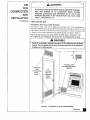
WARNING: If the_information in this manual _s not followed exactly,
may result causing property damage ' personal injury, or loss of life.
--
Do not store or use gasoline or other flammable
this or any other appliance.
--
WHAT TO DO IF YOU SMELL GAS
a fire or explosion
vapors and liquids in the vicinity of
• Do not try to light any appliance.
• Do not touch any electrical switch; do not use any phone in your building.
• Immediately call your gas supplier from a neighbor's
phone. Follow
supplier's instructions.
• If you cannot reach your gas supplier, call the fire department.
--
Installation and service must be performed
the gas supplier.
the gas
by a qualified installer, service agency, or
|
This is an unvented
gas-fired
heater.
installed. Prov sions for adequate
It uses air (oxygen)
combust on and ventilation
This appliance may be installed in an aftermarket*
prohibited by state or local codes.
from
the room in which
it is|
J
air must be provided.
manufactured
(mobile) home, where
not
"Affermarket: Completion of sale, not for purpose of resale, from the manufacturer.
This appliance is only for use with the type of gas
appliance is not convertible for use with other gases.
indicated
on the rating
plate.
This
Save this manualfor future reference.
CONTENTS
SECTION
PAGF
Safety Information
.......................................................................
Product Identification
4
Local Codes ................................................................................
4
Unpacking ...................................................................................
4
Product
4
Features ..........................................................................
Air For Combustion
And Ventilation ............................................
5
Installing To Wall ........................................................................
9
Installing Onto The Floor .............................................................
12
Connecting
13
To Gas Supply ..........................................................
Checking Gas Connections
...........................................................
Operating
H_ater And Lighting Instructions
Inspecting
Burner ........................................................................
14
.................................
16
18
Service Hints ...............................................................................
19
Clean_g
20
And Maintenance
Troubleshooting
Technical
..........................................................
...........................................................................
20
Service ........................................................................
24
Specifications
..............................................................................
24
Accessory ....................................................................................
24
lllustrated
25
Parts Breakdown
Warranty
SAFETY,
INFORMATION
2
..................................................................
and Parts List ...................................
and Repair Service.....:
.................................................
Back Cover
WARNINGS
IMPORTANT:
Read this owner's
manual
carefully
and completely
before trying to assemble, operate, or service this heater. Improper
use of this heater can cause serious injury or death from burns, fire,
explosion,
I
electrical
shock,
_
Carbon monoxide
and carbon
monoxide
poisoning.
DANGER
poisoning
may lead to deathl
]
Carbon Monoxide Poisoning: Early signs of carbon monoxide poisoning
resemble the flu, with headaches, dizziness, or nausea. If you have these signs, the
heater may not be working properly. Get fresh air at once! Have heater serviced.
Some people are more affected by c_rbon monoxide than others; These include
pregnant women, persons with heart or lung disease or anemia, those under the
influence of alcohol, and those at high altitudes.
Propane/LP
Gas: Propane/LP gas is odorless. An odor-making agent is added
to pmpane/l-,P gas. The odor helps you detect a pmpane/LP gasleak. However,
the odor addod to propane/LP gas can fade. Propane/LP gas may be present even
though no odor exists.
Make certain you read and understand
all warnings. Keep this manual
reference. It is your guide to safe and proper operation of this heater.
I_
Safety
Information
Continues
for
on next page
SAFETY
INFORMATION
Continued
WARNINGS
WARNING:
Continued
Any change to this beater or its controls can be dangerous.
1.
Use only propane/LP
2.
3.
Do not place propane supply tank(s) inside any structure. Locate propane/LP
supply tank(s) outdoors.
Tiffs heater shall not be installed in a bedroom or bathroom.
gas. Do not convert heater to use different fuel type.
4.
If you smellgas
• Shut off gas supply
• Do not try to light any appliance
• Do not touch any electrical
• Immediately
gas supplier's
5.
switch; do not use any phone in your building
call your gas supplier
from a neighbor's
instructions
• If you cannot reach your gas supplier,
Never install the heater
• in a recreational
phone. Follow the
caLl the fire department
vehicle
., where curtains, fumiture, clothing, or other flammable objects are less
than 36 inches from the front, top, or sides of the heater
• as a fireplace insert
• in high traffic areas
• in windy or drafty areas
6.
This heater needs fresh, outside air ventilation
to run properly. This heater
has an oxygen depletion sensor (ODS) pilot light safety system. The ODS
shuts down the heater if not enough fresh air is available. See Air for
Combustion and Ventilation, pages 5 through 8.
7.
8.
If heater shuts off, do not religfit until you provide fresh, outside air. If heater
keeps shutting off, have it serviced.
Do not run heater
• where flamrnable liquids or vapors are used or stored
• under dusty conditions
9.
Never place any objects on the heater.
10. Surface of heater becomes very hot when running heater. Keep children and
adults away from hot surface to avoid bums or clothing ignition. Heater will
remain hot for a time after shut-down. Allow surface to cool before touching.
11. Carefully
supervise young children when they are in same room with heater.
12. Make sure griU guard is in place before running heater.
13. Do not use heater if any part has been under water. Immediately call a
qualified service technician to inspect the room heater and to replace any part
of the control system and any gas control which has been under water.
14. Turn off heater and let cool before servicing.
should service and repair heater.
i5. Operating
heater above elevations
Only a qualified service person
"'
of 4,500 feet may cause pilot outage.
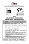
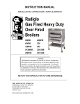
PRODUCT
IDENTIFICATION
Contml Knob
101111111111 Piozo, ,o
Burner (Infrared Plaques)
-_Pront Panel
/
Grill Guard
Safety Pilot System
Figure t. Vent-Free Propane/I.P
LOCAL CODES
Gas Thermostatic
Heater
Install and use heater with care. Follow all local codes. In the absence of local
codes, use the latest edition of National
as NFPA 54".
Fuel Gas Code ANSI Z223.1, also known
*Available from:
American
National
Standards
Institute, Inc.
1430 Broadway
New York, NY 10018
National
Fire Protection
Association,
Inc.
Batterymarch Park
Quincy, MA 02269
UNPACKING
1. Remove heater from cal'ton.
2. Remove all protective packaging applied to heater for shipment.
3. Check heater for any shipping damage. If heater is damaged, promptly inform
dealer where you bought heater.
PRODUCT
FEATURES
Safety Device
This heater has a pilot with an Oxygen Depletion Sensor Shutoff System (ODS).
The ODS/pilot is a required feature for vent-free room heaters. The ODS/pilot shuts
off the heater if there is not enough fresh air.
Plezo Ignition System
This heater has a piezo ignitor. This system requires no matches, batteries,
sources to light heater.
Thermostatic
|
or other
Heat Control
This heater has a thermostat sensing bulb and thermostat control. This results in
the greatest heater comfort. This can also result in lower gas bills.
AIR
FOR
COMBUSTION
AND
VENTILATION
WARNING
This heater must have fresh air for proper operation.
If not, poor
fuel combustion
could result. Read the following
instructions
to
insure proper fresh
in your home.
air for this and other
fuel-burning
appliances
Today's homes are built more energy efficient than ever. New materials, increased
insulauon, and new construction methods help reduCe heat loss in homes. Home
owners weather strip and caulk around windows and doors to keep the cold air out
and the warm air in. During heating months, home owners want their homes as
airtight as possible.
While it is good to make your home energy efficient, your home needs to breathe.
Fresh air muSt enter your home. All fue!-bummg appliances need fresh air for proper
combustion and ventilation•
Exhaustfans,
fireplaces,
clothes
dryers,
and fuel burning appliances
draw air from
the house to operate. You must provide adequate fresh air for these appliances, This
will iusure proper venting of vented fuel-burning appliances.
PROVIDING ADEQUATE VENTILATION
The following is exerpted from National Fuel Gas Code, NFPA 54/ANSI Z223.1,
•
....
Section
5.3, wAzr
for Combustion and Ventilation n .
All spaces in homes fall into one of the three following ventilation classifications:
1. Unusually Tight Contruction; 2. Unconfined Space; 3. Confined Space.
The information on pages 5 through 8 will help you classify your spa_:e and provide
adequate ventilation.
Unusually Tight Construction
The air that leaks around doors and windows may provide enough fresh air for
combustion and,ventilation. However, in buildings of unusually fight cousWactiou,
you must provide additional fresh air.
Unusually tight construction is defined as construction where:
a. walls and ceilings exposed to the outside atmosphere have a
continuous water vapor retarder with a rating of one perm or less
with openings gasketed or sealed and
b. weather stripping has been added on openahle windows and
doors and
c. caulking or sealants are applied to areas such as joints around
window and door frames, between sole plates and floors, between
wall-ceiling
joints, between
wall panels, at penetrations
for
plumbing, electrical, and gas lines, and at other openings.
If your home meets all of the three criteria above, you must provide
additional fresh air. See Ventilation Air From Outdoors, page 8. If your
home does not meet all of the three criteria above, continue reading.
Confined
This heater
Space and Unconfined
Space
shall not he iustalled in a toni'meal space
adequate ct)ulbustion
mid ventilation
The National Fuel Gas Code delines
air.
a conlincxl
unless provisions
space its a space
_e provided
whose volume
for
is less
than 50 cubic feet per 1,000 Btu per hour (4.8 m 3 per kw) ol lilt2 aggregate input rating
Continued
!
AIR
FOR
COMBUSTION
AND
VENTILATION
Continued
WARNING
If the area in which the heater may be operated is smaller
than that defined
as an unconfined
space,
provide
adequate
combustion
and ventilation
air by one of the
methods described
in the National Fuel Gas Code, ANSI
Z223.1, 1992 Section 5.3
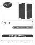
VENTILATION
Ventilation
AIR
Air From
Inside
Building
This fresh air would come from an adjoining unconfined
space. When ventilating to an
adjoining uncon fined space, you must prbvide two permanent openings: one _¢ithin 12" of the
ceiling
and one within
12" of the floor on the wall connecting
2, Figure 2). You can also remove
Follow the National
for Combustion
door into adjoining
(see options
l and
room (see option 3, Figure 2).
Fuel Gas Code, NFPA 54/ANSI Z223.1, Section 5.3, "Air
and Ventilation"
for required size of ventilation grills or ducts.
•
Rework
the two spaces
worksheet,
WARNING
adding thespace
of the adjoining
unconfined
space. The combined spaces must have enough fresh air to supply all
appliances in both spaces.
A
12" 1
/
Ventilation
Grills
Into Adjoining Room,
Ventilation
Grills
Option 2
into Adjoining
Room,
Option
1
\
/
Figure 2 - Ventilation
Air from Inside Building
Continued
AIR
FOR
COMBUSTION
AND
VENTILATION
Continued
VENTILATION
Ventilation
AIR (Continued)
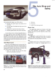
Air From Outdoors
Provide extra fresh air by using ventilation grills or ductS. You must provide two
•permanent openings: one within 12" of the ceiling and one within 12" of the floor.
Connect these items directly to the outdoors or spaces open to the outdoors. These spaces
include attics and crawl spaces. Follow the National Fuel Gas Code NFPA 54/ANSI
Z223.1. 1.992 $ecdort 5.3. Air for Combustion and Venlilqdon for required si.ze of
ventilation grills or ducts.
IMPORTANT: Do not provide openings for inlet or outlet air into attic if attic has a
thermostat.-conu'olled power vent. Heated air entering the attic will activate the power
venL
Outlet
Air
To Attic
Crawl
Space
To
I
Inlet
Air
I
I _
Inlet Air
Figure
m
_
3 - Ventilation
CrawlVentilatedspace
BE
Air from Outdoors
INSTALLING
TO WALL
A qualified
CHECK
service
person
NOTICE
must
install heater. Follow all local cedes.
t
GAS TYPE
Use only propane/LP gas. If your gas supply is not propane/LP, do not install
heater. Call dealer where you bought heater for proper type heater.
INSTALLATION
ITEMS
Before installing
heater, make sure you have the items listed below.
• external regulator (supplied by
installer, see page 13)
• piping (check local codes)
• sealant (resistant to propane gas)
• manual shutoff valve *
• ground joint union
• test gauge connection *
(see page 14)
• sediment trap
• tee joint
• pipe wrench
* An AGA design certified manual shutoff valve with I/8" NPT tap is an acceptable
alternative to test gauge connection.
Purchase the optional AGA design certified
manual shutoff valve from your dealer. See Accessory, page 24.
LOCATING
HEATER
Maintain the minimum clearances shown in Figure 4 (page 10). If you
WARNING
can, provide greater clearances
from floor, ceiling, and joining wall.
t
WARNING
Never install the heater
• in a bedroom or bathroom
• in a recreational vehicle
• where curtains,
furniture,
clothin g, or other flammable
less than 36 Inches from the front,
• as a fireplace insert
• in high traffic areas
• in windy or drafty areas
objects are
top, or sides of the heater
CAUTION
If you install the heater in a home garage
• heater pilot and burner must be at least 18 inches above floor
• locate heater where moving vehicle will not hit it
CAUTION
This heater creates
to wall surfaces
warm air currents.
next to heater.
These
Installing
currents move heat
heater next to vinyl or
cloth wall coverings or operating heater where impurities
(such as tobacco smoke) exist, may discolor
walls.
in the air
IMPORTANT.""Vent-free heaters add moisture to the air. Although this is beneficial,
in-
stalling heater in rooms without enough ventilation air may cause mildew to form from
to 9 much moisture, See AirforCornbu.vtionandVentilation, pages5_l_agh8.
Continued
INSTALLING
TO WALL
Continued
CLEARANCES
Provide adequate clearance around air openings.
Provide for an adequate combustion and ventilation air supply.
Accessibility provisions must be provided for servicing.
WALL
MOUNT
.The heater must be installed no less than 2" above the top surface of carpet_ng,
file, or other floor covering. When facingthe front of the heater, clearance from
combustibles must he a minimum of 13" from the left, 13" from the fight, 36"
from the top, and 2" from the bottom. The opening for combustion air located at
the bottom of the heater must not be obstructed. It must he free of obstacles.
Right side
din FROM WALLS
/
Front
Left side
FLOOR
HEATER
Figure
For convenience
4 - Mounting
Clearances
and efficiency, install heater
where there is easy access for operation,
•
inspection, and service
in coldest part of room
THERMOSTAT
SENSING
BULB
The thermostat sensing bulb has already been placed at the 1",ottomback of the
heater. It is not necessary to change its location for proper operation.
m
INSTALLING
WARNING
TO WALL
Continued
Maintain minimum clearances
shown
provide greater clearances from floor
INSTALLING
HEATER
in Figure 4. If you can,
and joining wall.
TO A WALL
1. Drill two 5/16" holes according to the dimension L shown in figure 5. Insert
two plastic wall anchors into holes. Tighten mounting screws into anchors.
Leave 1/8" space between screw head and anchor.
2. Hang the heater on the two mounting screws. Insert "U" hook into bottom of
cabinet. Mark anchor location through screw hole in "U" hook.
3. Remove heater from wall. Drill another 5/16" hole at marked location. Insert
last plastic wall anchor into hole.
4. Hang heater on wall and place "U" hook in place. Insert mounting screw
through "U" hook and into wall anchor. Tighten screw firmly.
5. Connect gas line to heater.
Note: AII the screws, anchors and hoo_. am furnished with the unit.
I
Mod. CGRI8PT: L= (15 114") 388 mm.
Mod. CGR30frI': L= (22 13/t6")580 mm.
m'_n._5
L
\
BACK OF HEATER
Left
Manual Shutoff
E
E
Figure
E
\
Front
"U"HOOK
Opening for combustion air
Valve
5 - Installing heater to a wall
INSTALLING
ONTO THE
FLOOR
INSTALLING
HEATER ONTO THE FLOOR
The heater includes
plastic legs for its direct installation onto the floor. To assure
a stability of the heater, the mounting
used to avoid side movements.
screws described in previous
page can be
As shown in Figure 6, the gas can be placed between the fieater and the floor.
If this appliance
is installed directly on carpeting, light-colored tile or other
combustible materia!, other than wood flooring, the appliance shall be installed
on a metal or a wood panel extending the full width and depth of the appliance.
This protective panel is not required a,s a fire-proof base. The protection is for
rugs that are extremely thick and light-colored tile which may discolor.
FIGURE 6 - Heater directly rested on the floor.
"-4
Itl
CONNECTING
TO GAS
SUPPLY
NOTICE
A qualified
service person
Follow all local codes.
must connect
heater to gas supply.
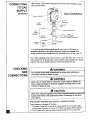
CAUTION
Never connect
heater requires
external
heater directly to the propane/LP
supply. This
an external
regulator
(not supplied).
Install the
regulator
between
the heater
The installer must supply an external
regulator.
and propane
supply.
The external regulator
will reduce
incoming gas pressure. You must i'educe incoming gas pressure to between 11 and
14 inches of water. If you do not reduce incoming gas pressure, heater regulator
damage could occur. Install external regulator with the vent pointing down as
shown in Figure 7. Pointing the vent down protects it from freezing rain or sleet.
Propane/LP
Supply Tank
Regulator
Extemal
Vent-Pointing
Down
Figure 7 - External Regulator With Vent Pointing Down
CAUTION
Use only new, black iron or steel pipe. Internally-tinned
copper
tubing may be used in certain areas. Check your local codes. Use
pipe of large enough diameter to allow proper gas volume to heater.
If pipe is too small, undue loss of pressure will occur.
Typical Pipe Diameters
CGRIgPT:
3/8" or greater
CGR30PT: I/'2" or greater
Installation must include a manual shutoff valve, union, and plugged 1/8" NPT
tap. Locate NPT tap within reach for test gauge hook up. NPT tap must be
upstream from heater (see Gas Connection, page 14).
Apply pipe joint sealant lightly to male threads. This will prevent excess sealant
from going into pipe. Excess sealant in pipe could result in clogged heater valves.
Use pipe joint
sealant
CAUTION
that is resistant
to liquid
petroleum
(LP) gas.
Install sediment trap in supply line as shown in Gas Conneclinn, page 14. l.,oc.ate
ediment trap where it is within reach for cle_tning. Locate sediment trap where
trapped matier is not likely to freeze, A sediment trap traps moisture and
contaminantS. This keeps them from going into heater controls. If sediment trap
is not installed or is instal.led wrong, heater may not run propedy.
lit
CONNECTING
TO GAS
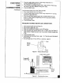
IMPORTANT: Hold pressure regulator with wrench when connecting it to gas
piping and/or fittings.
SUPPLY
Continued
Gas Connection
Pressure
Reg
NPT
Heater
Cabinet
Pipe Nipple
_round Joint
Manual Shutoff Valve "
coG_a_ien__.
Tee Joint_
From
Plug Tap
(1 1" W.C. to 14" W.C. Pressure)
Sediment
Trap
t 3" Minimum
* An AGA design certified manual slautoffvalve with 1/8'" NPT tap is an
acceptable alternative to test gauge connection. Purchase the optional AGA
design certified manual shutoff valve from your dealer. See Accessory, page 24.
Note: When installing
heater onto the floor, a male inlet elbow and a short nut
will substitute for the ground joint union so that the manual shutoff valve and the
sediment trap can be installed upstream without interfedng with floor.
CHECKING
GAS
CONNECTIONS
I
Test all gas piping and connections
servicing.
Correct
for leaks
WARNING
after installing
or
all leaks at once.
WARNING
Never use an open flame to check for a leak. Apply a mixture of
liquid soap and water to all joints. Bubbles forming show a leak.
Correct all leaks at once.
CAUTION
Make sure external
supply and heater.
ply, page 13.
PRESSURE
N
TESTING
regulator has been installed between propane/LP
See guidelines Under Connecting to Gas Sup-
GAS SUPPLY
PIPING
SYSTEM
Test Pressures In Excess Of 1/2 PSIG
1. Disconnect heater and its individual manual shutoff valve from gas supply
piping system. Pressures in excess of 1/2 PSIG will damage heater regulator.
2. Cap off open end of gas pipe where manual shutoff valve was connected.
CHECKING
GAS
CONNECTIONS
Contmued
3, Pressurize supply piping system by either using compressed
opening propane/LP supply tank valve.
4.
5.
air or
Check all joints of gas supply piping system. Apply mixture of liquid soap
and water to gas joints, Bubbles forming show a leak.
Correct all leaks at once.
Test Pressures Equal To or Less Than 1/2 PSIG
l.
Close manual shutoff valve (see Figure 8).
2. Pressurize supply piping system by either using compressed
propane/LP supply tank valve.
air or opening
3. Check all joints from propane supply tank to manual shutoff valve (see
Figure 9). Apply mixture of liquid soap and water to gas joints. Bubbles
forming show a leak.
4. Correct all leaks at once.
PRESSURE
TESTING
HEATER
GAS CONNECTIONS
1. Open manual shutoffvalve (see Figure 8).
2. "Open propane supply tank valve.
3. Make sum control knob of heater is in the OFF position.
4. Cl_ck all Dints from manual shutoff valve to control valve (see Figure 9).
Apply mixture of liquid soap and water to gas joints. Bubbles fomaing show
a leak.
5. Correct all leaks at once.
6. Light healer (see Operating
joints for leaks.
7.
Heater, page
Turn off healer (see To Turn OffGas
16). Checkthe
to Appliance,
restofthe
page _a)
Shutoff
Valve
Manual
z___
Open
-?
Closed
Figure 8 - Manual Shutoff Valve
Control Valve Location
IIIIIIIIIIIIIIIIIIIIIIIIIII
Propane/LP
Supply Tank
_
IIIIII
II
_Manual
o.
Figure
9
o
•
4
_{-_i
._o
•
Shutoff
Valve
__
i
- Checking
Gas Joints
internal
OPERATING
HEATER
AND LIGHTING
INSTRUCTIONS
[]
FOR YOUR
SAFETY
READ
BEFORE
LIGHTING
!-']
WARNING
If you do not follow
explosion
may result
injury or loss of life.
these
instructions
causing
exactly,
property
damage,
a fire or
personal
A.
This appliance has a pilot which must he lighted by hand.
the pilot, follow these instructions
exactly.
B.
BEFORE LIGHTING
smell all around the appliance area for gas. Be sure
to smell next to the floor because some gas is heavier than air and will
settle on the floor.
WHAT TO DO IF YOU SMELL
When lighting
GAS
• Do'not try to light any appliance.
• Do not touch any electric switch; do not use any phone in your building.
Immediately
call your gas supplier from a neighbor's
phone. Follow
the gas supplier's
instructions.
If you cannot
C.
reach your gas supplier,
Use only your hand to push in or turn
call the fire department.
the gas control
knob. Never
use
tools. If the knob will not push in or turn by hand, don't try to repair
call a qualified service technician or gas supplier. Force or attempted
repair may result in a fire or explosion.
Do
it,
Do not use this appliance if any part has been under water. Immediately
call a qualified service technician to inspect the appliance and to replace
any part of the control system and any gas control which has been under
water.
LIGHTING
INSTRUCTIONS
1. STOPI Read the safety information above.
2. Make sure manual shutoff valve is fully open.
3. Turn thermostat control knob clockwise (
to the "OFF" position.
/,
GAS CONTROL KNOB
SHOWN IN _OFF"
_,//'_
- (_0F
POSITION
4. Wait ten (10) minutes to clear any gas. Then smell for gas, including
near the floor. If you smell gas, STOPI Follow "B" in the safety
information above. If you don't smell gas, go to the next step.
5. Find pilot attached to the main burner which is located at bottom of
combustion chamber.
6. Turn knob on gas control counterclockwise
( _ ) to "Pilot" position.
OPERATING
HEATER
AND LIGHTING
INSTRUCTIONS
Continued
7. Depress
and hold down
the thermostat
control
knob,
While holding the control knob down, push the piezo ignitor button
repeatedly to light the pilot. Continue to hold the control knob in for
about 30 seconds after the pilot is lit. Release knob and it will pop
back up. Pilot should remain lit. If it goes out, repeat steps 3 through
7.
• If knob doe_; not pop up when released,
your service technician
or gas supplier.
stop and immediately
call
• If the pilot will not stay lit after several tries, turn the gas control
knob to the "OFF" position and call your service technician or gas
supplier.
8. Attentionl
Gas control has an INTERLOCK device. When the pilot is
initially !it and the safety magnet is energized (pilot stays "ON") the
INTERLOCK device becomes operative. If the gas control is turned to
the "OFF" position or gas flow to the appliance is shut off, the pilot
cannot be relighted until the safety magnet is de-energized
(approximately 60 seconds). There will be an audible "click" when the
safety magnet in the gas control is de-energized. Pilot can now be
elighted. Repeat steps 3 through 7.
9. Turn gas control Knob counterclockwise
level from "LO" to "HI".
( _
) to the desired heating
ELECTROOE
P_LOT
_._BURNER
LTHERMOCOUPLE
THERMOSTAT
When the hydraulic
OPERATION
thermostat
bulb "senses" the need for heat, the unit cycles
"ON" at a full input rate. The unit remains at this full input rate until the
hydraulic thermostat bulb is "satisfied". When this happens, the burner will shut
off with the pilot flame remaining lit.
Note: The burner modulates between "ON" and the pilot flame. When the
CGR 18PT is "ON" all three ceramic plaques will "glow". There will never be a
time when only one or two ceramic plaques are "glowing".
The "LO" and "HI" setting I_as temperature range of approximately
55 -_F to
90 _ F, respectively. This is the temperature at the hydraulic thermostat bulb, not
the room temperature. The owner is advised to determine the particular heat
setting that is desired for comfort, a.s heating requirements are different for every
owner.
Attention:
If no heat is desired, turn the gas control knob to the "Pilot" position
(not to the "LO" position).
im
OPERATING
HEATER
AND LIGHTING
TO TURN
SHUI-rlNG
OFF GAS TO APPLIANCE
OFF HEATER
1. Turn thermostat control knob clockwise ( _r ) to the "OFF"
position,
INSTRUCTIONS
Continued
SHUTTING
OFF BURNER
ONLY (Pilot stays lit)
1. Turn thermostat control knob clockwise ( _
MANUAL LIGHTING
l. Follow steps I through6
) to the "Pilot"
position,
PROCEDURE
under Lighting Instructions.
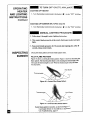
2. Whh control knob pressed in, strike match. Hold match to pilot until pilot
lights.
3. Keep control knob pressed in for 30 seconds after lighting pilot. After 30
seconds, release control knob.
INSPECTING
BURNER
Check pilot flame pattom and burner flame pattern often.
PILOT
FLAME
PATTERN
Figure 10 shows a correct pilot flame pattern. Figure l I shows an incorrect pilot
flame pattern. The incorrecX pilot flame is not touching the thermccouple, This
will cause the thermocouple to cool. When the thermocouple cools, the heater
vAll shut down.
Pilot Burner
Ther
Figure 10 - Correct Pilot Flame Pattern
Pilot Burner
Thermocouple
Figure 11 - Incorrect Pilot Flame Pattern
!
If pilot flame pattern is incorrect, as shown in Figure 11
• turn heater off (see To TurnOffGas to Appliance)
• see Troubleshoogng,
page 20
INSPECTING
BURNER
Continued
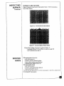
BURNER
FLAME
PATTERN
Figure 12 shows a correct burner flame pattern. Figure 13 shows an incorrect
burner flame pattern.
Figure
12 - Correct
Burner Flame Pattern
Figure t3 - Incorrect Burner Flame Pattern
If burner flame pattern is incorrect, as shown in Figure 13
• turn heater off (see To Turn OffGas to Appliance, page 18)
• see Troubleshooting,
page 2o
SERVICE
HINTS
When gas pressure
is too low
• pilot will not stay lit
• burner(s) will have delayed ignition
• heater will not produce specified heat
• propane/LP gas supply may l_e low
When gas quality is had
• pilot will not stay lit
• burner(s) will produce flames and soot
• heater will backfire when lit
You may feel your gas pressure is too low or gas quality is bad. If so, contact
local propane/LP gas supplier.
your
CLEANING
AND
MAINTENANCE
VVARNING
Turn off heater and let cool before
cleaning.
CAUTION
You must keep control
areas, burner, and circulating
air
passageways of heater clean. Inspect these areas of heater before
each use. Have heater inspected yearly by a qualified service
Heater may need more frequent cleaning due to excessive
lint from
carpeting,
ODS/PILOT
AND
bedding
BURNER
material,
etc.
ORIRCE
• Use a vacuum cleaner, pressurized
air, or small, soft bristled brash to clean.
CABINET
Air Passageways
• Use z_vacuum cleaner or pressurized
Exterior
• Use a soft cloth dampened
cabinet to remove dust.
with a mild soap and water mixture. Wipe the
WARNING
TROUBLESHOOTING
air to clean.
Turn off heater and let cool before servicing.
service person
should
service
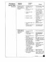
Note: All troubleshooting
items are listed in order of
Only a qualified
and repair heater.
CAUTION
operation.
Never use a wire, needle, or similar object to clean ODS/pilot.
can damage ODS/pllot unit.
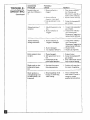
i OBSERVED
POSSIBLE
PROBLEM
CAUSE
REMEDY
When ignitor button is
pressed in, there is no
spark at ODS/pilot,
1. Ignitor electrode posifioned wrong.
2. Ignitor electrode broken.
3. Ignitor electrode not
connected to ignitor cable.
4. Ignitor cable pinched or
wet.
1. Replaceig_tor.
5. Broken ignitor cable.
6. Bad piezo ignitor.
7. Piezo ignitor nut _s loose.
m
This
2. Replace ignitor.
3. Reconnect ignitor cable.
4. Free ignitor cable if pinched
by any metal or tubing.
Keep ignitor cable dry.
5. Replace ignitor cable.
6. Replace control valve
(piezo is part of control
valve).
7. Tighten nut holding piezo
ignitor. Nut is located inside heater cabinet at top.
TROUBLE-
SHOOTING
Continued
OBSERVED
PROBLEM
POSSIBLE
CAUSE
When ignitor button is l. Gas supply turned off or
manual shutoff valve
pressed in, there is a
closed.
spark at ODS/Pilot but
no ignition.
2. Thermostat control knob
not pressed in.
3.
Aft in gas lines when
installed.
4. Depleted gas supply
5. ODS/pilot is clogged.
6. Gas regulator setting is not
correct.
7. Thermostat control knob is
not in pilot position.
ODS/pilot lights but
flame goes out when
control knob is
released.
REMEDY
I. Turn on gas supply or open
manual shutoff valve.
2. Press in thermostat conn-ol
knob while turning to
PILOT/IGN position.
3. Continue holding down
control knob. Repeat
igniting operation until air
is removed.
4. Contact local propane/LP
gas company.
5. Clean ODS/pilot (see
Cleaning and
Maintenance, page 20) or
replace ODS/pilot
assembly.
6. Replace gas regulator.
7. Tuna thermostat control
knob to pilot position,
l. Control knob not fully
pressed in.
2. Control knob not pressed
in long enough.
l. Press in conta'ol knob fully.
3. Manual shutoff valve not
3. Fully open manual shut-Off
valve.
__30
s_
fully open.
4. Thermocouple connection
loose at control valve.
4. Hand tighten until snug,
then tighten IN. turn more.
5. A) Contact local propane/Lt
gas company.
5. Pilot flame not touching
thermocouple, which
allows thermocouple to
B) Clean ODS/pilot (see
cool, causing pilot flame to
Cleaning and
go out_ This problem could
Maintenance, page 20) or
be caused by one or both of
replace ODS/pilot
the following:
assembly.
A) Low gas pressure
B) Dirty or partially
clogged ODS/pilot
6. Thermocouple damaged.
6. Replace thermocouple.
7. Control valve damaged.
7. Replace control valve.
8. Safety interlock system has 8. Wait one minute for safety
interlock s),stem to reset.
been triggered.
Repeat ignition operation.
Continued
TROUBLESHOOTING
Contmued
OBSERVED
PROBLEM
Burner(s) does not
light after ODS/pilot
lit.
POSSIBLE
CAUSE
is
1. Burner orifice(s)
clogged•
REMEDY
is
2. Burner orifice(s)
diameter is too small.
3. Inlet gas pressure is too
low
Delayed ignition of
burner(s)
1. Manifold pressure is too
low.
2. Bumerorifice(s)
is
clogged.
Burner backfiring
during combustion.
Burner plaque(s) does
not glow.
1. Burner orifice(s) is
clogged or damaged.
I. Clean burner orifice(s)
(see Cleaning and
Maintenance,
page 20 ) or
•replace burner orifice(s).
2. Replace burner orifice(s).
3. Contact local pmpane/LP
gas company,
1. Contact local propane/LP
gas company.
2. Clean burner orifice(s)
(see Cleaning and
Maintenance,
page 20 or
replace burner orifice(s).
2. Burner damaged.
3. Gas regulator defective.
1. Clean burner orifice(s)
(see Cleaning and
Maintenance, page 20) or
replace burner orifice(s).
2. Replace burner.
3. Replace gas regulator.
1. Plaque damaged,
2. Inlet gas pressure is too
low.
3. Control knob set be-
i. Replace burner.
2. Contact local propane/LP
gas company.
3. Turn control knob until it
tween looked positions,
locks at desired setting.
Slight smoke or odor
during initial operation
1. Residues from manufacturing processes
1. Problem will stop after a
few hours of operation.
"_
Heater produces a
clicklng/ticking noise
just after burner is lit
or shut off.
1. Metal expanding while
heating or contracting
while cooling.
1. This is common with
most heaters. If noise is
excessive, contact
qualified service person.
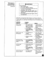
TROUBLESHOOTING
WARNING
If you smell gas
• Shut off gas supply.
Continued
• Do not try to light any appliance.
• Do not touch any electrical switch;
any phone in your building.
• Immediately
neighbor's
instructions.
do not use
call your gas supplier
from a
phone. Follow the gas supplier's
• If you cannot reach your gas supplier,
fire department.,
IMPORTANT:
Operating
call the
heater where impurities in air exist may create odors.
Cleaning supplies, paint, paint remover, cigarette smoke, cements and glues, new
ca.pet or textiles, etc., create fumes. These fumes may mix with combustion air and
create odors.
OBSERVED
PROBLEM
POSSIBLE
CAUSE-
Heater produces
unwanted odors.
1. Heater burning vapors
from paint, hair spray,
glues, etc. See IMPORTANT statemeat above
2. Low fuel supply
3. Gas leak. See Warning statement at top
of page.
Heater shuts off in use
(ODS operates).
Not enough fresh air is
available.
2. Low line pressure
I.
3. ODS/pilot is partially
clogged.
Gas odor even when
control knob is in OFF
REMEDY
1, Ventilate room. Stop
using odor causing
products while heater is
running.
2. Refill supply tank.
3. Locate and correct all
leaks (see Checking Gas
Cwmections. page14 ).
I. Open window and/or
door for ventilation.
2. Contact local propane/LP
gas company.
3. Clean ODS/pilot (see
Cleaning and Maintenance, page ZO).
1. Gas leak. See Warning statement
at top
of page.
2. Control valve defective.
1. Locate and correct all
leaks (see Checking Gas
Connections, page t4).
2. Replace control valve.
Gas odor during
combustion
1, Foreign matter between
control valve and
burner.
2. Gas leak. See Warning statement at top
of page.
1. Take apart gas tubing
and remove foreign
matter.
2. Locate and co.rrect all
leaks (see Checking Gas
Connections, page 14 ).
Moisture/condensation
noticed on windows
1. Not enough combostion/ventilation air.
1, Refer to Air for
Combustion and Venti-
position
lation requirements
(page 5)
TECHNICAL
SERVICE
You may have further questions about installation,
operation, or troubleshooting.
If so, contact DESA International's
Technical
Sev¢ice Department
at 1-800-3235190.
SPECIFICATIONS
CGR18PT
BTU
16,500
Type Gas
Ignition
Propane/LP
Piezo
CGR30PT
27,000
Only
Pressure Regulator Se_ng
10" W.C.
Inlet Gas Pressure (in. of water)
"
Maximum
14"
Minimum
11"
Dimensions,
Only
10" W.C.
14"
I1"
Inches (H x W x D)
H_r
Cartc,l
Weight (pounds)
Heater
Shipping
ACCESSORY
Propane/LP
Piezo
Purchase this heater accessory
24.5 x20x9
25.6 x 21.6 x 10.6
24.5 x27,5 x9
25.6 x 29.5 x 10.6
22
30
26
34
from your local dealer. If they cannot supply this
accessory, either contact your nearest Parts Central or call DESA International's
Parts Department at 1-800-972-7879
for referral information. You can also write
to the address listed on the back page of this manual.
MANUAL
SHUTOFF
VALVE - GA5010
Manual shutoff valve with 1/8"
NPT tap.
;OMFORT
BALTIMORE
GL(3W INFRA-RED
ELECTRIC
PLAQUE HEATEI_ PART CENTRALS
EAST COST ENERGY PRODUCTS
1348 O_1 Avenue
Hamd_ CT 06514
1-800-397-7553
707 Broadway
W Long Branch NJ 07764
¢2o3)248-_
1-8oo-7_
(90_ STO-SS09
Parts Oeoattment
PORTABLE
HEATERS pARTS
342 No _
Rd 400 Ea_
VaJl_tnuso IN 46383
AllSt=_
(ZlS)462-7441
1-800-362-6951
PartsO_ar_nent
FOUR FLAGS POWER
1115 St=t_ine Road
NUes MI 49120
(816) 684-2697
l
Pa_oW
PRODUCTS
DAYTONHARDWARE
PO Box 275
Noah DaytonStation
Dayton OH 45404
All States
_513) L:_'.._3721
OH 1-800762-3426
Parts Department
MASTERPARTS DISTRIBUTOR
11_,4Wibor, Ave N'W
Grand Rapids MI 49504
US 1-8(X)-44_1446
(616)791-0505
Fax:1-616-791-8270
partsDepartment
HALCO ENTERPRISES
WASHER EQUIP CO
1715 Main Street
KansasCity MO 64108
KS, MO, AR
(816)842-3911
PartsO_rtment
LAPORTES PARTS & SERVICES
206 Gaffer O6ve unit 21
West Chester PA 19382
US 1-8_0-368-08CG
(610) 430-7717
Parts_g_rtment
2444 N 5(h S_eet
Had,swaleSC 29550
(8O3)332-0191
PartsDepartment
DESA
REPAIR
PARTS LIST
INTERNATIONAL
MODELS CGR18PT
AND CGR30PT
2701 IndustrialDrive
P.O. Box 90004
Bowlfng Green, KY 421Q2-900,
®÷
W
ii
@
@
!
I
REPAIR
PARTS LIST
MODELS CGRI8PT
AND CGR30PT
Continued
Note." Use only original replacement
replaced under warranty.
Parts
Under
parts
This will protcc(
your warranty
for parts
Warranty
Cont_cl authorized dealer/tom
whom you purchased
original replacement
part(s), call DESA International's
800-323-5190
for i_formation.
this product
Technical
When contacting
have ready:
" yoIu-
coverage
your dealer or DESA
lnlemaliona],
If _hey ;u'e unable (o suppty
Service Department at 1-
name
- your address
• model number
of your heater
• how heater was malfunctioning
- type of gas used (propane or natural gas)
• purchase
Usually,
date
we will ask you to return the defective
Parts
Not Under
Contact
authorized
part to the factory.
Wa(ranty
dealers of this produc[.
If they can't supply
original
either contact your nearest Parts Central (see page 24) or call I)ESA
Department
at 1-800-972-7879
for referral information.
When
calling
model
DESA
International,
number
of your heater
the replacement
part number
replacement
International
part(s),
Parts
have ready
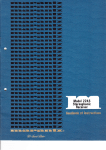
REPAIR
PARTS
MODELS
1
2
3
4
5
BY S0.000.048
BY 83.610.099
BY 13.310.512
BY 83.500.385
BY 13.650.056
BY S0,000.048
BY 83.610.099
BY 13.310.512
BY 83.500.385
BY 13.650.1056
Piezo ignitor
Controlvalve
Screw.
FRtlng
Nut M-18
6
7
8
g
10
BY 83.000.716
BY 83.000.562
BY 13.311.592
BY 80.100,057
BY 83.300.338
BY 83.000.716
BY 83.0&D.563
BY 13.311.592
BY 80.1Q0.058
BY 83,300.338
Tubingvalve - T connector
Tttoingvalve -p&X
Scow
Bum_
Odfice
11
12
13
14
:15
16
17
18
19
BY 83.O00.712
BY 83.000.713
BY 83.500.383
BY 75.300.043
BY 83.000.555
BY 83.500,385
BY 36.210.046
BY 13.490.075
BY 13.311.592
8Y 83.000.712
BY 83.0QO.713
BY 83.500.386
BY 75.300.043
BY 83.600.556
BY 83.500.385
BY 36.210.046
BY 13.490.075
BY 13.311.592
Tubipg.T cocme_o_- # 1 setting
TubingT o0nneclorT # 2 setting
T connector
Installationhardware
Tubingvalve - mgubtof
Regulato_kde(- adaplo¢
P.egulelor
Scow M 3.5
Screw
20
21
22
23
BY
BY
BY
BY
80.300.034
83.000.554
71.100.298
71.10G.297
BY 80,300.034
BY 83.000.557
BY 71.100.298
BY 71.100297
OOS assembly
TUbingT co_t_dor- # 3 se_ting
Front bcad,.e(
Rear brack_
24
25
26
27
28
29
30
31
32
33
34
BY
BY
BY
Ry
BY
BY
BY
BY
BY
BY
Ry
74.110.277
13.311.542
71.200.163
78.100.421
13.311.592
61.001.151
13.310.306
62`200.604
62.200.708
62.400.048
13.311.272
BY 74.110276
BY 13.311.542
BY 71.200.163
BY 78.100.421
BY 13.311.592
BY 61.001.151
BY 13.310.306
BY 62.200.605
BY 62.200.707
BY 6_400.04g
BY t 3.311.272
Salety guard
.Scn_
Frontal leg
Trim s_de
Screw
Valve bracket
Screw
Top heat shlekl
Bottomheal shield
Casbg
Screw
35
36
37
38
39
40
41
4?.
BY 71.200.160
BY 13.310.306
BY 62.100.526
BY 64.160.017
BY 2"2.130.680
BY 61.000.954
BY 71.200.160
BY 13.310.306
BY 62.100.525
BY 64.160.018
BY 22.130.680
BY 61.000.954
BY 83.(X)0.714
BY 83.000.715
Reaxleg
Screw
Fmcdaltefk3cto_
Frontalkame
Operatingand Instal_tion Manual
Regu_tor moun_g b_acket ..
Tub_g T c_ector - # 4 setlJng
TubingT conne<_o¢- # 5 setting
WARRANTY
INFORMATION
KEEP THIS WARRANTY
Model
Serial No.
Date Purchased
Always
specify model and serial numbers
when communicating
with the factory.
We reserve the right to amend these specifications
at any time without notice. The only warranty applicable
written warranty. We make no other warranty, expressed or implied.
COMFORT
GLOW
LIMITED WARRANTY
VENT-FREE
PROPANE
is our standard
GAS HEATERS
DESA International warrants this product and any parts thereof, to be free from def_ts in material and workmanship for one
year from the date of first purchase, provided that the product has been properly installed, operated, and maintained in
accordance with all applicable insmJ;ctions. To make a claim under this warranty, the bill of sales or proof of purchase must be
resented.
This warranty is extended only to the original retail l_rehaser. This wan'amy covers only the cost of parts anti an allowance for
labor required to restore this heater to proper operating condition. Warranty parts must be obtained through authorized dealers
of this product and/or DESA International who will provide original factory replacement parts. Failure to use original factory i
replacement parts voids tiffs warranty. The heater must be installed.by a qualified installer in accordance with all local codes
and instructions furnished with the unit.
This warranty does not apply to parts that are not in original condition because of normal wear and tear, or parts that fail or
become damaged as a result of misuse, accidents, lack of proper maintenance, alteration, tampering, contaminated fuels, or
defects caused by improper installation. Travel, transportation, and incidental costs associated with warranty repairs are not
reimbursable under this warranty anti are the responsibility of the owner.
To the.full extent allowed by the law of the jurisdiction that governs the
and all other expressed warranties and limits the duration of any
merchantability
and fitness for a particular purpose to one year from
liability is hereby limited to the purchase price of the product and DESA
whatsoever including indirect, incidental, or consequential damages.
Some states do not allow a limitation
consequential
you.
damages,
of how long an implied warranty
so the above limitation of implied warranties,
This warranty provides the original retail purchaser
please consult the applicable state laws.
For information
sale of the product; this express warranty excludes any
and all implied warranties, including warranties o_
the date of first purchase; and DESA International's
International shall not be liable for any other damages
about this wafTanty write:
lasts or an exclusion
or exclusion,
or limitation of incidental
or
or limitation of damages may not apply to !
with specific legal rights. For specific information
regarding
those fights,
DESA
INTERNATIONAL
2701 Industrial Drive
P.O. Box 90004
Bowling Green, KY 42102-9004
22.130.680
Rev.: a