1
UNIT 3
CERTIFICATION METER
Fiber Certification, cont.
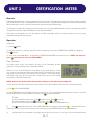
continue to step 5. Otherwise, highlight one of the user-defined standards and press F3 to edit the chosen user-defined standard.
CONFIGURE USER-DEFINED STANDARD
--Selected wavelengths for user-defined standards are denoted by asterisks. Up to two wavelengths may be selected.
NOTE: the same wavelength cannot be chosen twice.
4a)
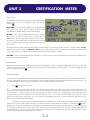
Highlight the first wavelength you wish to use, and press F2 to select.
4b)
Enter the attenuation characteristics (dB per kilometer) for 62.5 um multi-mode fiber, and press DONE to continue.
4c)
Enter the attenuation characteristics (dB per kilometer) for 50.0 um multi-mode fiber, and press DONE to continue.
4d)
Enter the attenuation characteristics (dB per kilometer) for inside plant single mode fiber, and press DONE to continue.
4e)
Enter the attenuation characteristics (dB per kilometer) for outside plant single mode fiber, and press DONE to continue.
4f)
Enter the loss per connector (dB), and press DONE to continue.
4g)
Enter the loss per splice (dB), and press DONE to continue.
4h)
Press F3 to select the second wavelength, if desired. Otherwise, press DONE to continue to Step 5.
4i)
Repeat steps 4b to 4g for the second wavelength. When completed, press DONE to continue.
5)
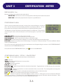
Press F2 to select the fiber standard.
6)
Press F2 to select the type of fiber you will be testing.
7)
Enter the length of the fiber you are testing. By default, the default length unit is METERS, but you may toggle length units
between METERS and FEET by pressing F2 . Press DONE to continue.
8)
Enter the number of connector pairs in the link you are testing and press DONE to continue. NOTE: the number of
connector pairs must be the same for both wavelengths.
9)
Enter the number of splices in the link you are testing and press DONE to continue. NOTE: the number of splices must be
the same for both wavelengths.
10)
You will be prompted to connect a light source for the chosen standard’s first wavelength. Press DONE once the appropriate
light source is attached.
NOTE: Make sure that the source is stable by allowing it sufficient time to warm up.
NOTE: In order to maintain the integrity of the reference you are setting, it is critical to leave the patch
cord connected to the light source. Disconnection of a patch cord from a light source will invalidate your
reference due to the inaccuracies in aligning the light source with the fiber core.
NOTE: In order to set an accurate reference for multi-mode fibers at 850 or 1300nm, the user must
wrap the reference patch cord around a mandrel, which is similar to a wooden dowel. The mandrel should be
approximately 1/2” in diameter, and the patch cord should be wrapped at least 5 times around the mandrel.
The mandrel is necessary for stripping off the optical energy that does not normally travel down the fiber link.
If this energy is not removed from the reference value, your fiber readings will
be too low, and may cause the link to appear as if it was failing.
11)
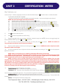
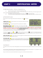
The settings you just entered will appear on the display.
SOURCE POWER (dBm) - actual power your light source is emitting.
100 Meters (dB) - attenuation value associated with the length and type of fiber you
entered. At times, an asterisk will appear here. This means that the length for the standard has been exceeded.
00 CON 00 SPL (dB) - attenuation value of the connectors and splices you entered.
REFERENCE PWR (dBm) - source power plus fiber attenuation plus connector and splice attenuation. This is the PASS / FAIL
threshold.
850nm - wavelength that the reference is being set for.
3-2
Test Equipment Depot - 800.517.8431 - 99 Washington Street Melrose, MA 02176
FAX 781.665.0780 - TestEquipmentDepot.com