1
Page 12
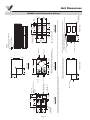
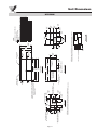
10.005"
[254]
LEFT VIEW
SUPPLY AIR
OPENING
EXHAUST AIR
OPENING
14.000"
[356]
CONTROL BOX
ACCESS
LOW VOLTAGE
TERMINAL STRIPS
SUPPLY AIR
EXHAUST AIR
LINE VOLTAGE IN
4.028"
[102]
A
5.859" [149]
C
5.125"
[130]
D
RETURN AIR
OUTDOOR AIR
FRONT VIEW
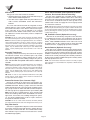
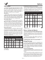
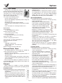
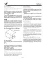
NOTE: For units with the reversed door option, interior
components will appear as a mirror image of the above diagram.
19.207"
[488]
34.000"
[864]
TOP VIEW
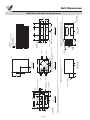
13.375"
[340]
B
B
A
B
7.705"
[196]
14.103"
[358]
RETURN AIR
OPENING
OUTDOOR AIR
OPENING
14.000"
[356]
23.500"
[597]
RIGHT VIEW
CONDENSATE DRAIN
4.000"
[102]
24.500"
[622]
2.750"
[70]
STRAP MOUNTING
LOCATION
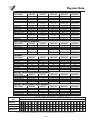
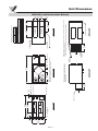
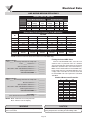
CONNECTION TABLE
CONNECTION SIZES
Line voltage in
14 gauge wire nut
Condensate drain fitting (2x)
3/4" mpt
HRV600i
ALUMINUM CORE
HM CORE
POLY CORE
PTS LBS Kg
PTS LBS Kg
PTS LBS Kg
17
38
18
19
40
41
A
A
A
25
26
27
B
12
12
11
B
B
C
24
C
25
C
25
52
55
56
33
D
D
D
15
15
16
34
35
70 TOTAL 159
72
67 TOTAL 155
TOTAL 148
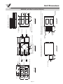
Direction of airflow
Center of gravity
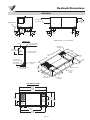
CONTROL PLATE
12.000"
[305]
FRONT VIEW
NOTE: A minimum of 12.000" [305] clearance from any
obstruction is required for removal of the control box.
HEAT RECOVERY CORE
ACCESS DOOR
15.000"
[381]
RIGHT VIEW
REVERSED
DOOR OPTION
NOTE: A minimum of 15.000" [381] clearance from any obstruction is required for
removal of heat recovery cores, fans, etc.
The access door can be removed from the cabinet with only 2.000" [51] of clearance.
8.000"
[203]
8.000"
[203]
6.500"
[165]
NOTE: This model has a damper located on the outdoor intake connection. This damper will close during a frost control cycle or when the unit is placed in the 'OFF' position with power maintained to the unit. This damper is not designed as a
backdraft damper and will remain open if power is disconnected from the unit for any reason.
REVERSED
DOOR OPTION
3.535" [90]
8.000"
[203]
4.000" [102]
8.000"
[203]
4.000"
[102]
28.005"
[711]
12.005"
[305]
A
NOTES:
Dimensions in [ ] are millimeters
HRV600i (with Exhaust Only Defrost)
Unit Dimensions