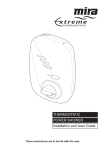
1
ic C t a I t AT s o T S m O r e R h T E M TH THERMOSTATIC POWER SHOWER Installation & User Guide THESE INSTRUCTIONS ARE TO BE LEFT WITH THE USER Contents Section Page 1 ...... Introduction ......................................................................................... 3 2 ...... Important Safety Information ............................................................. 4 3 ...... Pack Contents Checklist ...................................................................... 6 4 ...... Dimensions ......................................................................................... 7 5 ...... Specifications ...................................................................................... 8 6 ...... Installation Requirements: General ...................................................................................... 10 Electrical ................................................................................... 10 Plumbing ................................................................................... 11 Installation Diagrams ................................................................. 13 7 ...... Installation: Before You Start ........................................................................ 14 Configuring Inlet Supplies .......................................................... 15 Shower Installation .................................................................... 17 8 ...... Commissioning: General Commissioning ............................................................. 21 Adjustable Maximum Temperature Setting ................................ 22 Temperature Override Button - Disable ...................................... 24 9 ...... Operation ....................................................................................... 25 10 .... Fault Diagnosis: Fault Diagnosis – User Maintenance .......................................... 26 Fault Diagnosis – Installer Maintenance .................................... 27 11 .... Maintenance ...................................................................................... 30 12 .... Spare Parts ....................................................................................... 42 Guarantee, Customer Care Policy, and How to contact us ......... Back cover ii 2 Section 1 Introduction Thank you for purchasing a quality Mira product. To enjoy the full potential of your new shower, please take time to read this guide thoroughly, having done so, keep it handy for future reference. The Event XS Thermostatic is a surface mounted all-in-one thermostatic power shower. It is designed for use with a mains voltage electrical supply and gravity fed hot and cold water supplies. It features a built-in pump unit, thermostatic mixer assembly and separate power, flow and temperature controls. The thermostatic mixer assembly responds to changes in incoming water temperature to maintain the showering temperature selected. The temperature control is preset to give a maximum showering temperature of 41°C. However, it can be adjusted to suit installation or user requirements. An override button is fitted to the temperature control. This allows the user to override the maximum temperature and select higher showering temperatures. The button can be disabled, if required. The product is fitted with a 15 mm dual entry push-fit inlet manifold which allows pipe connections to the top, bottom or rear of the power shower. The inlet manifold also contains inlet filters and check valves. The shower control is supplied with Mira Logic power shower fittings. These fittings consist of an adjustable spray handset with four different spray actions (start, champagne, massage and economy), flexible hose, adjustable clamp bracket assembly, slide bar and supports, hose retaining ring and wall mounted soap dish. The fittings are available in a white/chrome or all white finish. The Mira Event XS T is not suitable for use in institutional/commercial applications. It must not be used with mains water pressure applications; for example, instantaneous electric heaters, instantaneous gas water heaters, unvented mains pressure systems, pumped shower systems and some combination-type storage systems. If you experience any difficulty with the installation or operation of your new shower control, please refer to "Fault Diagnosis" before contacting Kohler Mira Limited. Our telephone and fax numbers can be found on the back cover of this guide. 3 Section 21 Important Safety Information 1. Warning! 1.1. Products manufactured by us are safe and without risk provided they are installed, used and maintained in good working order in accordance with our instructions and recommendations. 1.2. THIS APPLIANCE MUST BE EARTHED. ENSURE SUPPLEMENTARY BONDING COMPLIES WITH THE "REQUIREMENTS FOR ELECTRICAL INSTALLATIONS". In accordance with the current edition of ‘The Plugs and Sockets etc. (Safety) Regulations' in force at the time of installation, the Mira Event XS T is intended to be permanently connected to the fixed electrical wiring of the mains system. 1.3. 1.4. 1.5. DO NOT connect the Mira Event XS T to a mains-fed water supply. Such a connection will damage the Mira Event XS T, and is not covered under the manufacturer’s guarantee. The Mira Event XS T must not be fitted where it may be exposed to freezing conditions. Make sure that any pipework that could become frozen is properly insulated. DO NOT operate the Mira Event XS T if it is frozen. Allow the Mira Event XS T to thaw before using again. 1.6. DO NOT operate the Mira Event XS T if water leaks from the unit, maintenance will be required before the Mira Event XS T can be safely used. 1.7. 1.8. DO NOT allow the Mira Event XS T to be run dry. DO NOT fit any form of outlet flow control. Only Mira recommended outlet fittings should be used. 1.9. There are no user serviceable components beneath the cover of the Mira Event XS T. Only a competent tradesperson should remove the cover. 1.10. If any of the following conditions occur, isolate the electricity and water supplies and refer to “To contact us”, on the back page of this guide. 1.10.1. If the cover is not correctly fitted and water has entered the case. 1.10.2. If the case is damaged. 1.10.3. If the Mira Event XS T begins to make an odd noise, smell or smoke. 1.10.4. If the Mira Event XS T shows signs of a distinct change in performance, indicating a need for maintenance. 1.10.5. If the Mira Event XS T is frozen. 1.11. Turn off the electrical and water supplies before removing the cover. The electricity must be turned off at the mains and, if applicable, the appropriate circuit fuse removed. 1.12. Mains connections are exposed when the cover is removed. 4 1.13. Moving parts are exposed when the cover is removed. 1.14. Make sure all electrical connections are tight, to prevent overheating. 1.15. Make a note of the layout of the wire runs and connections before removal. Make sure that they are replaced and connected as noted. 2. Caution! 2.1. Read all of these instructions and retain this guide for later use. 2.2. Pass on this guide in the event of change of ownership of the installation site. 2.3. Follow all warnings, cautions and instructions contained in this guide. 2.4. Follow all warnings, cautions and instructions contained on or inside the Mira Event XS T. The electrical installation must comply with the “Requirements for Electrical Installations” commonly referred to as the IEE Wiring Regulations, or any particular regulations and practices specified by the local electricity supply company, in force at the time of installation. The installation should be carried out by an electrician or contractor who is registered or is a member of an association such as: 2.5.1. National Inspection Council for Electrical Installation and Contracting (NICEIC), throughout the UK. 2.5.2. The Electrical Contractors Association (ECA), England and Wales. 2.5.3. The Electrical Contractors Association of Scotland (ECAS). The plumbing installation must comply with Water Supply Regulations/Byelaws (Scotland), Building Regulations or any particular regulations and practices, specified by the local water company or water undertakers. The installation should be carried out by a plumber or contractor who is registered, or is a member of, an association such as: 2.6.1. Institute of Plumbing (IOP), throughout the UK. 2.6.2. National Association of Plumbing, Heating and Mechanical Services Contractors (NAPH & MSC), England and Wales. 2.6.3. Scottish and Northern Ireland Plumbing Employers’ Federation (SNIPEF), Scotland and Northern Ireland. Anyone who may have difficulty understanding or operating the controls of any shower should be attended whilst showering. Particular consideration should be given to the young, the elderly, the infirm, or anyone inexperienced in the correct operation of the controls. When the Mira Event XS T has reached the end of its serviceable life, it should be disposed of in a safe manner, in accordance with current local authority recycling, or waste disposal policy. 2.5. 2.6. 2.7. 2.8. 5 Section 3 Pack Contents Checklist 9 Tick the appropriate boxes to familiarize yourself with the part names and to confirm that the parts are included. 1. Mira Event XS T 1 x Event XS T Thermostatic Power Shower 4 x Case Inserts 2. Documentation 1 x Installation & User Guide 1 x Customer Support Brochure 1 x Installer/Product Check List 6 1 x Push-Fit Release Tool 3 x Rubber Wall Plugs 3 x Fixing Screws 3 x Rubber Feet Section Dimensions 4 310 210 84 114.6 20 28 66.2 80.2 All dimensions are nominal and in millimetres. 7 Section 5 Specifications 1. General 1.1. Ambient temperature – Maximum recommended ambient temperature for the appliance is 30°C. 1.2. Maximum recommended hot water temperature – 65°C. Warning! For safety reasons set the maximum stored hot water temperature to between 60 and 65°C. Such temperatures are considered sufficient to meet all normal requirements and will also minimise the deposition of scale in hard water areas. 1.3. 1.4. 1.5. Temperature control – To obtain the full listed performance the Mira Event XS T should be installed, operated and maintained in accordance with this guide. The performance outlined below is achieved with a showering temperature of between 35°–45°C selected and water supplies of 15°C cold and 65°C hot with nominally equal pressures. 1.4.1 The maximum temperature stop is set to 41°C. Depressing the override button overrides the maximum temperature and the showering temperature can be increased by 5°C to approximately 46°C. 1.4.1. The blended water temperature is maintained within 1°C with a 10°C change in the hot or cold water supply. 1.4.2. The sensor effects a shut down to seepage in approximately 2 seconds if the cold supply fails. 1.4.3. Shut down to seepage is achieved even if the hot supply is only 12°C above the blend temperature. 1.4.4. The blended water temperature is maintained within 1.5°C when the pressure between inlet and outlet is halved (defined as a pressure loss ratio of 2:1) on either the hot or cold side. Maximum static inlet pressure – 1 bar or 10 m (supplies must be gravityfed at nominally equal pressures). Refer to "Installation Requirements – Plumbing" for further advice. 1.6. Minimum static inlet pressure – 0.008 bar or 80 mm (required to prime the integral centrifugal pump). The minimum static pressure will increase for long supply pipe lengths. Refer to "Installation Requirements – Plumbing" for further advice. 1.7. Maximum recommended inlet pressure – 0.5 bar or 5 m (supplies must be gravity-fed at nominally equal pressures). 1.8. Minimum Flow Rate – 8 l/Min (with a static inlet pressure of 0.1 bar). Maximum Flow Rate – 16l/Min (with a static inlet pressure of 0.1 bar). Flow Rates may vary due to differences in supply pressures. 8 1.9. Duty Cycle – The Mira Event XS Thermostatic pump is continuously rated. The motor is fitted with a self-resetting thermal trip, designed to operate if motor temperatures become too high due to abnormally high supply voltages. 1.10. Noise – The Mira Event XS T is supplied with anti-vibration rubber feet and rubber wall plugs that isolate the unit from the wall in order to minimize the amount of noise transmitted. The type of wall the Mira Event XS T is fixed to will also affect the perceived noise level; solid walls will provide a quieter operation. 2. Plumbing 2.1. 2.2. Inlet – 15 mm Push-fit inlet manifold. Outlet – 1/2″ BSP to BS2779. 3. Electrical 3.1. Appliance power supply – 230–240 V, 50 Hz, fused at 3 Amps, via a double pole switched fused connection unit (not supplied) with a minimum 3mm contact separation in each pole. 3.2. Power supply connection – The Mira Event XS T is fitted with a terminal block which will accept cable up to 2.5 mm². Minimum cable size (crosssectional area) required under normal installation conditions is 1 mm2. Absorbed power – Approximately 150 Watts under normal working conditions. 3.3. 4. Standards and Approvals 4.1. The Mira Event XS T complies with all relevant directives for CE marking. 9 Section 6 Installation Requirements 1. General 1.1. Do not take risks with plumbing or electrical equipment. 1.2. Do not install the Mira Event XS T in a position where it could become frozen. 1.3. Isolate electrical and water supplies before proceeding with the installation of the Mira Event XS T. 1.4. The shower control must be fed from a cold water storage cistern and hot water cylinder providing nominally equal pressures. The installation must be carried out by a competent installer. 1.5. 1.6 Decide on a suitable position for the Mira Event XS T (minimum distance of 200 mm from the ceiling to allow for fitting and removal of the cover). The position of the Mira Event XS T and the shower fittings must provide a minimum gap of 25 mm between the spillover level of the shower tray/bath and the handset. This is to prevent backsiphonage. 1.7. The Mira Event XS T must be fitted onto the finished wall surface i.e. on top of the tiles. Do not fit the Mira Event XS T to the wall and then tile up to the sides of the casing. (Small pillars moulded on the back of the case allow air to circulate and water to drain from behind the appliance). 1.8. When fitting the Mira Event XS T with wall entry inlet supplies it is recommended that the supply pipework is sealed to the wall to prevent water from leaking back into the wall. 1.9. In solid wall installations the supply pipework should be installed within ducting to allow some free lateral movement when making supply connections. 2. Electrical 2.1. Do not turn on the electrical supply until the plumbing has been completed. 2.2. The mains supply must be 230–240 V at 50 Hz connected to the appliance via a double pole switched 3 Amp fused connection unit (not supplied) with a minimum 3 mm contact separation gap in each pole. 2.3. 2.4. Fuses do not give personal protection against electric shock. The Mira Event XS T must be earthed by connecting the supply-cable earth conductor to the earth terminal. Supplementary bonding: Within the bathroom or shower room, all accessible conductive parts of electrical equipment and extraneous conductive parts that are likely to introduce earth potential, must be electrically bonded to earth using a minimum cable size of 4.0 mm2 if the cable is not mechanically protected (2.5 mm2 if mechanically protected). 10 2.5 The minimum cable size (cross-sectional area) required is 1mm2 under normal conditions of installation. 2.6. A 30 mA residual current device (RCD) must be fitted. This may be part of the consumer unit or a separate unit. 3. Plumbing 3.1. Do not use excessive force when making connections to the flexible hoses or handset, finger tightness is sufficient. 3.2. Do not solder supply pipework with the Mira Event XS T connected. Heat transmitted through the pipework will melt the inlet manifold. 3.3. The storage cistern should have a minimum storage capacity of 230 litres to provide adequate showering time. Insufficient storage may result in the pump being run dry. 3.4. Avoid layouts where the hose will be sharply kinked. This may reduce the life of the hose. 3.5. 3.6. No form of flow control should be fitted to the outlet of the appliance. Fit non-restrictive (free-flowing) isolating valves to the inlet pipework in an easily accessible position. These valves will allow the water supply to be turned off quickly to the Mira Event XS T, for maintenance purposes. 3.7. When using surface mounted inlet supply pipework the use of polyethylene plastic pipe suitable for hot water is recommended to enhance the appearance of the finished installation. Internal pipe supports (not supplied) should be used with this type of pipe. 3.8. Only use the Mira handset supplied with this appliance. 3.9. If the appliance is installed on a common supply ensure the appliance is the first take-off from the supply and is not influenced by the operation of any other appliance. 3.10. If the appliance is installed on a common supply which feeds an adjacent tap, the maximum static inlet pressure for the appliance will, under certain circumstances, be exceeded. The action of closing the tap can cause a pulse in the supply pressure which will result in damage to the appliance. This can be resolved by the installation of a suitably sized mini expansion vessel, sited as close as possible to the tap and pressurised to 0.5 bar. 11 3.11. Long pipe runs and excessive use of 90° elbows will significantly reduce the head available to supply the Mira Extreme. If the effective head is less than 80 mm: 3.11.1. The expected flow rate may not be achieved. 3.11.2. Air may be drawn into the hot supply from the vent pipe, causing spluttering and temperature fluctuations at the handset. Use the table below to calculate the actual head of water (x) needed in your installation. Hot Water Supply Cold Water Supply Size Pipe Run/Quantity of Elbows Head Loss (mm) 15 mm Pipe 22 mm Pipe 15 mm Elbow A x 120 x 120 C x 120 B x 20 x 20 D x 20 x 20 No. of Elbows x 55 No. of Elbows x 55 22 mm Elbow No. of Elbows x 15 No. of Elbows x 15 Add the minimum effective head required. +80 Required head of water – x mm Head Loss (mm) Pipe Run/Quantity of Elbows x 120 Add the minimum effective head required. +80 Required head of water – x mm A = Total length of 15 mm pipe in hot water supply pipe run* B = Total length of 22 mm pipe in hot water supply pipe run* C = Total length of 15 mm pipe in cold water supply pipe run* D = Total length of 22 mm pipe in cold water supply pipe run* *Measure from the base of the cold water cistern to the relevant inlet port on the Mira Extreme. Example: With A = 1.5 m, B = 2.5 m, C = 2.2 m, D = 0 m. Hot Water Supply Size 12 Pipe Run/Quantity of Elbows 15 mm Pipe 22 mm Pipe A x 120 1.5 m x 120 B x 20 2.5 m x 20 15 mm Elbow No. of Elbows 3 22 mm Elbow No. of Elbows 2 Cold Water Supply Head Loss (mm) Pipe Run/Quantity of Elbows Head Loss (mm) 180 C x 120 2.2 m x 120 264 50 D x 20 0m x 20 0 x 55 165 No. of Elbows 3 x 55 165 x 15 30 No. of Elbows 0 x 15 0 Add the minimum effective head required. +80 Add the minimum effective head required. +80 Required head of water – x mm 505 Required head of water – x mm 509 4. Installation Diagrams To prevent operational difficulties, the feed from the cylinder should be as illustrated below. Side entry cylinder bosses are not recommended because: • • A drop in cylinder water level could expose a top entry immersion element if fitted. Air-in-water solution gathers at the edge of the cylinder and in the centre, during the heating process before travelling up the vent. A 25 mm minimum A Warning pipe Warning pipe Cistern Minimum Vent 80 mm Head Pipe Minimum 1.0 m Head B Minimum 22 mm Cylinder Feed Cold Pump Feed Hose Retaining Ring B Vent 90o D.H.W. Hot Supply 60oC Isolating Valve 30o–60o Other Hot Draw Offs Correct Installation A high level hot feed pipe run as illustrated below will result in air locking and should be avoided. High-level Hot Feed Pipe Run Cistern * * Other Cold Draw Offs Vent Pipe Isolating Valves missing Hot Supply * Cold Supply * D.H.W. Side Entry 60oC Boss Other Hot Draw Offs Hose retaining ring missing Strained Hose This layout is not suitable for the Mira Extreme. *Incorrect supply connections Incorrect Installation 13 Section Installation 7 1. Before You Start Decide where to site the Mira Event XS T power shower. It should be positioned at a height convenient for all the family. The fittings should be fitted so the handset sprays away from the Mira Event XS T, either down the centre line of the bath or across the shower cubicle opening. The Mira Event XS T can support top, bottom or wall entry configurations for both the water and power supplies. Choose the appropriate configuration for your installation. Refer to "Configuring Inlet Supplies" for information on changing supply configurations. Falling Water Supply Pipes Falling Electrical Supply (in miniature trunking) Top Entry Supply Configuration Rising Water Supply Pipes Rising Electrical Supply (in miniature trunking) Bottom Entry Supply Configuration 14 Wall Entry Supply Configuration 2. Configuring Inlet Supplies The Mira Event XS T is supplied with blanking plugs fitted to all four ports of the inlet manifold. The pipework configuration will determine which blanking plugs and case inserts supplied must be fitted to the case. Use the table below for reference. Inlet Configuration Table Supply Pipework Inlet Manifold Ports Case Inserts Top Entry Inlet Fit blanking plugs to bottom ports of the inlet manifold. Fit half insert in the top inlet of the case. Fit full insert in the bottom inlet of the case. Bottom Entry Inlet Fit blanking plugs to top ports of the inlet manifold. Fit full insert in the top inlet of the case. Fit half insert in the bottom inlet of the case. Wall Entry Inlet Fit blanking plugs to bottom ports of the inlet manifold. Fit full insert in the top inlet of the case. Fit full insert in the bottom inlet of the case. The Mira Event XS T allows for electrical cable entry from the top, bottom or back of the case. For top and bottom entries a thinned section of the case, covering the top or the bottom cable channel, must be removed before the cable can be fitted. Thinned Section of Case. Top Cable Channel Full Case Insert Half Case Insert Full Case Insert Half Case Insert Bottom Cable Channel Thinned Section of Case. 15 This procedure removes the top two blanking plugs from the inlet manifold for top or wall entry pipe configurations. Using this procedure as a guide, adjust the steps for bottom entry configurations as appropriate. 2.1. Remove the temperature knob concealing cap. 2.2. Insert the end of the push-fit tool under the temperature control knob, inline with the temperature override button, and lever off the temperature knob. 2.3. Unscrew the three cover retaining screws sufficiently to remove the cover. Cover Retaining Screws Temperature Override Button Push-fit Release Tool Note! The cover retaining screws are captive and need not be removed. 2.4. Insert the push-fit release tool between the flange of the blanking plug and the collet for each of the top ports for the inlet manifold, and lever the plugs outward. Whilst holding back on the collet, pull out each appropriate blanking plug by hand. Temperature Control Knob Cover Retaining Screw Blanking Plug Push-fit Release Tool Inlet Manifold 16 Concealing Cap 3. Shower Installation The following installation procedure is based on a bottom entry pipework configuration (rising hot and cold water supplies) and a top entry electrical supply configuration (via miniature trunking from above). Using this procedure as a guide, adjust the steps for alternative water supply or electrical supply configurations as appropriate. 3.1. Decide on a suitable location for the Mira Event XS T, avoiding buried cables and pipes. Leave a minimum distance of 200 mm from the ceiling to allow for the fitting and removal of the cover. Ensure that when the hose retaining ring is placed on the lowest position on the slide bar, there is a minimum distance of 25 mm between the handset and the bath or shower tray spillover when the handset is hanging down. 3.2. Fit the three rubber feet into the recesses in the case as shown. The feet will reduce the noise transmitted by the power shower through the wall. 3.3. Remove the temperature knob concealing cap. 3.4. Insert the end of the push-fit tool under the temperature control knob, inline with the temperature override button, and lever off the temperature knob. Unscrew the three retaining screws sufficiently to remove the shower cover. 3.5. Hose Retaining Ring 25 mm minimum Spill-over level Rubber Feet Cover Retaining Screws Temperature Override Button Note! The cover retaining screws are captive and need not be removed. Push-fit Release Tool Cover Retaining Temperature Control Knob Screw Concealing Cap 17 3.6. Using a spirit level, position the Mira Event XS T on the wall and mark through the three fixing points. Tip! Special consideration should be given to the strength of the fixing arrangements when installing on to a dry lined, stud partition or dry partition wall structure. Installers may wish to obtain alternative proprietary cavity fixings, or choose other options such as fabricating rear supports using wooden blocks; however, these methods of fixing are beyond the scope of this guide. Warning! Ensure the marked fixing points are not inline with buried cables and pipes before drilling. 3.7. 3.8. 3.9. Drill 9.5 mm holes and fit the rubber wall plugs supplied. Cut away and trim the thinned section in the top of the case to allow the electrical supply cable to run down cable channel in the back of the case. Run the electrical supply cable in surface mounted miniature trunking (not supplied). Allow sufficient cable to connect to the Mira Event XS T terminal block (approximately 275 mm). Strip back approximately 30mm of outer cable insulation. 3.10. Hot and cold inlet supply connections as marked are: Hot – Left Trim the thinned section of the case covering the cable channel. Miniature Trunking 275 Fixing Points 30 28 Cold – Right Note! Supply connections must not be connected in reverse. H C 30 All dimensions in millimetres 18 Run the hot and cold water supply pipes at 28 mm centres, ensuring that the pipe ends project into the Mira Event XS T by 30 mm to allow connection into the inlet manifold. Caution! Do not use stainless steel piping for inlet pipework. Caution! If chrome-plated copper pipework is used then all traces of chrome plate must be removed from the connecting surfaces. If the chrome is not completely removed then the inlet manifold collet will fail to grip the supply pipe and the pipes will be forced out of the inlet manifold due to the water supply pressure. Chamfer 3.11. Ensure that the end of the supply pipework is cut squarely and free from burrs which can damage the inlet manifold seals. Chamfer the end of the pipe to assist insertion into the fitting and prevent the ‘O’ seal tearing. Warning! Do not insert fingers into the push-fit connectors as this can result in injury. Caution! Thoroughly flush the incoming hot and cold water supply pipes to remove debris before connecting the Mira Extreme shower. 3.12. Push the supply pipework inside the inlet manifold until resistance is felt. DO NOT FORCE! Note! PTFE tape or liquid jointing is not required to assist connection. 3.13. The collet and ‘O’ seal will automatically make a hydraulic seal. 19 Important! This Mira Event XS T must be fixed to the wall at all three fixing positions. The fixing holes are elongated to assist in vertical and horizontal alignment. Flow Spindle 3.14. Screw the Mira Event XS T to the wall using either the supplied wall screws or alternative fixings depending on the wall structure. Do not over-tighten! Ensure that the electrical supply cable is correctly seated in the channel in the back of the case. 3.15. Connect the conductors of the electrical supply cable to the terminal block. The supply cable earth connector should be sleeved. 3.16. Turn the flow spindle fully clockwise so that the flat is facing towards11 o'clock. 3.17 Turn the flow knob fully clockwise on the cover so that the indicator is pointing to the off position. 3.18 Refit the cover and secure with the three cover retaining screws. 3.19. Refit the temperature control knob and the concealing cap. 3.20. This completes the installation of the Mira Event XS T. The appliance will now require commissioning. Refer to "Commissioning: General Commissioning"and "Commissioning: Adjustable Maximum Temperature Setting" 3.21. To install the shower fittings, please refer to the appropriate section in the Installation and User Guide which accompanies the fittings. 20 Temperature Control Knob Concealing Cap Section 8 Commissioning 1. General Commissioning Before proceeding any further with the installation it is important to commission the Mira Event XS T. 1.1. 1.2. 1.3. Make sure the electrical supply is isolated and, if applicable, the appropriate circuit fuse removed. Flow Control Knob Caution! Do not over-tighten the hose connector. Start/Stop Button Connect the flexible hose from the shower fitting to the outlet of the appliance. Ensure the hose washer is fitted. Turn the water supplies fully on at the isolating valves. Check that water is not leaking from the bottom of the case. 1.4. Switch on the electrical supply to the product. 1.5. Press the Start/Stop button to start the shower then turn the flow control anticlockwise to maximum flow. Check that within a few seconds the water flows freely from the shower. 1.6. Turn the temperature knob anticlockwise to check the hot supply and clockwise to check the cold supply. Temperature Control Knob Hose Washer Hose Stop Start 5 6 3 2 7 8 9 1.7. Press the Start/Stop button to stop the flow of water. 1.8. This completes commissioning. general Stop Start 21 2. Adjustable MaximumTemperature Setting The Mira Event XS T is fully performance tested and the maximum temperature has been set under ideal installation conditions at the factory. The temperature stop is set to 41 °C and depressing the override will increase the temperature by 5 °C to approximately 46 °C. Site conditions and personal preference may make it necessary to reset these temperatures. Note! An adequate supply of hot water at least 12 °C above the required temperature must be available for correct operation of the shower control. Warning! Resetting the temperature of the temperature stop will also reset the maximum temperature obtainable with the override operated. 2.1. Turn the temperature control knob anticlockwise to the maximum temperature stop. Do not depress the override button. 2.2. Remove the temperature knob concealing cap. 2.3. Insert the end of the push-fit tool under the temperature control knob, inline with the temperature override button, and lever off the temperature control knob. Turn the temperature control to the maximum temperature stop. Temperature Control Knob Push-fit Release Tool 2.4. 22 Press the Start/Stop button to start the flow of water. Turn the flow control anticlockwise fully (maximum flow) and allow the water temperature to stabilise. Stop Start Concealing Cap 2.5. Remove the small label covering the retaining screw on the temperature hub. Unscrew the retaining screw and remove the temperature hub. Note! This will void the factory setting. Temperature Hub Temperature Hub Retaining Screw Caution! When resistance is felt DO NOT USE FORCE to turn the spindle any further as this is the maximum obtainable temperature from the appliance with the available hot water storage temperature. FORCE will DAMAGE the internal components. 2.6. Temperature Spindle Turn the temperature spindle until the required maximum water temperature is obtained. Warmer ⇒ Turn spindle anticlockwise Cooler ⇒ Turn spindle clockwise 2.7. 2.8. 2.9. Stop Start Press the Start/Stop button to stop the water flow. Refit the temperature hub with the pip on the temperature hub aligned to the slot on the thermostatic cartridge. Secure with the retaining screw. Refit the temperature knob and temperature knob cap. Caution! If resistance is felt when turning the temperature knob DO NOT USE FORCE to turn the knob any further as this will DAMAGE internal components. Align the pip on the temperature hub with the slot in the thermostatic cartridge. 2.10. Check the temperature knob can be fully turned in both directions. 2.11. Check the maximum temperature setting. If necessary repeat the temperature adjustment until the correct the setting is achieved. 5 6 3 2 7 8 9 23 3. Temperature Override Button – Disable The Mira Event XS T incorporates a temperature override button that allows the user to override the preset maximum temperature. This override button can be disabled, limiting the maximum selectable showering temperature to the preset value. This setting is recommended for the young, the elderly, the infirm, or anyone inexperienced in the correct operation of the controls. Follow the instructions below to disable the temperature override button: 3.1. Turn the temperature control knob clockwise to full cold. 3.2. Remove the concealing cap. 3.3. Locate the plastic temperature override stop. 3.4. Remove the temperature override stop from slot 1 and place it in slot 2 next to the temperature override button. The temperature override button is now disabled. 3.5. 3.6. Refit the concealing cap. To re-enable the temperature override button refit the temperature override stop in slot 1. Slot 2 Temperature override stop fitted in slot 1. Temperature Override Button Enabled Turn the temperature control knob to full cold. Slot 1 Temperature override stop fitted in slot 2. Temperature Override Stop Concealing Cap 24 Temperature Override Button Disabled Section 9 Operation For safety reasons, this appliance is fitted with an adjustable maximum temperature setting. This setting must be checked and adjusted as necessary to suit both site conditions and user’s comfort. Refer to “Commissioning: Adjustable Maximum Temperature Setting” for further details. 1.1. Push the Start/Stop button to start the flow of water. 1.2. Turn the flow control knob until the desired flow of water is obtained. The further the flow knob is turned anticlockwise the greater the flow. 1.3. Turn the temperature control knob in the direction of the red indicator (anticlockwise) for warmer water and in the direction of the blue indicator (clockwise) for cooler water, until the desired temperature of water is achieved. FLOW Turn clockwise to decrease flow. Turn anticlockwise to increase flow. Stop Start Warning! Operation of the override button will allow a shower temperature above the preset maximum. 1.4. 1.5. To override the preset maximum temperature depress the override button and turn the temperature knob anticlockwise. Press the Start/Stop button to stop the flow of water. Note! If the Mira Event XS T is used continuously for a prolonged period, the self-resetting thermal trip fitted to the appliance may operate. This will shutdown the pump motor and prevent it from overheating. Press to start and stop the flow of water. TEMPERATURE 5 6 3 2 7 8 9 5 6 3 2 7 8 9 5 6 3 2 7 8 9 Turn clockwise for cooler water. Turn anticlockwise for warmer water. Press override button to override maximum temperature stop. = = = 25 Section 10 Fault Diagnosis 1. Fault Diagnosis – User Maintenance The Mira Event XS T is fully performance tested after assembly. Providing the Mira Event XS T has been correctly installed and is operated as advised, difficulties should not arise. In the unlikely event that you experience problems with your appliance then the following procedure will enable you to undertake basic fault finding before contacting the person responsible for installing your shower. Malfunction Cause Remedy Maximum showering temperature too hot. Maximum temperature incorrectly set. Reset maximum temperature. Refer to "Commissioning: Adjustable Maximum Temperature Setting". Shower temperature too cold. Hot water cylinder temperature less than 12°C above shower temperature. Adjust cylinder temperature. Maximum temperature incorrectly set. Reset maximum temperature. Refer to "Commissioning: Adjustable Maximum Temperature Setting". Spray plate blocked. Clean spray plate. Refer to the Installation & User guide supplied with the shower fittings. Inlet filter blocked. Contact your installer. Isolating valve partially closed. Open valve. Plumbing system fault. Contact your installer. Electrical supply failure. Contact your installer. PCB failure. Contact your installer. Potentiometer failure. Contact your installer. Motor overheated, thermal switch operated. If the thermal switch operates repeatedly contact customer services for further advice. Blend temperature unstable. Pump does not operate. 26 Note! It is recommended that the stored water temperature does not exceed 65°C. Malfunction Low or no water flow. Cause Isolating closed. Remedy valves Open valves. Inlet filters blocked. Contact your installer. Check valve fitted incorrectly. Contact your installer. Appliance sited above cold water storage cistern. The appliance is not suitable for negative head installations. Refer to "Installation Requirements". Plumbing system fault (airlock). Contact your installer. 2. Fault Diagnosis – Installer Maintenance The Mira Event XS T is one part of an entire plumbing system. The fitting of a pump places additional requirements on the plumbing system. Some systems may require plumbing modifications to allow them to cope with higher flow rates. Providing the Mira Event XS T has been correctly installed and is operated as advised, difficulties should not arise. Fault diagnosis and maintenance must be carried out by a competent person for whom the fault diagnosis table is provided. In the event of any of the following tests failing, re-check as appropriate before contacting the Kohler Mira Customer Support Department (refer to Back Cover). Malfunction Cause Remedy Shower runs for a short time (30-60 seconds) then flow reduces, splutters or stops. Aggravated when other hot taps are in use. Less evident on full cold. Air is being sucked down the vent pipe, as the hot take off to the shower is too high up the pipe. Refer to plumbing system diagrams in the section "Installation Requirements" for correct connection method. Note the 1 metre hot take-off dimension. Consider increasing cold feed pipe to cylinder to 28mm diameter. Shower runs cool after a short time (1–2 minutes) then flow splutters. Air ingress into hot pipework. Refer to plumbing system diagrams in the section "Installation Requirements" for correct connection method. 27 Malfunction Cause Remedy Flow of water virtually stops and surges on/off, after a few minutes. Insufficient storage of cold water in cistern (230 litres recommended). Increase storage of cold water cistern. Shower runs cold after 5–10 minutes. Insufficient storage of hot water in cylinder. Increase storage of hot water. Shower temperature affected by use of adjacent hot/cold tap. Insufficiently sized pipework for both systems to be used together. Increase pipe sizes or separately feed shower. Refer to plumbing system diagrams in the section "Installation Requirements". Maximum shower temperature too hot. Incorrect setting of maximum temperature. Reset maximum temperature. Refer to "Commissioning: Adjustable Maximum Temperature Setting". Shower temperature too cold. Maximum temperature incorrectly set. Reset maximum temperature. Refer to "Commissioning: Adjustable Maximum Temperature Setting". Hot water cylinder temperature less than 12°C above shower temperature. Adjust cylinder temperature. Inlet filter blocked. Clean filters. Isolating valve partially closed. Open valve. Spray plate blocked. Clean spray plate. Refer to the Installation and User guide supplied with the shower fittings.Clean spray plate. Refer to the Installation and User guide supplied with the shower fittings. Blend temperature unstable. 28 Note! It is recommended that the stored water temperature does not exceed 65°C. Malfunction Cause Drip from shower head. Solenoid valve defective. Renew the solenoid assembly. Pump does not operate. Electrical supply failure. Check power supply. Start/stop microswitch failure. Renew the harness assembly. Remedy Renew the PCB. PCB failure. Renew the harness assembly. Potentiometer failure. Motor overheated, thermal switch operated. If the thermal switch operates repeatedly contact Kohler Mira for further advice. Pump speed does not change when flow knob turned. Potentiometer failure. Renew the harness assembly. PCB failure. Renew the PCB. Low or no water flow. Isolating closed. valves Open valves. Inlet filters blocked. Clean filters. Check valve fitted in- Refer to "Maintenance: correctly. Manifold, Check Valve". Inlet Appliance sited above The appliance is not suitable for cold water storage cis- negative head installations. Refer tern. to "Installation Requirements". Plumbing system fault Reroute the pipework to avoid (airlock). airlock. Blocked spray plate. Pump does not stop. Microswitch failure. PCB failure. Clean spray plate. Refer to the Installation and User guide supplied with the shower fittings. Renew the harness assembly. Renew the PCB. 29 Section 11 Maintenance 1. General Read the section "Important Safety Information" first. If any maintenance is required then it must carried out by a competent tradesperson for whom the maintenance instructions are provided. Before replacing any parts ensure that the underlying cause of the malfunction has been resolved. Warning! There are no user serviceable components beneath the cover of the appliance. Only a competent tradesperson should remove the cover. 2. Cleaning Many household cleaners contain abrasives and chemical substances, and should not be used for cleaning plated or plastic fittings. These finishes should be cleaned with a mild washing up detergent or soap solution, and then wiped dry using a soft cloth. 3. Inlet Filter Cap, Cleaning – Removal and Installation The following procedure can be applied for cleaning or renewing the inlet filter cap or inlet filter cap ‘O’ seals. Warning! Before proceeding, turn off the electrical and water supplies. The electricity supply must be turned off at the mains and, if applicable, the appropriate circuit fuse removed. Mains electrical connections are exposed when the cover is removed. 3.1. Remove the temperature control knob concealing cap. 3.2. Insert the end of the push-fit tool under the temperature control knob, inline with the temperature indicator, and lever off the temperature control knob. 3.3. Unscrew the three cover retaining screws sufficiently to remove the cover. Note! The cover retaining screws are captive and need not be removed. 30 Cover Retaining Screws Temperature Indicator Temperature Control Knob Cover Retaining Screw Concealing Cap Push-fit Release Tool 3.4. Unscrew the retaining screw and remove the filter cap. Note! A small amount of trapped water may drain from the manifold. Filter Cap 3.5. Thoroughly clean both the inlet filter meshes. Inspect the ‘O’ seals and renew if required. Before refitting the inlet filter cap lightly grease ‘O’ seals with a silicone based lubricant. 3.6. Refit components in reverse order. 3.7. Restore the water supplies and check for any leaks. 3.8. Refit the cover and secure with the three cover retaining screws, refit the temperature control knob and concealing cap. 3.9. Restore the electrical supply. Retaining Screw aaaaaaa aaaaaaa aaaaaaa aaaaaaa aaaaaaa aaaaaaa aaaaaaa aaaaaaa aaaaaaa aaaaaaa aaaaaaa aaaaaaa aaaaaaa aaaaaaa aaaaaaa aaaaaaa aaaaaaa aaaaaaa aaaaaaa aaaaaaa aaaaaaa aaaaaaa aaaaaaa aaaaaaa aaaaaaa aaaaaaa aaaaaaa aaaaaaa aaaaaaa aaaaaaa aaaaaaa aaaaaaa aaaaaaa aaaaaaa aaaaaaa aaaaaaa aaaaaaa aaaaaaa aaaaaaa aaaaaaa aaaaaaa aaaaaaa aaaaaaa aaaaaaa aaaaaaa aaaaaaa aaaaaaa aaaaaaa aaaaaaa aaaaaaa aaaaaaa aaaaaaa aaaaaaa aaaaaaa aaaaaaa aaaaaaa aaaaaaa aaaaaaa aaaaaaa aaaaaaa aaaaaaa aaaaaaa aaaaaaa aaaaaaa aaaaaaa aaaaaaa aaaaaaa aaaaaaa aaaaaaa aaaaaaa aaaaaaa aaaaaaa aaaaaaa aaaaaaa aaaaaaa aaaaaaa aaaaaaa aaaaaaa aaaaaaa aaaaaaa aaaaaaa aaaaaaa aaaaaaa aaaaaaa aaaaaaa aaaaaaa aaaaaaa aaaaaaa aaaaaaa aaaaaaa aaaaaaa aaaaaaa aaaaaaa aaaaaaa aaaaaaa aaaaaaa aaaaaaa aaaaaaa Use a silicon based lubricant to grease the 'O' seals. Filter Cap 3.10. Commission the Mira Event XS T (refer to "Commissioning: General Commissioning"). 4. Inlet Manifold, Check Valve - Removal and Installation The following procedure can be applied to cleaning or renewing the inlet manifold, inlet check valves or ‘O’ seals. Warning! Before proceeding turn off the electrical and water supplies. The electricity supply must be turned off at the mains and, if applicable, the appropriate circuit fuse removed. Mains electrical connections are exposed when the cover is removed. 4.1. Remove the temperature control knob concealing cap. 4.2. Insert the end of the push-fit tool under the temperature control knob, inline with the temperature override button, and lever off the temperature knob. 4.3. Unscrew the three cover retaining screws sufficiently to remove the cover. Note! The cover retaining screws are captive and need not be removed. Cover Retaining Screws Push-fit Release Tool Cover Retaining Screw Temperature Control Knob Concealing Cap 31 4.4. 4.5. Disconnect the electrical supply cable from the terminal block. Remove the flexible hose from the appliance. 4.6. Remove the three wall fixing screws. 4.7. Using the push-fit release tool, push back and hold the collets from the supply pipework, lift the Mira Event XS T from the wall to remove the supply pipework from the inlet manifold. 4.8. Remove the screws securing the inlet manifold and mixer assembly using a T10 Torx screwdriver. Unclip the pump transfer tube. Remove the inlet manifold and mixer assembly. 4.9. Transfer Tube Mixer Assembly Inlet Manifold 32 Remove Securing Screws 4.10. The ports adjacent to the mixer assembly contain the inlet check valves. The check valves can be removed and replaced if required. Ensure the check valve is inserted with the ‘O’ seal on the check valve facing into the outlet port of the manifold. 4.11. Inspect inlet manifold/valve interface seals and renew if required. Note! When refitting the inlet manifold, lightly grease seals with a silicone based lubricant. Ensure 'O' seals face the inlet manifold outlet ports Inlet Manifold Outlet Ports Inlet Manifold / Mixer Assembly Interface Seals 4.12. Refit components in reverse order. 4.13. Restore the water supplies and check for any leaks. 4.14. Refit the cover and secure by tightening the three cover retaining screws, refit the temperature control knob and concealing cap. 4.15. Commission the Mira Event XS T, refer to "Commissioning: General Commissioning". 33 5. Thermostatic Cartridge – Removal and Installation The following procedure can be applied for replacing the thermostatic mixer cartridge. Warning! Before proceeding turn off the electrical and water supplies. The electricity supply must be turned off at the mains and , if applicable, the appropriate circuit fuse removed. Mains electrical connections are exposed when the cover is removed. 5.1. Remove the temperature control knob concealing cap. 5.2. Insert the end of the push-fit tool under the temperature control knob, inline with the temperature override button, and lever off the temperature control knob. 5.3. Unscrew the three cover retaining screws sufficiently to remove the cover. Note! The cover retaining screws are captive and need not be removed. 5.4. Cover Retaining Screws Push-fit Release Tool Cover Retaining Screw Unscrew the mixer cap and pull to remove both the mixer cap and thermostatic cartridge from the mixer body. Fit the replacement thermostatic cartridge. The cartridge must be fitted with the larger lug aligned with the left hand slot in the mixer body and the smaller lug aligned with the right-hand slot. Concealing Cap Thermostatic Cartridge Warning! Check all the seals are fitted to the cartridge and grease the seals with a silicon-based lubricant. 5.5. Temperature Control Knob Mixer Cap Larger Lug Smaller Lug Thermostatic Cartridge 34 5.6. 5.7. Groove on the Thermostatic Mixer Cartridge Screw the replacement mixer cap on to the mixer assembly. Fit the retaining clip to the groove on the thermostatic cartridge to secure the mixer cap to the thermostatic cartridge. 5.8. Replace the cover and secure with the cover retaining screws. 5.9. Refit the temperature control knob and concealing cap. Retaining Clip 5.10. Commission the Mira Event XS T, refer to “Commissioning: General Commissioning” and "Commissioning: Adjustable Maximum Temperature Setting". 6. Pump Assembly – Removal and Installation The following procedure can be applied for replacing the pump assembly. Warning! Before proceeding turn off the electrical and water supplies. The electricity supply must be turned off at the mains and, if applicable, the appropriate circuit fuse removed. Mains electrical connections are exposed when the cover is removed. Caution! Disconnect wiring by pulling on the body of spade connector only and not on the wire itself. 6.1. Remove the concealing cap from the temperature control knob. 6.2. Insert the end of the push-fit tool under the temperature control knob, inline with the temperature override button, and lever off the temperature control knob. 6.3. Unscrew the three cover retaining screws sufficiently to remove the cover. Note! The cover retaining screws are captive and need not be removed. Cover Retaining Screws Push-fit Release Tool Cover Retaining Screw Temperature Control Knob Concealing Cap 35 6.4. 6.5. 6.6. Unscrew the screw securing the solenoid valve clamp bracket with a T10 Torx screwdriver and remove the bracket. Make a note of the wiring layout and connections to the motor pump assembly. Mounting Block Motor Pump Outlet 'O' Seal Release the bottom securing clip on the transfer tube and lift the motor pump assembly and the mounting block clear of the case. Note! Lift up the front of the mounting block and tilt the motor forward to help remove the motor pump assembly. Clamp Bracket Transfer Tube Motor Pump Assembly Transfer Tube Securing Clips 6.7 Disconnect the wiring connections to the motor. Caution! Ensure that the green earth wire is connected to the motor when refitting the wiring connections. Caution! Ensure the 'O' seal is fitted to the outlet of the motor pump assembly. 6.8. Refit the components in reverse order. Ensure the electrical wires are installed as in the original layout. 6.9. Commission the Mira Event XS T, refer to "Commissioning: General Commissioning". 36 Ensure the green earth wire is connected to the motor. 7. PCB – Removal and Installation The following procedure can be applied for replacing the PCB. Warning! Before proceeding turn off the electrical and water supplies. The electricity supply must be turned off at the mains and, if applicable, the appropriate circuit fuse removed. Mains electrical connections are exposed when the cover is removed. Caution! Disconnect wiring by pulling only on the body of the spade connector and not the wire itself. 7.1. 7.2. 7.3. Remove the temperature control knob concealing cap. Insert the end of the push-fit tool under the temperature control knob, inline with the temperature override button, and lever off the temperature control knob. Cover Retaining Screws Unscrew the three cover retaining screws sufficiently to remove the cover. Note! The cover retaining screws are captive and need not be removed. 7.4. Make a note of the wiring layout and connections from the PCB. 7.5. Depress the tag on the connector and pull the connector to disconnect it from the PCB. Push-fit Release Tool Cover Retaining Screw Temperature Control Knob Concealing Cap PCB Connector 37 7.6. 7.7 7.8. Disconnect the wiring connections to the solenoid coil. Unscrew the screw securing the solenoid valve clamp bracket with a T10 Torx screwdriver and remove the bracket. Disconnect the wiring connections to the motor. Note! Lift up the front of the mounting block and tilt forward the motor/pump assembly to access to the rear motor terminal. 7.9. Solenoid Wiring Connections Motor Wiring Connection Earth Connection to Motor Disconnect the electrical supply cable from the terminal block. 7.10. Unscrew the Torx T10 screw securing the PCB in the case and remove the PCB. Caution! Ensure that the green earth wire is connected to the motor when refitting the wiring connections. 7.11. Fit the replacement PCB and refit the electrical connections in reverse order. Ensure that the electrical wires are installed as in the original layout. 7.12. Refit the solenoid valve clamp bracket. 7.13. Replace the cover and secure with the cover retaining screws. 7.14. Refit the temperature control knob and concealing cap. 7.15. Commission the Mira Event XS T, refer to "Commissioning: General Commissioning". 38 Motor Wiring Connection Orange Wire Blue Wire Ensure the green earth wire is fitted. 8. Harness Assembly – Removal and Installation The following procedure can be applied for replacing the harness assembly. Warning! Before proceeding turn off the electrical and water supplies. The electricity supply must be turned off at the mains and , if applicable, the appropriate circuit fuse removed. Mains electrical connections are exposed when the cover is removed. 8.1. Remove the temperature knob concealing cap. 8.2. Insert the end of the push-fit tool under the temperature control knob, inline with the temperature override button, and lever off the temperature control knob. 8.3. Unscrew the three cover retaining screws sufficiently to remove the cover. 8.4. Note! The cover retaining screws are captive and need not be removed. Make a note of the wiring layout for the harness assembly. 8.5. Press the tag on the connector and pull the connector to disconnect it from the PCB. 8.6. Remove the screws securing the potentiometer and the start/stop microswitch with a T10 Torx screwdriver. 8.7. Remove the harness assembly. 8.8. Refit the components in reverse order. Cover Retaining Screws Push-fit Release Tool Cover Retaining Screw Concealing Cap Temperature Control Knob Connector Harness Assembly Potentiometer Microswitch 39 9. Damping Vessel – Removal and Installation The following procedure can be applied for replacing the damping vessel. Warning! Before proceeding turn off the electrical and water supplies. The electricity supply must be turned off at the mains and, if applicable, the appropriate circuit fuse removed. Mains electrical connections are exposed when the cover is removed. 9.1. Remove the temperature control knob concealing cap. 9.2. Insert the end of the push-fit tool under the temperature control knob, inline with the temperature override button, and lever off the temperature control knob. 9.3. Unscrew the three cover retaining screws sufficiently to remove the cover. Note! The cover retaining screws are captive and need not be removed. 9.4. 9.5. Remove the flexible hose and hose washer. Remove the screw securing the damping vessel to the case using a T10 Torx screwdriver. 9.6. Unclip the securing clip on the damping vessel. 9.7. Tilt the outlet of the damping vessel up and pull the damping vessel away from the solenoid valve. Caution! Before fitting the damping vessel to the solenoid valve ensure the 'O' seal is fitted to the outlet of the solenoid valve. 9.8. Refit the components in reverse order. 9.9. Commission the Mira Event XS T, refer to "Commissioning: General Commissioning". 40 Cover Retaining Screws Push-fit Release Tool Cover Retaining Screw Temperature Control Knob Concealing Cap Solenoid Valve Assembly 'O' Seal Securing Clip Damping Vessel T10 Torx Screw 10. Solenoid Valve Assembly – Removal and Installation The following procedure can be applied for replacing the solenoid valve assembly. Warning! Before proceeding turn off the electrical and water supplies. The electricity supply must be turned off at the mains and, if applicable, the appropriate circuit fuse removed. Mains electrical connections are exposed when the cover is removed. Caution! Disconnect wiring by pulling only on the body of the spade connector and not the wire itself. 10.1. Follow instructions 9.1. to 9.7. in the "Maintenance" section to remove the damping vessel. 10.2. Disconnect the wiring connections to the solenoid valve. 10.3. Unscrew the screw securing the solenoid valve clamp bracket with a T10 torx screwdriver and remove the clamp bracket. Solenoid Wiring Connections Solenoid Valve Assembly 10.4. Remove the solenoid valve assembly. Caution! Before refitting components ensure the 'O' seals are fitted to the inlet and outlet of the solenoid valve assembly. 10.5. Refit the components in reverse order. 10.6. Commission the Mira Event XS T, refer to "Commissioning: General Commissioning". Clamp Bracket T10 Torx Screw Solenoid Valve Inlet 'O' Seal Solenoid Valve Outlet 'O' Seal 41 Section Spare Parts 12 1. Spare Parts List 147.67 453.01 453.03 453.05 453.07 453.08 453.10 453.13 453.14 453.15 453.16 453.23 453.24 453.26 453.27 1532.297 42 Check Valve Pack Cartridge – Thermostatic Motor Pump Assembly – components identified 'A' Cover Assembly – Thermostatic Inlet Manifold Assembly – components identified 'B' PCB Assembly – Power Harness Assembly – Thermostatic – components identified 'C' Solenoid Valve Assembly – components identified 'D' Filter/Cap Assembly Seal Pack – components identified 'E' Temperature Knob Assembly – Thermostatic Mixer Valve Body – components identified 'F' Inserts/Rubber Feet Pack – Power – components identified 'G' Damping Vessel – components identified 'H' Temperature Override Stop Stud Wall Fixing Kit – components identified 'I' – consisting of: 3 x Fixing Screws 3 x Rubber Wall Plugs Push-fit Release Tool 2. Spare Parts Diagram 453.08 I A G A,D,E D G G A D,E,H E C D,H A,F E,G I H 147.67 B G E B,E,F F B I 453.14 453.01 453.05 453.27 453.16 43 Section Customer Service Mira Showers guarantee products against any defect of Spare Parts materials or workmanship for one year from the date of We maintain an extensive stock of spares, and aim to have purchase. functional parts available for ten years from the date of final To validate the guarantee, please return your completed manufacture of the product. registration card. Spares can be purchased from approved stockists or merchants Within the guarantee period we will resolve defects, free of (locations on request) or direct from Customer Services. charge, by repairing or replacing parts or modules as we may Spares direct will normally be despatched within two working choose. days. Payment can be made by Visa or Mastercard at the time To be free of charge, service work must only be undertaken of ordering. Should payment by cheque be preferred a proby Mira Showers or our approved agents in Northern Ireland forma invoice will be sent. and Republic of Ireland. Note! In the interests of safety, spares requiring exposure to Service under this guarantee does not affect the expiry date. mains voltages can only be sent to competent persons. The guarantee on any exchanged parts or product ends when the normal product guarantee period expires. Service Not covered by this guarantee: Our Service Force is available to provide a quality service at Damage or defects arising from incorrect installation, improper a reasonable cost. You will have the assurance of a Mira trained use or lack of maintenance, including build-up of limescale. engineer/agent, genuine Mira spares – and a 12 month Damage or defects if the product is taken apart, repaired or guarantee on the repair. modified by any person not authorised by Mira Showers or our Payment should be made directly to the Service Engineer/ Agent, using Visa, Mastercard or a cheque supported by a approved agents. This guarantee is in addition to your statutory and other legal banker’s card. rights. To contact us Before using your shower England, Scotland & Wales Please take the time to read and understand the operating and Mira Showers Customer Services Telephone: 0870 241 0888 safety instructions detailed in this manual. 8:30 am to 5:00 pm Working days (4:30 pm Friday) What to do if something goes wrong 8:30 am to 12.30 pm Saturday [email protected] If when you first use your shower it doesn’t function correctly, E-mail: 01242 282595 first contact your installer to check that installation and Fax: Cromwell Road commissioning are satisfactory and in accordance with the By Post: Cheltenham instructions in this manual. We are on-hand to offer you or your Gloucester GL52 5EP installer any advice you may need. Should this not resolve the difficulty, simply contact our Northern Ireland Customer Services who will give every assistance, and if Wm H Leech & Son Ltd Telephone: 028 9044 9257 – Mon to Fri 9 am-5pm necessary arrange for our service engineer to visit. 028 9044 9234 – 24 hours If later the performance of your shower declines, consult this Fax: Maryland Industrial Estate manual to see whether simple home maintenance is required. Post: Ballygowan Road Please call our Customer Services to talk the difficulty through, Moneyreagh, Co Down request service under guarantee if applicable, or take advantage BT23 6BL of our comprehensive After-Sales service. As part of our quality and training programme calls may be Republic of Ireland Modern Plant Ltd recorded or monitored. Dublin 01 4591344 – Mon to Fri 9am to 5pm Our Customer Services Team is comprehensively trained to Telephone: Dublin 01 4592329 – 24 hours provide every assistance you may need: help and advice, Fax: Post: Otter House spare parts or a service visit. Naas Road Clondalkin Dublin 22 Mira Showers Kohler Mira Ltd Cromwell Road, Cheltenham GL52 5EP. P3821/4 (B85B) Mira is a registered trade mark. The company reserves the right to alter product specifications without notice. www.mirashowers.com © Kohler Mira Limited, September 2004