1
OPERATORS MANUAL
WESTERBEKE
MARINE DIESEL ENGINE
55A FOUR
PUBLICATION 041562
2nd Edition I February 1997
l~ 'WESTERBEKE
~
WESTERBEKE CORPORATION ·150 JOHN HANCOCK ROAD
MYLES STANDISH INDUSTRIAL PARK· TAUNTON, MA 02780
WEBSITE: www.WESTERBEKE.COM
""'''''''''''----
AlMMA Member National Marine Manufacturers Association
CALIFORNIA
Proposition 65 Warning
Diesel engine exhaust and some
of its constituents are known to
the State of California to cause
cancer, birth defects, and other
reproductive harm.
I~I WESJ"ERBEKE
I Engines & Generators
SAFETY INSTRUCTIONS
INTRODUCTION
PREVENT BURNS - FIRE
Read this safety manual carefully. Most accidents are caused
by failure to foUow fundamental rules and precautions.
Know when dangerous conditions exist and take the
necessary precautions to protect yourself, your personne~
and your machinery.
The foUowing safety instructions are in compliance with
the American Boat and Yacht Council (ABYC) standards.
PREVENT ELECTRIC SHOCK
A WARNING: Fire can cause injury or death!
• Prevent flash fires. Do not smoke or permit flames or
sparks to occur near the carburetor, fuel line, filter, fuel
pump, or other potential sources of spilled fuel or fuel
vapors. Use a suitable container to catch all fuel when
removing the fuel line, carburetor, or fuel filters.
A WARNING: Do not touch AC electrical connections
• Do not operate with a Coast Guard Approved flame
arrester removed. Backfire can cause severe injury or
death.
while engine is running, or when connected to shore
power. Lethal voltage is present at these connections!
• Do not operate with the air cleaner/silencer removed.
Backfire can cause severe injury or death.
• Do not smoke or permit flames or sparks to occur near the
fuel system. Keep the compartment and the engine/generator clean and free of debris to minimize the chances of
fire. Wipe up all spilled fuel and engine oil.
• Do not operate this machinery without electrical
enclosures and covers in place.
• Shut off electrical power before accessing electrical
equipment.
• Be aware -
• Use insulated mats whenever working on electrical
equipment.
diesel fuel will bum.
PREVENT BURNS - EXPLOSION
• Make sure your clothing and skin are dry, not damp
(particularly shoes) when handling electrical equipment.
• Remove wristwatch and all jewelry when working on
electrical equipment.
A WARNING: Explosions from fuel vapors can cause
injury or death!
• Do not connect utility shore power to vessel's AC
circuits, except through a ship-to-shore double throw
transfer switch. Damage to vessel's AC generator may
result if this procedure is not followed.
• Electrical shock results from handling a charged capacitor.
Discharge capacitor by shorting terminals together.
PREVENT BURNS - HOT ENGINE
A WARNING: Do not touch hot engine parts or
• Follow re-fueling safety instructions. Keep the vessel's
hatches closed when fueling. Open and ventilate cabin
after fueling. Check below for fumes/vapor before running
the blower. Run the blower for four minutes before starting your engine.
• All fuel vapors are highly explosive. Use extreme care when
handling and storing fuels. Store fuel in a well-ventilated
area away from spark-producing equipment and out of the
reach of children.
• Do not fill the fuel tank(s) while the engine is running.
exhaust system components. A running engine gets
very hot!
• Shut off the fuel service valve at the engine when servicing
the fuel system. Take care in catching any fuel that might
spill. DO NOT allow any smoking, open flames, or other
sources of fire near the fuel system or engine when servicing.
Ensure proper ventilation exists when servicing the fuel
system.
• Always check the engine coolant level at the coolant
recovery tank.
A WARNING: Steam can cause injury or death!
• Do not alter or modify the fuel system.
• Be sure all fuel supplies have a positive shutoff valve.
• In case of an engine overheat, allow the engine to cool
before touching the engine or checking the coolant.
• Be certain fuel line fittings are adequately tightened and
free of leaks.
• Make sure a fire extinguisher is installed nearby and is
properly maintained. Be familiar with its proper use.
Extinguishers rated ABC by the NFPA are appropriate
for all applications encountered in this environment.
Engines & Generators
SAFETY INSTRUCTIONS
ACCIDENTAL STARTING
A
TOXIC EXHAUST GASES
A
WARNING: Accidental starting can cause injury
WARNING: Carbon monoxide (CO) is a deadly gas!
or death!
• Ensure that the exhaust system is adequate to expel gases
discharged from the engine. Check the exhaust system
regularly for leaks and make sure the exhaust manifolds
are securely attached and no warping exists. Pay close
attention to the manifold, water injection elbow, and
exhaust pipe nipple. .
• Disconnect the battery cables before servicing the engine/
generator. Remove the negative lead first and reconnect
it last.
• Make certain all personnel are clear of the engine before
starting.
• Be sure the unit and its surroundings are well ventilated.
• Make certain all covers, guards, and hatches are reinstalled before starting the engine.
• In addition to routine inspection of the exhaust system,
install a carbon monoxide detector. Consult your boat
builder or dealer for installation of approved detectors.
BATTERY EXPLOSION
A
• For additional information refer to ABYC T-22 (educational information on Carbon Monoxide).
WARNING: Battery explosion can cause injury
or death!
A
WARNING: Carbon monoxide (CO) is an invisible
odorless gas. Inhalation produces flu-like symptoms,
nausea or death!
• Do not smoke or allow an open flame near the battery
being serviced. Lead acid batteries emit hydrogen, a
highly explosive gas, which can be ignited by electrical
arcing or by lit tobacco products. Shut off all electrical
equipment in the vicinity to prevent electrical arcing during
servicing.
• Do not use copper tubing in diesel exhaust systems. Diesel
fumes can rapidly destroy copper tubing in exhaust systems. Exhaust sulfur causes rapid deterioration of copper
tubing resulting in exhaust/water leakage.
• Never connect the negative (-) battery cable to the positive (+) connection terminal of the starter solenoid. Do not
test the battery condition by shorting the terminals
together. Sparks could ignite battery gases or fuel vapors.
Ventilate any compartment containing batteries to prevent
accumulation of explosive gases. To avoid sparks, do not
disturb the battery charger connections while the battery is
being charged.
• Do not install exhaust outlet where exhaust can be drawn
through portholes, vents, or air conditioners. If the engine
exhaust discharge outlet is near the waterline, water could
enter the exhaust discharge outlet and close or restrict the
flow of exhaust. Avoid overloading the craft.
• Although diesel engine exhaust gases are not as toxic as
exhaust fumes from gasoline engines, carbon monoxide
gas is present in diesel exhaust fumes. Some of the symptoms or signs of carbon monoxide inhalation or poisoning
are:
• Avoid contacting the terminals with tools, etc., to prevent
bums or sparks that could cause an explosion. Remove
wristwatch, rings, and any other jewelry before handling
the battery.
Vomiting
• Always tum the battery charger off before disconnecting
the battery connections. Remove the negative lead first
and reconnect it last when servicing the battery.
Dizziness
Throbbing in temples
Muscular twitching
BATTERY ACID
Intense headache
A
Weakness and sleepiness
WARNING: Sulphuric acid in batteries can cause
severe injury or death!
AVOID MOVING PARTS
• When servicing the battery or checking the electrolyte
level, wear rubber gloves, a rubber apron, and eye protection. Batteries contain sulfuric acid which is destructive. If
it comes in contact with your skin, wash it off at once
with water. Acid may splash on the skin or into the eyes
inadvertently when removing electrolyte caps.
A
WARNING: Rotating parts can cause injury
or death!
• Do not service the engine/generator while it is running. If a
situation arises in which it is absolutely necessary to make
Engines & Generators
ii
SAFETY INSTRUCTIONS
ABYC, NFPA AND USCG PUBLICATIONS FOR
INSTALLING GASOLINE AND DIESEL ENGINES AND
GENERATORS
operating adjustments, use extreme care to avoid touching
moving parts and hot exhaust system components.
• Do not wear loose clothing or jewelry when servicing
equipment; avoid wearing loose jackets, shirts, sleeves,
rings, necklaces or bracelets that could be caught in
moving parts.
Read the following ABYC, NFPA and USCG publications
for safety codes and standards. Follow their recommendations when installing your WESTERBEKE engine/generator.
• Make sure all attaching hardware is properly tightened.
Keep protective shields and guards in their respective
places at all times.
ABYC (American Boat and Yacht Council)
"Safety Standards for Small Craft"
Order From:
ABYC
15 East 26th ~treet
New York, NY 10010
• Do not check fluid levels or the drive belts' tension while
the engine/generator is operating.
• Stay clear of the drive shaft and the transmission coupling
when the engine is running; hair and clothing can easily
be caught in these rotating parts.
NFPA (National Fire Protection Association)
"Fire Protection Standard for Motor Craft"
HAZARDOUS NOISE
A
Order From:
NFPA
1 Batterymarch Park
P.O. Box 9101
Quincy, MA 02269-9101
WARNING: High noise levels can cause hearing
loss!
USCG (United States Coast Guard)
"USCG 33CFR183"
• Never operate a generator without its muffler installed.
• Do not run an engine with the air intake (silencer)
removed.
Order From:
U.S. Government Printing Office
Washington, D.C. 20404
• Do not run engines or generators for long periods with
their enclosures open.
A
WARNING: 00 not work on machinery when you
are mentally or physically incapaCitated by fatigue!
OPERATORS MANUAL
Many of the preceding safety tips and warnings are repeated
in your Operators Manual along with other cautions and
notes to highlight critical information. Read your manual
carefully, maintain your equipment, and follow all safety
procedures.
GASOLINE ENGINE AND GENERATOR
INSTALLATIONS
Preparations to install a gasoline engine or generator should
begin with a thorough examination of the American Boat and
Yacht Council's (ABYC) standards. These standards are from
a combination of sources including the USCG and the NFPA.
Sections of the ABYC standards of particular interest are:
H-2 Ventilation
H-24 Gasoline fuel systems
P-l Exhaust systems
P-4 Inboard engines
E-9 DC Electrical systems
All installations must comply with the Federal Code of
Regulations (FCR).
Engines & Generators
iii
INSTALLATION
When installing WESTERBEKE engines and generators it is important that strict
attention be paid to the following information:
CODES AND REGULATIONS
Strict federal regulations, ABYC guidelines, and safety codes must be complied with
when installing engines and generators in a marine environment.
SIPHON-BREAK
For installations where the exhaust manifold/water injected exhaust elbow is close to
or below the vessel's waterline, provisions must be made to install a siphon-break in
the raw water supply hose to the exhaust elbow. This hose must be looped a minimum
of 18" above the vessel's waterline. Failure to use a siphon-break when the exhaust
manifold injection port is at or below the load waterline will result in raw water
damage to the engine and possible flooding of the boat.
EXHAUST SYSTEM
The exhaust hose must be certified for marine use. The system must be designed to
prevent water from entering the exhaust under any sea conditions and at any angle
of the vessels hull.
A detailed 40 page Marine Installation Manual covering gasoline and
diesel, engines and generators, is available from your WESTERBEKE
dealer.
Engines & Generators
iv
TABLE OF CONTENTS
Introduction .............................................................. 2
Warranty Procedures .............................................. 2
Product Software ................................................... 2
Notes, Cautions and Wamings .............................. 2
Serial Number Location ........................................ 3
Understanding the Diesel Engine .......................... 3
Ordering Parts ........................................................ 3
Control Panels .......................................................... 4
Admirals Panel ...................................................... 4
Captains Panel ....................................................... 5
Diesel Fuel, Engine Oil and Engine Coolant.. ........ 6
Diesel FueL ............................................................ 6
Engine Oil .............................................................. 6
Engine Coolant ...................................................... 6
Preparations For Initial Start-Up ........................... 7
Prestart Inspection ................................................. 7
Starting/Stopping Procedure .................................. 8
Break-In Procedure ................................................. 9
The Daily Routine .......................................... '" ..... 10
Check List. ........................................................... 10
Start Your Engine ................................................ 10
Maintenance Schedule ........................................... 11
Engine Coolant ....................................................... 13
Changing the Coolant .......................................... 13
Thermostat ........................................................... 13
Raw Water System ................................................. 14
Raw Water Cooling Circuit.. ............................... 14
Raw Water Pump ................................................. 14
Zinc Anode ........................................................... 14
Raw Water Pump Belt Adjustment ..................... 14
Engine Oil Change ................................................. 15
Fuel System ............................................................. 16
Fuel Filters ........................................................... 16
Fuel Water Separator ........................................... 16
Fuel Injection Pump Control ............................... 16
Priming (Bleeding) the Fuel System .................... 17
Air Cleaner .......................................................... 17
DC Electrical System ............................................. 18
Charging Voltage ................................................. 18
Alternator Drive Belt Adjustment ....................... 19
Battery Care ......................................................... 19
DC Wiring Diagrams ........................................... 20
Water Heater .......................................................... 22
Water Heater Installations ................................... 22
Engine Adjustments .............. ,................................ 23
Adjusting Valve Clearances ................................ 23
Timing Belt Inspection and Replacement... ......... 24
Compression Test ................................................ 26
Fuel Injection Nozzle Test... ................................ 26
HBW Transmission ................................................ 27
Borg Warner Velvet Drive Transmission ............ 29
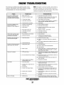
Engine Troubleshooting ......................................... 31
Troubleshooting Water Temperature and
Oil Pressure Gauges ............................................ 32
Lay-up and Recommissioning ............................... 33
WESTERBEKE 55A Torque Specifications ........ 35
Standard Hardware Torques ................................ 36
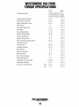
WESTERBEKE 55A FOUR Specifications ......... 37
WESTERBEKE 55A FOUR Parts Identification38
WESTERBEKE
WESTERBEKE CORPORATION' AVON INDUSTRIAL PARK
AVON, MA 02322' TEL: (508)'588-7700·' FAX: (508) 559-9323
1
INTRODUCTION
PRODUCT SOFTWARE
This WESTERBEKE Marine Diesel Engine is a product
of WESTERBEKE' S long years of experience and advanced technology. We take great pride in the superior
durability and dependable performance of our engines
and generators. Thank you for selecting WESTERBEKE.
Product software (tech data, parts lists, manuals,
brochures and catalogs) provided from sources other than
WESTERBEKE are not within WESTERBEKE'S
CONTROL.
In order to get the full use and benefit from your
engine, it is important that you operate and maintain it
correctly. This manual is designed to help you do this.
Please read this manual carefully and observe all the
safety precautions throughout. Should your engine require servicing, contact your nearest WESTERBEKE
dealer for assistance.
WESTERBEKE CANNOT BE RESPONSIBLE FOR
THE CONTENT OF SUCH SOFTWARE, MAKES NO
WARRANTIES OR REPRESENTATIONS WITH
RESPECT THERETO, INCLUDING ACCURACY,
TIMELINESS OR COMPLETENESS THEREOF AND
WILL IN NO EVENT BE LIABLE FOR ANY TYPE OF
DAMAGE OR INJURY INCURRED IN CONNECTION
WITH OR ARISING OUT OF THE FURNISHING OR
USE OF SUCH SOFTWARE.
This is your operators manual. A Parts Catalog is
also provided and a Technical Manual is available from
your WESTERBEKE dealer. Also, if you are planning
to install this equipment, contact your WESTERBEKE
dealer for WESTERBEKE'S installation manual.
WESTERBEKE customers should also keep in mind
the time span between printings of WESTERBEKE
product software and the unavoidable existence of earlier
WESTERBEKE manuals. In summation, product software provided with WESTERBEKE products, whether
from WESTERBEKE or other suppliers, must not and
cannot be relied upon exclusively as the definitive
authority on the respective product. It not only makes
good sense but is imperative that appropriate representatives of WESTERBEKE or the supplier in question be
consulted to determine the accuracy and currentness of
the product software being consulted by the customer.
WARRANTY PROCEDURES
Your WESTERBEKE Warranty is included in a
separate folder. If you have not received a customer
identification card registering your warranty 60 days after
submitting the warranty registration form, please contact
the factory in writing with model information, including
the unit's serial number and commission date.
TYPICAL CUSTOMER IDENTIFICATION CARD
NOTES, CAUTIONS AND WARNINGS
As this manual takes you through the operating procedures, maintenance schedules, and troubleshooting of
your marine engine, critical information will be highlighted by NOTES, CAUTIONS, and WARNINGS. An
explanation follows:
WESTERBEKE CORPORATION· AVON INDUSTRIAL PARK
AVON, MA 02322· TEL: (508) 558·7700· FAX: (508) 559-9323
Customer Identification
WESTERBEKE OWNER
MAIN STREET
HOMETOWN, USA
Model 55A Four
NOTE: An operating procedure essential to note.
A CAUTION: Procedures, which if not strictly
Ser. #U53890-48
observed, can result in the damage or destruction of
your engine.
Expires 7/20/97
A WARNING: Procedures, which if not properly
followed, can result in personal injury or loss of
life.
I"VVI WESTERBEKE
I Engines &
2
Generators
INTRODUCTION
(Continued)
SERIAL NUMBER LOCATION
ORDERING PARTS
An identification nameplate that displays the engine
model number and engine serial number is mounted on
the side of the engine manifold. Take the time to enter
this information on the blank decal provided below. This
will provide a quick reference when seeking technical information and/or ordering parts.
Whenever replacement parts are needed, always provide the engine model number and engine serial number
as they appear on the silver and black identification
nameplate located on the manifold. You must provide us
with this information so we can identify your engine. In
addition, include a complete part description and part
number for each part needed (see the separately furnished
Parts Catalog). Also insist upon WESTERBEKE packaged parts because will fit or generic parts are frequently
not made to the same specifications as original equipment.
NOTE: Component locations in this manual are referenced from the front of the engine which is the pulley/
drive belt end. Left and right sides are determined as
follows: imagine straddling the engine, facing in the
same direction as the front of the engine: the left side
is at your left, the right side is at your right.
UNDERSTANDING THE DIESEL ENGINE
The diesel engine closely resembles the gasoline
engine, since the mechanism is essentially the same.
The cylinders are arranged above a closed crankcase;
the crankshaft is of the same general type as that of a
gasoline engine, and the diesel engine has the same
types of valves, camshaft, pistons, connecting rods and
lubricating system.
PROTECTING YOUR INVESTMENT
Care at the factory during assembly and thorough testing
have resulted in a WESTERBEKE diesel engine capable
of many thousands of hours of dependable service. However the manufacturer cannot control how or where the
engine is installed in the vessel or the manner in which
the unit is operated and serviced in the field. This is up
to the buyer/owner-operator.
To a great extent, a diesel engine requires the same
preventive maintenance as a gasoline engine. Most
important are proper ventilation and proper maintenance
of the fuel, lubricating and cooling systems. Replacement
of fuel and lubricating filter elements at the time periods
specified and frequent checking for contamination
(water, sediment, etc.) in the fuel system are essential.
Also important is the consistant use of a brand of high
detergent diesel lubrication oil designed specifically for
diesel engines.
NOTE: Six important steps to ensure long engine life:
o
o
The diesel engine does differ from the gasoline engine,
however, in its method of handling and firing of fuel. The
carburetor and ignition systems are done away
with and in their place is a single component - the fuel
injection pump - which performs the function of both.
Proper engine installation and alignment.
An efficient well-designed exhaust system that includes an anti-siphon break to prevent water from
entering the engine.
o
Changing the engine oil and oil filters every 200 operating hours.
o
Proper maintenance of all engine components
according to the maintenance schedule in this
manual.
o
o
Use clean, filtered diesel fueL
Winterize your engine according to the "Lay-up and
Recommissioning" section in this manual.
I~I WSJERBEKE
I Engines & Generators
3
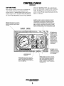
CONTROL PANELS
WESTERBEKE offers two optional panels- select
the instruction page that applies to the panel you purchased.
You will notice that when the engine is shut down with
the Key Switch turned OFF, the water temperature gauge
will continue to register the last temperature reading indicated by the gauge before electrical power was turned
OFF. The oil pressure gauge will also hold its reading.
The temperature gauge will once again register the engine's true temperature when electrical power is restored
to the gauge
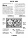
ADMIRALS PANEL
This manually-operated control panel is equipped with a
KEY SWITCH and RPM gauge with an ELAPSED
TIME meter which measures the engine's running time
in hours and in 1110 hours. The panel also includes a
WATER TEMPERATURE gauge which indicates water
temperature in degrees Fahrenheit, an OIL PRESSURE
gauge which measures the engine's oil pressure in
pounds per square inch, and a DC control circuit VOLTAGE gauge which measures the system's voltage. All
gauges are illuminated when the key switch is turned ON
and remain illuminated while the engine is in operation.
The panel also contains two rubber-booted push buttons,
one for PREHEAT and one for START.
A separate alarm buzzer with harness is supplied with
every Admiral Panel. The installer is responsible for
electrically connecting the buzzer to the four-pin connection on the engine's electrical harness. The installer
is also responsible for installing the buzzer in a location
where it will be dry and where it will be audible to the
operator should it sound while the engine is running.
The buzzer will sound when the ignition key is turned
ON and should silence when the engine has started and
the engine's oil pressure rises above 15 psi.
WATER TEMPERATURE GAUGE: THIS GAUGE IS
GRADUATED IN DEGREES FAHRENHEIT AND IS
ILLUMINATED WHILE THE KEY SWITCH IS
TURNED ON. THE ENGINE'S NORMAL OPERATING
TEMPERATURE IS 170°·190° F
OIL PRESSURE GAUGE: THIS GAUGE IS GRADUATED IN POUNDS PER SQUARE INCH (PSI) AND IS
ILLUMINATED WHILE THE KEY SWITCH IS
TURNED ON. THE ENGINE'S NORMAL OPERATING
OIL PRESSURE RANGES BETWEEN 30-60 PSI.
RPM GAUGE: REGISTERS REVOLUTIONS
PER MINUTE OF THE
ENGINE AND CAN BE
RECALIBRATED FOR
ACCURACY FROM
THE REAR OF THE
PANEL.
KEY SWITCH: PROVIDES
POWER ONLY TO THE
INSTRUMENT PANEL
CLUSTER. THE KEY
SWITCH SHUTS THE
ENGINE DOWN WHEN
THE KEY IS TURNED OFF.
HOUR METER: REGISTERS ELAPSED TIME,
AND SHOULD BE USED
AS A GUIDE FOR THE
MAINTENANCE
SCHEDULE.
/
PREHEAT BUTTON: WHEN PRESSED, ENERGIZES
THE ALTERNATOR'S EXCITER, THE FUEL LIFT
PUMP, THE FUEL SOLENOID ON THE INJECTION
PUMP, AND THE ENGINE'S GLOW PLUGS. IT BYPASSES THE ENGINE'S PROTECTIVE OIL PRESSURE ALARM SWITCH. IN ADDITION, THIS
BUTTON ENERGIZES THE START BUTTON.
DC VOLTMETER:
INDICATES THE AMOUNT
THE BATTERY IS BEING
CHARGED. SHOULD
SHOW 13V TO 14V.
AUTOMATIC ALARM SYSTEM
/
START BUTTON: WHEN PRESSED, ENERGIZES
THE STARTER'S SOLENOID WHICH CRANKS THE
ENGINE. THIS BUTTON WILL NOT OPERATE
ELECTRICALLY UNLESS THE PREHEAT BUTTON
IS PRESSED AND HELD AT THE SAME TIME.
HIGH WATER TEMPERATURE ALARM: AN ALARM BUZZER HAS
BEEN SUPPLIED WITH THE INSTRUMENT PANEL. IF THE ENGINE'S
FRESH WATER COOLANT REACHES 210° F (98°C), THIS SWITCH
WILL CLOSE SOUNDING THE ALARM WHICH WILL EMIT A CONTINUOUS SIGNAL.
LOW OIL PRESSURE ALARM: A LOW OIL PRESSURE ALARM
SWITCH IS LOCATED OFF THE ENGINE'S OIL GALLERY. THIS
SWITCH MONITORS THE ENGINE'S OIL PRESSURE. SHOULD THE
ENGINE'S OIL PRESSURE FALL TO 5 -10 PSI, THE SWITCH WILL
CLOSE SOUNDING THE ALARM. IN THIS EVENT, THE ALARM WILL
EMIT A PULSATING SIGNAL.
l-vvl WESJERBEKE
I Engines &
4
Generators
CONTROL
PANELS
(Continued)
CAPTAINS PANEL
COOLANT TEMPERATURE; and an alarm buzzer
for low OIL PRESSURE or high WATER TEMPERATURE. The RPM gauge is illuminated when the key
switch is turned ON and remains illuminated while the
engine is in operation.
This manually-operated control panel is equipped with
a KEY SWITCH; an RPM gauge; PREHEAT and
START buttons; an INSTRUMENT TEST button; three
indicator lamps, one for ALTERNATOR DISCHARGE,
one for low OIL PRESSURE, and one for high ENGINE
ALARM: THE ALARM WILL SOUND IF THE ENGINE'S OIL PRESSURE
FALLS BELOW 15 PSI. IN THIS EVENT, THE ALARM WILL EMIT A
PULSATING SIGNAL. THE ALARM WILL ALSO SOUND IF THE WATER
TEMPERATURE IN THE FRESHWATER COOLING CIRCUIT RISES TO
205°F. IN THIS EVENT, THE ALARM WILL EMIT A CONTINUOUS SIGNAL.
NOTE: THE ALARM WILL SOUND WHEN THE KEY SWITCH IS TURNED
ON. THIS SOUNDING IS NORMAL. ONCE THE ENGINE STARTS AND THE
ENGINE'S OIL PRESSURE REACHES 15 PSI, THE ALARM WILL SILENCE.
RPM GAUGE: REGISTERS REVOLUTIONS PER
'MINUTE OF THE ENGINE AND CAN BE RECALIBRATED FOR ACCURACY FROM THE REAR OF
THE PANEL.
/
TEST BUTTON: WHEN
PRESSED, TESTS THE
ALTERNATOR, THE OIL
PRESSURE, AND THE
WATER TEMPERATURE
CONTROL CIRCUITS.
WHEN PRESSED, THE
ALTERNATOR, THE OIL
PRESSURE, AND THE
WATER TEMPERATURE
INDICATOR LIGHTS ILLUMINATE IN ADDITION
TO SOUNDING THE
ALARM BUZZER.
KEY SWITCH: PROVIDES
POWER ONLY TO THE INSTRUMENT PANEL CLUSTER.
, THE KEY SWITCH SHUTS THE
ENGINE DOWN WHEN THE
KEY IS TURNED OFF,
PREHEAT BUTTON: WHEN PRESSED, ENERGIZES
THE ALTERNATOR'S REGULATOR, THE FUEL LIFT
PUMP, THE FUEL SOLENOID ON THE INJECTION
PUMP, AND THE ENGINE'S GLOW PLUGS. IT BYPASSES THE ENGINE'S OIL PRESSURE ALARM
SWITCH, IN ADDITION, THIS BUTTON ENERGIZES
THE START BUTTON.
START BUTTON: WHEN PRESSED, ENERGIZES
THE STARTER'S SOLENOID WHICH CRANKS THE
ENGINE. IT WILL NOT OPERATE ELECTRICALLY
UNLESS THE PREHEAT BUTTON IS PRESSED AND
HELD AT THE SAME TIME,
,....,., WESJERBEKE
I Engines &
5
Generators
DIESEL FUEL, ENGINE OIL
AND ENGINE COOLANT
DIESEL FUEL
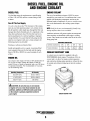
ENGINE COOLANT
Use fuel that meets the requirements or specification
of Class 2-D (ASTM), and has a cetane rating of #45
or better.
.
The use of an antifreeze mixture of 50/50 is recommended for year-round use. Use antifreeze that is compatible with aluminium components, and never mix
different brands of antifreeze. Do not use straight water,
this can be detrimental to the cooling system components.
Care Of The Fuel Supply
Use only clean diesel fuel! The clearance of the components in your fuel injection pump is very critical; invisible dirt particles which might pass through the filter can
damage these finely finished parts. It is important to buy
clean fuel, and keep it clean. The best fuel can be rendered unsatisfactory by careless handling or improper
storage facilities. To assure that the fuel going into the
tank for your engine's daily use is clean and pure, the
following practice is advisable:
NOTE: Lookfor the new environmentally-friendly long
lasting antifreeze that is now available.
Antifreeze mixtures will protect against an unexpected
freeze and they are beneficial to the engine's cooling
system. They retard rust and add to the life of the circulating pump seal.
ANTIFREEZE PROTECTION
Antifreeze concentration
Purchase a well-known brand of fuel.
Freezing Temperature
Install and regularly service a good, visual-type filterl
water separator between the fuel tank and the engine.
Raycor 500 FG or 900 FG is a good example of such
a filter.
Above 68°F (20°C)
SAE 30 or 10W-30
41°-68°F 5-20°C)
SAE 20 or 10W-30
Below 41°F (5°C)
SAE 10W-30
-4°F
(-20°C)
50%
60%
-40°F
(-40°C)
-58°F
(-50°C)
A coolant recovery tank kit is supplied with each
WESTERBEKE diesel engine. The purpose of this recovery tank is to allow for engine coolant expansion
and contraction during engine operation, without the loss
of coolant and without introducing air into the cooling
system.
Use a heavy duty engine oil with an API classification of
CF or CG4 or better. Change the engine oil after an
initial 50 hours of break-in operation, and every 200 hours
of operation thereafter. For recommended oil viscosity,
see the following chart:
Oil Viscosity
35%
COOLANT RECOVERY TANK
ENGINE OIL
Operating Temperature
23%
14°F
(-5°C)
A CAUTION: 00 not allow two or more brands
of engine oil to mix. Each brand contains its own
additives; additives of different brands could react
in the mixture to produce properties harmful to
your engine.
COOLANT RECOVERY TANK
6
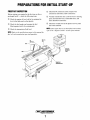
PREPARATIONS FOR INITIAL START-UP
PRESTART INSPECTION
o
Before starting your engine for the first time or after a
prolonged layoff - check the following items.
Check the DC electrical system. Inspect wire
connections and battery cable connections.
o
Visually examine the unit. Look for loose or missing
parts, disconnected wires, unattached hoses, and
check threaded connections.
o
Check the coolant level in the plastic recovery tank
and at the manifold.
o
Check the engine oil level; add oil to maintain the
level at the high mark on the dipstick.
o
Check the fuel supply and examine the fuel
filter/separator bowls for contaminants.
o
Check the transmission fluid level.
NOTE: If the engine has not yet been filled with coolant,
refer to the "Engine Coolant" section of this manual.
NOTE: Refer to the specifications pages in this manual for
fuel, oil, and transmission types and quantities.
OIL
DIPSTICK
FULL
COOLANT
RECOVERY
TANK
LDW----~1l!J
MANIFOLD
PRESSURE CAP
l-vvl WESJERBEKE
I Engines & Generators
7
STARTING/STOPPING PROCEDURE
STARTING PROCEDURE
A
CAUTION: Prolonged cranking intervals without
the engine starting can result in the engine exhaust
system filling with raw water. This may happen because the pump is pumping raw water through the
raw water cooling system during cranking. This raw
water can enter the engine's cylinders by way of the
exhaust manifold once the exhaust system fills. Prevent this from happening by closing the raw water
supply through-hull shut-off, draining the exhaust
muffler, and correcting the cause of the excessive
engine cranking. Engine damage resulting from raw
water entry is not a warrantable issue; the
owner/operator should keep this in mind.
Place the transmission in neutral and advance the throttle
control to slightly open.
A
CAUTION: Make certain the transmission is
in neutral. Starting in gear could result in serious
damage to your transmission, your boat, and
vessels nearby.
Tum the KEY SWITCH to the ON position (2
0' clock)
PREHEAT: Depress the PREHEAT switch. The voltmeter,
panel lights, gauges and meters, and fuel solenoid will be
activated. The PREHEAT switch should be depressed in
accordance with the following chart:
Once the engine starts, check instruments for proper oil
pressure and battery charging voltage.
NOTE: Never attempt to engage the starter while the
Temperature/Preheat
engine is running.
Atmospheric Temperature
Preheating Time
+41 °F( +5°C) or higher
Approx. 10 seconds
+41 °F( +5°C) to 23°F (-5°C)
Approx. 15 seconds
+23°F(-5°C) or lower
Approx. 20 seconds
Limit of continuous use
30 seconds before cranking
NOTE: Some unstable running may occur in a cold engine.
Depressing the Preheat switch for 10-15 second intervals
will help stabilize the engine RPM until the operating temperature reaches 170°-190°F (77°-88°C) and a propeller
load is applied to the engine. When the engine is running
and the preheat switch is depressed, a charging load on
the DC alternator will be discernible.
START: While still depressing the PREHEAT switch, depress the START switch. This will engage the start solenoid. Upon engine firing, release the START switch. Do
not release the PREHEAT switch until the oil pressure
reaches 15 psi. Then as long as the high water temperature and low oil pressure protective circuits do not activate, the engine will remain energized and continue
to run.
STARTING UNDER COLD CONDITIONS
Make certain the lubricating oil conforms with the ratings for
the prevailing temperature. Check the table on the engine
oil section of this manual.
The battery should be fully charged to minimize voltage
drop.
Use a sufficient amount of preheat to aid in starting.
See TemperaturelPreheat chart on this page.
NOTE: When starting:
A voltage drop will occur
when the preheat switch
is depressed.
STOPPING PROCEDURE
To stop the engine, bring the throttle to an idle position
and place the transmission in neutral. Allow the engine to
idle for a few moments to stabilize temperatures. Tum
the key to the OFF position. This opens the DC circuit to
the instrument panel and engine, de-energizing the fuel
solenoid on the injection pump, stopping fuel flow from
it and stopping the engine.
Should the engine not start when the START switch is
depressed for 10 to 20 seconds, release both switches and
wait 30 seconds; repeat the procedure above and preheat
longer. Never run the starter for more than
Made certain the key switch is in the OFF position
(12 o'clock). If the Key Switch is left ON, the battery
will discharge. An engine alarm buzzer is provided to
warn the operator of this condition (Key Switch ON).
The best method of preventing the battery from discharge
is to remove the key from the Key Switch after stopping
the engine.
30 seconds.
/"VVI WESJERBEKE
I Engines & GeneratDrs
8
BREAK-IN PROCEDURE
THE FIRST 50 HOURS
4. Avoid rapid acceleration, especially with a cold
engine.
Although your engine has experienced a minimum of one
hour of test operations to ensure accurate assembly and
proper operation of all systems, break-in time is required.
The service life of your engine is dependent upon how
the engine is operated and serviced during its initial 50
hours of use.
S. Use caution not to overload the engine. The presence
of a gray or black exhaust, and the inability of the
engine to reach its full rated speed, are signs of an
overload.
6. During the next 25 hours, the engine may be operated
at varying engine speeds, with short runs at full rated
rpm. A void prolonged idling during this break-in period.
Your new engine requires approximately 50 hours of initial conditioning operation to break in each moving part
in order to maximize the performance and service life of
the engine. Perform this conditioning carefully, keeping
in mind the following:
Breaking-in a new engine basically involves seating
the piston rings to the cylinder walls. This cannot be
accomplished by long periods of running at idle, nor by
early running at full rpm. Idle running may glaze the
cylinder walls, resulting in excessive oil consumption
and smoky operation. Excessive speed or heavy overloading, especially with a cold engine, may cause scoring
of the cylinder walls, producing similar results. Operate
the engine in moderation during the 50-hour break-in period. (Don't baby the engine, but do not abuse it.)
1. Start the engine according to the Starting Procedure
section in this manual; run the engine at fast idle
while checking that all systems (raw water pump, oil
pressure, battery charging) are functioning.
2. Allow the engine to warm up (preferably by running
at fast idle) until the water temperature gauge moves
into the 130° -140°F range.
3. While using the vessel, run the engine at varying engine speeds for the first 25 hours.
NOTE: See the Transmission section of this manual for
break-in information on your transmission.
rVtTl WESJERBEKE
I Engi_s & Generators
9
THE DAILY ROUTINE
CHECK LIST
START YOUR ENGINE
Each day before starting your engine, take a few
moments to run this check list:
NOTE: See Starting/Stopping Procedure in this manual for
more detailed instructions.
o
1. Put transmission in neutral, throttle advanced.
o
o
o
o
o
o
Visually inspect the engine for fuel, oil, or water
leaks.
2. Tum KEY to the ON position (2 o'clock)
Check the oil level (dipstick).
3. Depress PREHEAT (10 to 15 seconds).
Check the transmission fluid level.
4. While pressing PREHEAT, push START. As engine
fires - release START.
Check for loose wires at the alternator.
5. Hold PREHEAT until oil pressure reaches 15 psi
and/or alarm shuts off.
Check the starting batteries level (weekly)
Check drive belts for wear and proper tension
(weekly).
NOTE: Should engine fail to start, wait 30 seconds, repeat
Log your engine running time. These hours relate to
scheduled maintenance.
o
Check fuel supply; always keep fuel tank(s) as full as
possible.
o
o
Look for clean fuel in the fuel/water separator bowl.
the above procedure, and PREHEAT longer.
6. Allow a few minutes for the engine to warm at a
comfortable rpm (approx. 1200 rpm), then reduce the
rpm, shift into gear, and get underway.
Check the coolant level in the plastic recovery tank.
NOTE: Excessive loss of coolant indicates a cooling system leak. Check the entire system. If necessary, use a
cooling system pressure tester to pressurize the cooling
system to locate the area of leakage. In cases of excessive
coolant loss, refill the system as outlined in Preparations
for Initial Start-Up in this manual.
l-vvl WESTERBEKE
r Engines & Generators
10
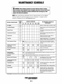
MAINTENANCE SCHEDULE
A WARNING: Never attempt to perform any service while the engine is running.
Wear the proper safety equipment such as goggles and gloves, and use the correct
tools for each job. Disconnect the battery terminals when servicing any of the
engine's DC electrical equipment.
NOTE: Many of the following maintenance jobs are simple but others are more difficult
and may require the expert knowledge of a service mechanic. A complete service
manual is availablefrom your WESTERBEKE dealer.
SCHEDULED MAINTENANCE
CHECK
EACH
DAY
HOURS OF OPERATION
50
100
250
500
750
1000 1250
EXPLANATION OF SCHEDULED
MAINTENANCE
0
0
Diesel No.2 octane rating of 45 cetane or better.
Engine Oil Level
0
Oil level should indicate between MAX. and LOW
on dipstick.
Transmission Fluid Level
0
Fluid level should indicate between MAX. and
LOW on dipstick
Coolant Level
0
Check at recovery tank; if empty, check at
manifold. Add coolant if needed.
Drive Belts
0
Inspect for proper tension ('h " to 'Is" depression)
and adjust if needed. Check belt edges for wear.
Visual Inspection of Engine
0
Fuel Supply
Fuel/Water Separator
Check for water and dirt in fuel (drain/replace if
necessary).
NOTE: Please keep engine surface clean. Dirt and
oil will inhibit the engine's ability to remain cool.
Throttle and Transmission
Control Cable
0
Adjust Engine Idle Speed
0
0
Fuel Filter
0
0
0
Check for fuel, oil and water leaks. Inspect
wiring and electrical connections. Keep bolts &
nuts tight.
Check for loose fittings, cotter pins, etc.
Lubricate with WD-40 or equivalent.
Adjust to (750-1000 rpm).
0
0
Initial change at 50 hrs, then change every
250 hrs.
Starting Batteries
(and House Batteries)
0
Every 50 operating hours check electrolyte levels and make sure connections are very tight.
Clean off excessive corrosion.
Engine Oil
0
0
Initial engine oil & filter change at 50 hrs., then change both every 100 hours.
• Adjust the Valve Clearances
0
Lubricate Panel Key Switch
with" Lockeze"
TransmiSSion Fluid
0
0
0
0
0
0
0
0
0
0
At 1st 100 hrs. then each year at winterizing.
0
0
Initial fluid change at 50 hrs., then every 250
hrs. or at winterizing.
Replace element filter. Clean or replace elements.
0
0
0
·WESTERBEKE recommends this service be performed by an authorized mechanic.
/"VVI WESJERBEKE
I Engines &
11
Initial adjustment at 50 hrs., then every 50Q hrs.
(Do not retorque the cylinder head)
0
0
Air Cleaner
Exhaust System
0
GeneratDrs
Initial check at 50 hrs., then every 250 hrs.
Inspect for leaks. Tight connections check,
siphon brake operation. Check the exhaust
elbow for carbon and/or corrosion buildup on
inside passages; clean and replace as
necessary.
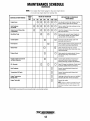
MAINTENANCE
SCHEDULE
(Continued)
NOTE: Use engine hour meter gauge to log your engine hours
or record your engine hours by running time.
SCHEDULED MAINTENANCE
CHECK
EACH
DAY
HOURS OF OPERATION
50
100
250
500
750
1000 1250
EXPLANATION OF SCHEDULED
MAINTENANCE
D D D D D D
Hose should be hard & tight. Replace if soft or
spongy. Check & tighten all hose clamps.
Heat Exchanger
Zinc Anode
D D D D D D D
Clean or replace. Open heat exchanger end cap
and clean out debris.
Electric Fuel Lift Pump Filter
(if applicable)
D
D D D D D
Initial filter change at 50 hours, then change
filter every 250 hours.
D
D
Remove pump cover and inspect impeller for
wear; replace if needed. Also replace gasket.
Lubricate both when reassembling.
D
Drain, flush, and refill cooling system with
appropriate anti-freeze mix.
Engine Hoses
Raw Water Pump
D
D
Coolant System
D
*Fuellnjectors
Check and adjust injection opening pressure and
spray condition (see Engine Adjustments).
*Starter Motor
D
D
Check solenoid and motor for corrosion.
Remove and lubricate. Start. motor pinion drive.
Clean and lubricate.
*Preheat Circuit
D
D
Check operation of preheat solenoid. Remove
and clean glow plugs; check resistance
(4-6 ohms).
*Engine Cylinder Compression
and Valve Clearance
D
D
Incorrect valve clearance will result in poor
engine performance; check compression
pressure and timing, and adjust valve clearances.
D
Check DC charge from alternator. Check mounting bracket; tighten electrical connections.
DC Alternator
D
D
Heat Exchanger
D
Remove; have professionally cleaned and
press ure tested.
Transmission Oil Cooler
D
Remove; have professionally cleaned and
pressure tested.
Engine Transmission
Damper Plate
D
Chattering at idle and low rpms is an indication
of damper plate wear. Remove and replace.
Engine Timing Belt
D
Remove and replace.
NOTE: Failure to replace the timing belt at the
recommended interval could result in timing
belt failure resulting in major damage to the
engine.
'WESTERBEKE recommends this service be performed by an authorized mechanic.
I~l WSJERBEKE
I Engines & Gene",tors
12
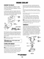
ENGINE COOLANT
CHANGING THE COOLANT
Start the engine and bring it to operating temperature.
Monitor the coolant in the manifold and add as needed.
Fill the manifold to the filler neck and install the pressure
cap.
The engine's coolant must be changed every eight to
twelve months depending on the engine's use. If the
coolant is allowed to become contaminated, it can lead
to overheating problems.
Remove the cap on the coolant recovery tank, fill with
coolant to halfway between LOW and MAX, and replace
the cap.
A coolant recovery tank allows for engine coolant expansion and contraction during engine operation, without any significant loss of coolant and without introducing air into the
cooling system. This tank should be located at or above the
engine manifold level, and be easily accessible.
.\:>?i~:":';';~---
Run the engine and observe the coolant expansion flow
into the recovery tank.
After checking for leaks, stop the engine and allow
it to cool. Coolant should draw back into the cooling
system as the engine cools down. Add coolant to the
recovery tank if needed. Clean up any spilled coolant.
COOLANT
RECOVERY
TANK CAP
NOTE: Periodically check the condition of the pressure cap.
Ensure that the upper and lower rubber seals are in good
condition and check that the vacuum valve opens and
closes tightly. Carry a spare cap.
~--- COOLANT
RECOVERY
TANK
THERMOSTAT
A thermostat, located near the manifold at the front of the
engine, controls the coolant temperature as it continuously flows through the closed cooling circuit. When
the engine is first started the closed thermostat prevents
coolant from flowing (some coolant is by-passed through
a hole in the thermostat to prevent the exhaust manifold
from overheating). As the engine warms up the thermostat gradually opens. The thermostat is accessible and can
be checked, cleaned, or replaced easily. Carry a spare
thermostat and gasket.
COOLANT EXPANSION
Drain the engine coolant by loosening the drain plug on
the engine block and opening the manifold pressure cap.
Flush the system with fresh water, then start the refill
process. See the Parts Identification photos in this manual for locations.
WATER
TEMPERATURE
ALARM
NOTE: The petcock on the heat exchanger can also be
used to drain engine coolant.
A WARNING: Beware of the hot engine coolant.
WATER
TEMPERATURE
SENDER
Wear protective gloves.
TO REFILL WITH COOLANT
With the enginge running in idle, slowly pour clean
premixed coolant into the manifold.
NOTE: Open the air bleed petcock on the heat exchanger
to help remove air from the system. When a steady flow
of coolant appears at the drain plug opening, close the
water drain plug and continue to fill the system until the
manifold remains full. Close the petcock on the heat
exchanger when antifreeze flows from it.
THERMOSTAT
I~l WSJ&lBEKE
I Engines & GeneratDrs
13
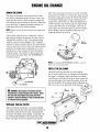
ENGINE OIL CHANGE
DRAIN THE SUMP
filter when unscrewing it to catch any oil left in the filter.
Inspect the old oil filter as it is removed to make sure that
the rubber sealing gasket comes off with the old oil filter.
If this rubber sealing gasket remains sealed against the
engine block, gently remove it. When installing the new
oil filter element, wipe the filter gasket's sealing surface
on the engine block free of oil and apply a thin coat of
clean engine oil to the rubber gasket on the new oil filter.
Screw the filter onto the threaded oil filter stub, and
tighten the filter firmly by hand.
The engine oil should be warm. Remove the oil drain
hose from its attachment bracket and lower it into a container and allow the oil to drain, or attach a pump to the
end of the drain hose and pump out the old oil. Make sure
the oil drain hose is capped and properly secured in its
holder after all the old oil has been drained.
NOTE: Thread size for the lube oil drain hose capped end
is 1/4 NPT.
Always observe the old oil as it is removed. A yellow/
gray emulsion indicates the presence of water in the oil.
Although this condition is rare, it does require prompt
attention to prevent serious damage. Call a competent
mechanic if water is present in the oil. Raw water present
in the oil can be the result of a fault in the exhaust system
attached to the engine and/or a siphoning of raw water
through the raw water cooling circuit into the exhaust,
filling the engine. This problem is often caused by the
poor location of the syphon brake. See WESTERBEKE'S
Installation Manual.
SPIN-ON
OIL FILTER
q _ _-OIL
COOLER
NOTE: Use genuine WESTERBEKE oil filters - generic
filters are not recommended.
REFILL THE OIL SUMP
~
Add fresh oil through the filler cap. After refilling
the oil, run the engine for a few moments while checking
the engine's oil pressure. Make sure there is no leakage
around the new oil filter or from the oil drain system, and
then stop the engine. Then check the quantity of oil with
the lube oil dipstick. If the engine requires additional oil,
fill to, but not over, the high mark on the dipstick.
OIL DRAIN HOSE
~ OIL CONTAINER
A WARNING: Used engine oil contains harmful
contaminants. Avoid prolonged skin contact. Clean
skin and nails thoroughly using soap and water.
Launder or discard clothing or rags containing used
oil. Discard used oil properly.
FULL-+--ra
LOW-_ _~1frI
REPLACE THE OIL FILTER
When removing the used oil filter, you may find it helpful
and cleaner to punch a hole in the upper and lower portion of
the old filter to drain the oil from it into a container before
removing it. This helps to lessen spillage. An automotive filter wrench should be helpful in removing the old oil filter.
Place some paper towels and a plastic bag around the
!-VVI WESTERBEKE
rEngines & Generators
15
FUEL SYSTEM
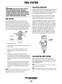
A WARNING: Shut off the fuel valve at the tank
when servicing the fuel system. Take care in
catching any fuel that may spill. DO NOT allow any
smoking, open flames or other sources of fire near
the fuel system when servicing. Ensure proper ventilation exists when servicing the fuel system.
FUEL WATER SEPARATOR
A primary fuel filter of the water separating type must be
installed between the fuel tank and the engine to remove
water and other contaminants from the fuel before they
can be carried to the fuel system on the engine.
Most installers include a type of filter/water separator
with the installation package as they are aware of the
problems that contaminants in the fuel can cause.
FUEL FILTERS
A typical fuel filter/water separator is illustrated in this
diagram. This is the Raycor Model 500 MA. Keep in
mind that if a water separator type filter is not installed
between the fuel supply tank and engine-mounted fuel
system, any water in the fuel will affect the fuel pump,
engine filter, and injection equipment. The ownerl
operator is responsible for making certain the fuel
reaching the engine's injection equipment is free of
impurities. This process is accomplished by installing
and maintaining a proper filtration/separation system.
The fuel injection pump and the fuel injectors are
precisely manufactured and they must receive clean
diesel fuel, free from water and dirt. To ensure this flow
of clean fuel, the fuel must pass through at least two fuel
filters, a fuel/water separator and the engines spin-on fuel
filter. Visually inspect, clean, and change these filters
according to the maintenance schedule in this manual.
O-RING----
SPIN-ON
FUEL FILTER-_---JI~~~
L
FILTER/WATER
/SEPARATOR
1. Shut fuel supply off.
2. Loosen the fuel filter, turning counterclockwise with
a filter wrench.
3. Using a rag, wipe clean the sealing face on the
housing bracket so the new filter can be seated
properly.
4. Lightly oil the sealing O-ring on the new filter.
To reinstall, turn the filter assembly counterclockwise
carefully until the O-ring contacts the sealing surface
of the housing bracket. Turn 2/3 further with the filter
wrench.
FUEL INJECTION PUMP CONTROL
The fuel injection pump is precisely adjusted; most
of the adjustments are sealed, so be careful not to break
them. When an adjustment is necessary, contact your
WESTERBEKE dealer.
5. Turn on the fuel and manually prime the fuel filter
using the priming pump on top ofthe housing. Use
a slow steady pumping action until resistance is felt.
The filter is now primed and the engine is ready
to start.
NOTE: There is no warranty on engines with broken high
rpm governor adjustment seals.
NOTE: The idle adjustment screw can be readjusted to pro-
NOTE: The cartridge contains fuel. Take care not to spill
vide for a satisfactory idle speed with each specific installation.
it during disassembly. Peiform the "fuel system air
bleeding" after replacing the spin-on filter.
f"VtTf WESJERBEKE
(Engines & Generators
16
FUEL(Continued)
SYSTEM
FUEL ADDITIVES
If fungus or bacteria is causing fuel problems, you should
have an authorized dealer correct these problems. Then
use a diesel fuel biocide to sterilize the fuel (follow the
manufacturer's instructions).
SPARES
While the likelihood of having to service the fuel system
at sea is slim, the possibility does exist. Therefore, we
recommend that banjo washers, injector seat washers,
and a fuel filter be carried on board at all times. (See the
Spares And Accessories brochure"). Purchase needed
spares from your local WESTERBEKE dealer or
distributor. If a leak should develop at a banjo washer
that cannot be corrected by a simple tightening of the
fitting, replace the sealing washer with a replacement
found in the engine fuel hardware kit for your model.
A CAUTION: When using the preheat function,
keep in mind that the preheat elements (glow plugs)
are also energized; take care not to overheat them!
Once the fuel filter assembly is free of air and the bleed
screw tightened, use the preheat button or slowly pump
the primer pump for 10 to 20 seconds to force any air
between the filter housing and injection pump out of the
system to the tank via the return line.
In cases where excessive amounts of air exist in the
fuel system, follow the above procedure but in addition,
loosen all the high pressure injector lines (not injectors)
and crank the engine starter motor; as fuel spurts from
between the nut and the line, tighten the injector lines in
sequence and then tighten the bleed screw.
NOTE: Do not attempt this procedure on a hot engine.
PRIMING (BLEEDING) THE FUEL SYSTEM
The on-engine fuel system is virtually self priming.
Under ordinary circumstances the engine's electric fuel
lift pump, which is energized by the key switch/preheat
button, will supply a continuous flow of fuel from the
tank. This fuel is drawn through the fuel/water separator
to the engine lift pump, the primary spin-on fuel filter,
and the injection pump.
A WARNING: Always wear protective clothing,
safety glasses and gloves when bleeding high pressure injector lines.
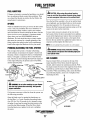
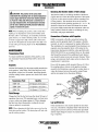
AIR CLEANER
Dual air cleaner filters are located on the top of the
engine manifold. These filters should be inspected,
cleaned, and/or replaced at maintenance periods. With
the engine turned off, remove the single hex bolt, lift the
manifold top, and the dual air cleaner filters become
accessible. When reassembling, make certain the filters
are positioned properly, and do not overtighten when
refastening the bolt.
FUEL LIFT PUMP
A
WARNING: 00 not allow smoking or open flames
near the fuel system when servicing. Also provide
proper ventilation.
If it becomes necessary to bleed air from the system, use
the following procedure:
Open the bleed screw by turning the thumbscrew on
the fuel filter 1 or 2 turns. Energize the preheat button
(key ON) for 10 to 20 seconds or do it manually using
the palm of your hand to pump the primer pump on the
top of the fuel filter housing. When fuel flows freely
from the bleed screw, tighten, but do not overtighten,
the screw.
AIR CLEANER
17
DC ELECTRICAL SYSTEM
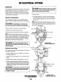
DESCRIPTION
A. WARNING: Before starting the engine make certain
The charging system consists of an alternator with a mounted
voltage regulator, an engine DC wiring harness, a mounted
DC circuit breaker, and a battery and connection wires.
Because of the use of integrated circuits (IC's) the electronic
voltage regulator is very compact and is mounted internally
or on the back of the alternator.
that everyone is clear of moving parts! Keep away from
sheaves and belts during test procedures.
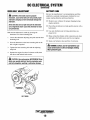
5. Start the engine.
6. The voltage reading for a properly operating alternator
should be between 13.5 and 14.5 volts. If your alternator
is over- or undercharging, have it repaired at a reliable
service shop.
Alternator Troubleshooting
If you suspect that the alternator is not producing enough
voltage to charge the engine's battery, check the following:
NOTE: Before removing the alternator for repair, use your
voltmeter to ensure that i 2 volts DC excitation is present at
the R terminal if the previous test showed only battery voltage at the B output terminal.
A WARNING: Afailed alternator can become very
hot. 00 not touch until the alternator has cooled down.
o Make certain your alternator is securely mounted.
o Check the drive belts for proper tension.
.14 GRAY=====O=~_-r-_
o Inspect for loose or disconnected wires at the alternator.
NOTE: An isolator with a diode, a solenoid, or a battery
selector switch is usually mounted in the circuit to isolate the
batteries so the starting battery is not discharged along with
the house batteries. If the isolator is charging the starting
battery but not the house battery, the alternator is OK and
the problem is in the battery charging circuit.
~~e;~~~~~F~ ~~i#====#14BRDWN
'14 PINKJBlUE -tHH4I?~
A WARNING: Shut off the engine battery switch or
TYPICAL 51 AMP
ALTERNATOR CONNECTIONS
disconnect from the battery when working on the engine
electrical system.
'14 BRD\"'N=====i~@
Checking for Proper Voltage
If you suspect the alternator has failed perform the following
tests with the engine off:
~~~~=f10RED
.14 RED==f==~~iS-+......
1. Using a voltmeter, connect the voltmeter red wire clip to
the output terminal B+.
2. Connect the voltmeter negative wire to any ground on the
engine.
. 3. Check the battery voltage. It should read 12 to 12 volts.
4. Check the voltage between the alternator (+) positive terminal B and any engine ground. If the circuit is good, the
voltage at the alternator should be the same as the battery
(unless there's an isolator in the circuit, then the reading
would be zero).
.l;;.2\,I:;' ~~::=C:CC3l!§
.14 PINKJBlUE
rr!?J~~=:::. .14 BROWN
A CAUTION: To avoid damage to the battery charging
circuit, never shut off the engine battery switch when
the engine is running!
rvvl WESIERBEKE
I Engines & Generators
18
OPTIONAL 72 AMP
,
ALTERNATOR CONNECTIONS
DC ELECTRICAL
SYSTEM
(Continued)
DRIVE BELT ADJUSTMENT
BATTERY CARE
Review the manufacturer's recommendations and then
establish a systematic maintenance schedule for your
engine starting batteries and house batteries.
A CAUTION: Drive belts must be properly
tensioned. Loose drive belts will not provide proper
alternator charging and will eventually damage the
alternator.
Drive belts that are too tight will pull the alternator
out of alignment and/or cause the alternator to wear
out prematurely.
Belt tension adjustment is made by pivoting the
alternator on its base mounting bolt.
1. Loosen the alternator adjusting strap bolt and the base
mounting bolt.
2. Pivot the alternator on the base mounting bolt to the
left or right as required.
o
Monitor your voltmeter for proper charging during
engine operation.
o
Check the electrolyte level and specific gravity with a
hydrometer.
o
Use only distilled water to bring electrolytes to a
proper level.
o
Make certain that battery cable connections are clean
and tight to the battery posts (and to your engine).
o
Keep your batteries clean and free of corrosion.
A
WARNING: Sulfuric acid in lead batteries can
cause severe burns on skin and damage clothing.
Wear protective gear.
3. Tighten the base mounting bolt and the adjusting
strap bolt.
4. Operate the engine for about 5 minutes at idle, then
shut down and recheck belt tension.
A
CAUTION: Use only genuine WESTERBEKE Drive
Belts; poor quality belts will lead to premature wear
and belt elongation resulting in alternator damage.
BELT TENSION
I~I WESJERBEKE
I Engines & Generators
19
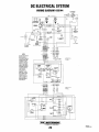
DC ELECTRICAL SYSTEM
WIRING DIAGRAM #39144
"
"
110
R.
R
IU PHI(
r~11
I
Il!ll.
I(~E
MOOnS.
i6i
SEE NOTE
11
'~
-9'
I
I
+~
~~
BAnERY
®
$I
NOTE:
AN ON-OFF SWITCH
SHOULD BE INSTALLED BETWEEN
THE BATIERY AND
STARTER TO DISCONNECT THE BATTERY IN AN EMERGENCY AND WHEN
LEAVING THE BOAT
A SWITCH WITH A
CONTINUOUS
RATING OF 175
AMPS AT 12 VDC
WILL SERVE THIS
FUNCTION. THIS
SWITCH SHOULD
NOT BE USED TO
MAKE OR BREAK
THE CIRCUIT.
ADMIRAL
PANEL
-,
"
CAPTAIN
PANEL
oz
;;
~~~~~--,
o
ALT.
UIP
III ORN
.......
OP.
RN
I,a BlK
118BlK
L
_
_
_
_
_
_
_
_
_
L~:::::::j'tt"~"~'::::::::::::::::::::::::::::::::~____l
111I8l11
____
I
I
I
I
I
I
I
I
I
I
I
I
I
I
I
..JI
!"'MTI WESJERBEKE
I
Engines & Generators
20
Revised
October 2000
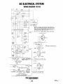
DC ELECTRICAL SYSTEM
WIRING DIAGRAM #39144
r---~~--------------------_+
-----1
I
I
I
I
I
I
I
I
I
AL TERIfATOR
rT;,;-;.~-----1
LIFT PUMP
I
~-+~-r------r.-~P
-R- TERM.
I
I
I
fUn
U .jDac~l:
~
.--+-+-+____---<'-'5run
0.=.: &II~I_
.WM(I
SOL.
I
O.P.
I
SENDER
=1
I
12080 &. 308ITI ONLY
L __
~~~~
__ I
NOTES:
I.
THIS PRODUCT IS PROTECTED BT A MANUAL RESET CIRCUIT BR[AKER LOCATEO NEAR THE
STARTER.
EXCESSIVE CURRENT WILL CAUSE THE BREAKER TO TRIP AND THE [NGINE WILL
SHUT DOWIf.
THE aUILOER/OWNER MUST BE SURE THAT THE INSTRUMENT PANEL • • IRING, AND
[NGIIf[ ARE INSTAllED TO PREVENT CONTACT BETW[EN [LEeTAICAL DEVICES AND SEAWATER.
l. AN ON-Off SWITCH SHOULD BE INSTALLED BETW[(N THE !!IArTUY AND STARTER TO
DISCONNECT THE BATTERY IN AN [M[RGENCY AND WH[N LEAVING THE SOAT.
A SWITCH
WITH A CONTINUOUS RATING
115 AMPS.
AT 11 YDC WILL SERVE THIS FUNCTION.
THIS
SWITCH SHOULD NOT SE USED TO MAlE OR BREAK THE CIRCUIT.
or
3. THE PINK WIRE AT PLUG 2 IS UMUS[D AND SHOULD 8E Irc$ULAT(D. CAPTAIN PArcEL ONLY •
'AT
ADMIRAL
PANEL
rACHON£TER
NET
S
sw.
GND
••
THE GRAT WIRE AT PLUG 2 IS UNUSED AND SHOULD 8E
MITSUBISHI
50 AMp
INSULATED. ADMIRAL PANEL ONLY.
ALT.
OG.
110
RN
114 P R
II 4 GRA
PRESTOllTE\LEECE-NEVILLE 90 AMP. ALT.
NOTE;
WIRE rOR BATTERT ATTATCHMENT WILL NEED
TO BE UPGRADED TO AN 8 GAUGE FROM 10 GAUGE
IICTA"
IU BRN
CAPTAIN
PANEL
LAMP
TEST
sw.
n
51
1104 PINK
03
AMP
~PRESTQLITE
ALTERNATOR
B2B
STANDARD ALTERNATOR ON THE
mBlJ:i.6:C,~c
~B
IlI:.
72 AMP
At T
IlI:.\-_________________
It 14 BRN
0UNIVERSAI PROPUlSION
PRESTOI I TE 51 AMP
AL T
OPTIONAL AI TERNATORS®
USA, ISOA. ItoA, LESlU ALTERNATORS
AYAIlAIIl( Q" THE !tsaR UItIY nr;:IY lOCIY eZltIY
IOgYI
'lom;;YI ONP
®
/-vvl WESTERBEKE
I Engines &
21
Generators
Revised
October 2000
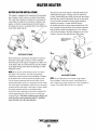
WATER HEATER
WATER HEATER INSTALLATIONS
This engine is equipped with connections for the plumbing of engine coolant to heat an on-board water heater.
The water heater should be mounted in a convenient location either in a high or low position in relation to the
engine, so that the connecting hoses from the heater to
the engine can run in a reasonably direct line without any
loops which might trap air.
The pressure cap on the engine's manifold should be installed after the engine's cooling system is filled with
coolant. Finish filling the cooling system from the remote
tank after the system is filled and is free of air and exhibits good coolant circulation. During engine operation,
checking the engine's coolant should be done at
the remote tank and not at the engine manifold cap. The
hose connection from the heater to the remote expansion
tank should be routed and supported so it rises continuously from the heater to the tank, enabling any air in the
system to rise up to the tank and out of the system.
(~-...J'.~~
REMOTE EXPANSION
TANK 1124117
I
I
I
I
,
I
...J,
I
I
.....
OIL
COOLER
I
"....J
HEATER BELOW THE ENGINE
Hoses should rise continuously from their low point at
the heater to the engine so that air will rise naturally
from the heater to the engine. If trapped air is able to rise
to the heater, then an air bleed petcock must be installed
at the higher fitting on the heater for bleeding air while
filling the system.
I
I '
i, I!
)
NOTE: If any portion of the heating circuit rises above
,
"
I
J
_./.
.
'
HEATER ABOVE THE ENGINE
the engine's own pressure cap, then a pressurized
(aluminum) remote expansion tank (Kit #024177) must
be installed in the circuit to become the highest point.
Tee the remote expansion tank into the heater circuit,
choosing the higher of the two connections for the return.
Tee at the heater, and plumb a single line up to the tank's
location and the other back to the engine's return. Install
the remote expansion tank in a convenient location
so the fresh water coolant level can easily be checked. The
remote expansion tank will now serve as a check and
system fill point. The plastic coolant recovery tank is not
used when the remote expansion tank kit is installed,
since this tank serves the same function.
NOTE: An air bleed petcock is located on the engine's
heat exchanger. Open this petcock when filling the engine's fresh water system to allow air in the exchanger to
escape. Close tightly after all the air is removed.
I~I WESIERBEKE
I Engines & Generators
22
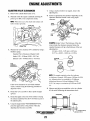
-ENGINE ADJUSTMENTS
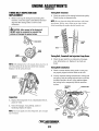
ADJUSTING VALVE CLEARANCES
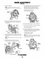
7. Using a small screwdriver or magnet, remove the
adjusting disc.
1. Remove the cylinder head rocker cover.
8. Select an appropriate disc thickness depending on the
2. Manually rotate the engine crankshaft and bring #1
piston up on TDC of its compression stroke.
clearance measured. Install it and verify proper
clearance.
NOTE: When this occurs, the intake and exhaust cam
lobes will face upwards.
EXAMPLE (Intake Valve): The thickness of the disc
removed plus the clearance measured minus the
standard clearance will give the thickness of the new
adjusting disc.
4.0 mm + (0.30 - 0.25 mm) =4.05 mm
0.157 in + (0.012 - 0.010 in) = 0.159 in
3. Measure the valve clearance of #1 cylinder by using a
thickness gauge.
Standard Valve Clearances (Engine Cold):
Intake: 0.20 - 0.30mm (0.008 - 0.012 in)
Exhaust: 0.30 - 0.40mm (0.012 - 0.016 in)
VALVE
CLEARANCE
MEASUREMENT.
NOTE: The number marked on the disc indicates
its thickness. Example: 3825 means 3.825mm (0.1056
in). Adjusting discs are available in 25 different
thicknesses between 3.40 and 4.60mm (0.13390.1811 in) range, at variations of 0.050 mm (0.002
in).
If the valves clearances are not within standard
values, continue using the following procedure to
adjust the valves.
9. Measure and adjust as needed the valves in cylinders
#3, #4 and #2 following the instructions above.
4. Rotate the valve cam lobe so that it points straight
upward.
CAM (INTAKE)'\...
5. Rotate the tappet so that one of the notches is facing
the exhaust manifold. This allows for better access to
the adjusting disc.
VALVE
CLEARANCE
6. Using the tappet holder WESTERBEKE #41978,
press the tappet down to the position where the
adjusting disc becomes accessible.
23
ENGINE ADJUSTMENTS
(Continued)
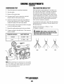
Timing Belt Tensioner
TIMING BELT INSPECTION AND
REPLACEMENT'
1. Check the rotation of the timing belt tensioner pulley.
Check for play or abnormal noise.
1. Before removing the timing belt and timing belt
tensioner, rotate the engine crankshaft by hand and
align the three timing marks as shown in the
illustration.
NOTE: Do not clean the timing belt tensioner with cleaning solvents. If dirty, use a clean rag to wipe it clean.
Avoid scratching the suiface the belt travels over.
A
CAUTION: After removal of the timing belt,
DO NOT rotate the crankshaft or camshaft; the
pistons will damage the opened valves.
OAMAGE,/
WEAR
~nM"G.AA~
OAMAGE,
WEAR
I
",
. I:" .
. ' ','....
,~
. :., :.
TIMING
MARKS
Timing Belt, Camshaft And Injection Pump Gears
1. Check the gear teeth for any indication of damage,
wear, deformation, etc. Replace if any faults are
found.
NOTE: If the timing belt is to be reused, draw an arrow on
the belt pointing in the direction of the belts rotation.
Replace it in the same direction.
Timing Belt Installation
1. Check to ensure that the timing marks on the gears
are properly aligned with the marks on the case.
2. Loosely install the timing belt tensioner, locking bolt
and spring. Push the timing belt tensioner toward the
lock bolt to the left as far as it will go and then tighten
the locking bolt to temporarily hold the tensioner
in place.
DIRECTION
ARROW
Inspection
1. Replace the timing belt if it is contaminated with oil,
grease or water.
2. Check for damage, wear, peeling, cracks or
hardening. Replace if suspect.
LOCKING
BOLT
NOTE: Never forcefully twist the timing belt; turn it inside
out or bend it.
TIMING BELT
TENSIONER
I~l WESTERBEKE
I Engines & Generators
24
ENGINE ADJUSTMENTS
(Continued)
3. Install the timing belt.
NOTE: If reinstalling the original belt, be sure to
install with the arrow in the correct direction of belt
rotation.
7. Re-check the timing mark positions between the three
gears and the gear case. Check the timing belt
deflection at the point on the belt shown in the
illustration with a pushing force of 10 kg (22Ib).
Standard Deflection (unit cold):
10.8-12.9 mm (0.43-0.51 in)
DIRECTION
ARROW
4. Release the timing belt tensioner lock bolt to allow
the tensioning spring tensionor to bring pressure on
the timing belt.
8. Install the timing belt left cover with its rubber seal.
9. Install the timing belt right cover with its rubber seal.
Bolt torque for timing belt cover bolts:
0.7-1.0 m-kg (5-7 ft-Ib)
10. Install the crankshaft pulley and torsional damper
onto the timing belt drive gear with the semicircular
(woodruff) key. Tighten the attachment.
Crankshaft pulley bolt torque:
2.3-3.3 m-kg (17-24 ft-Ib)
5. Turn the crankshaft twice in the direction of normal
engine rotation (clockwise) to equalize tension on the
timing belt.
NOTE: When installing the torsional damper onto the
timing belt drive gear, align the mark on the damper
with the knock pin on the gear.
NOTE: Do not turn the engine in reverse of its normal
rotation.
TIMING BELT
COVER (RIGHT)
6. Tighten the timing belt tensioner lock bolt.
Lock bolt torque: 3.2-4.7 m-kg (23-34 ft-Ib)
TIMING BELT
COVER (LEFT)
I"VVJ WESJERBEKE
r Engines & Generators
25
ENGINE ADJUSTMENTS
(Continued)
COMPRESSION TEST
FUEL INJECTION NOZZLE TEST
1. Warm the engine up to operating temperature.
When the injection starting pressure is too high or too
low or the fuel spray pattern is improper, an abnormal
fuel combustion takes place in the engine leading to
lowered power output, blackish exhaust smoke and unwanted combustion noise. Further, it can cause a piston
seizure or piston damage if not corrected. In such cases,
the injection nozzle test should be performed and the
faulty nozzle(s) replaced as required.
2. Stop the engine.
3. Remove all four glow plugs.
4. Disconnect the DC power connection to the fuel
shutoff solenoid on the injection pump.
5. Install the compression tester glow plug adapter in
the glo\y plug opening of #1 cylinder. Connect the
compression gauge to the glow plug adapter.
Use an injection nozzle tester to check the static injection
starting pressure and condition of the spray pattern every
800 operating hours.
6. Crank the engine with the starter and allow the gauge
to reach its maximum reading.
Injection nozzle pressure is 1920 psi + 71 psi
(135 kg/cm2 + 5 kg/cm2.
7. Record the reading and proceed to the next cylinder.
8. Compare readings to the table below. Take corrective
action as needed.
Compression pressure
A
WARNING: When testing a nozzle beware that
high pressure might blow off the light oil and cause
injury. Keep away from the nozzle end!
kg/cm 2(lb/in2)-rpm
Standard
30 (426) - 200
Limit
27 (384) - 200
GOOO
NOTE: Whenpeiforming the compression test, shut off the
raw water supply to the engine mounted raw water pump.
This is to prevent filling of the exhaust system with raw
water while peiforming the test.
l-vvl WESTERBEKE
I Engines &
26
Generators
POOR
HBW TRANSMISSION
INITIAL OPERATION
LOCKING THE PROP
All HBW marine transmissions are test-run on a test
stand with the engine at the factory prior to delivery.
For safety reasons the fluid is drained before shipment.
Locking of the propeller shaft by an additional brake is
not required: use the gear lever position opposite your direction of travel for this purpose. Never put the gear lever
in the position corresponding to the direction of travel of
the boat.
Fill the gearbox with Automatic Transmission Fluid
(DEXRON II or DEXTRON Ill). The fluid level should be
up to the index mark on the dipstick. To check the fluid
level, just insert the dipstick, do not screw it in. Screw
the dipstick into the case after the fluid level is checked,
and tighten. Do not forget the sealing ring under the hexhead of the dipstick. Check for leaks and change the fluid
after the first 25 hours.
TRANSMISSION
IN OPERATION
CONTROL CABLES
The gearbox is suitable for single lever remote control.
Upon loosening the retaining screw, the shift lever can be
moved to any position required for the control elements
(cable or rod linkage). Make certain that the shift lever
does not contact the shift lever cover plate: the minimum
distance between lever and cover should be O.5mm.
The control cable or rod should be arranged at a right
angle to the shift lever when in the neutral position. The
neutral position of the operating lever on the control console should coincide with the neutral position of the shift
lever on the gear box.
The shifting travel, as measured at the pivot point of the
shift lever, between the neutral position and end positions
A and B should be at least 35mm for the outer and 30mm
for the inner pivot point.
A greater amount of shift lever travel is in no way
detrimental, and is recommended. However, if the shift
lever travel is shorter, proper clutch engagement might be
impeded which, in tum, would mean premature wear, excessive heat generation and clutch plate failure. This
would be indicated by slow clutch engagement or no
engagement at all.
The neutral position of the operating lever on the control
console must coincide with the neutral position of the
actuating lever on the transmission. Shifting is initiated
by a cable or rod linkage via the actuating lever and an
actuating cam. The completion of the gear changing operation is servo-automatically controlled within the gear.
Gear changing should be smooth, not too slow, and continuous (without interruption). Direct changes from forward to reverse are permissible, since the multiple-disc
clutch permits gear changing at high rpm, including sudden reversing at top speeds in the event of danger.
NOTE: Checkfor proper shift lever travel at least each
season.
WHEN UNDER SAIL OR BEING TOWED
CLOCKWISE
Rotation of the propeller without load such as when the
boat is sailing, being towed, or anchored in a river, as
well as operation of the engine with the propeller stopped
(for charging the battery), will have no detrimental effects on the gearbox.
NOTE: When the boat is sailing (engine stopped), the gear
COVER PLATE HUB
lever must be in neutral position. The propeller is at idle
and can free wheel.
27
HBW TRANSMISSION
(Continued)
A CAUTION: The position of the cover plate
underneath the actuating lever is factory-adjusted to
ensure equal shift lever travel from neutral position
to A and B. If this side shift cover is removed or in
any way tampered with, the transmission warranty
will be void. Authorized Hurth personnel only may
adjust or remove this cover.
NOTE: When installing the gearbox, make certain that
shifting is not impeded by restricted movability of the
Bowden cable or rod linkage, by unsuitably positioned
guide sheaves, too small a bending radius, etc. In order
to mount a support for shift control cable connections,
use the two threaded holes located above the shift cover
on top of the gear housing. Refer to the WESTERBEKE
parts list.
MAINTENANCE
Transmission Fluid
To ensure trouble-free operation of the gearbox, only
use Automatic Transmission Fluid (ATF), (Dexron II
or Ill).
Checking the Bowden Cable or Rod Linkage
The Bowden cable or rod linkage should be checked at
regular intervals. Check the neutral position of the operating lever (on the control console) and the actuating lever
(on the gearbox). The minimum lever travel from the
neutral position to the operating positions (0 - A =0 - B)
should be 35mm for the outer and 30mm for the inner
pivot point. Make certain that these minimum values are
safely reached. Check the cable or rod linkage for easy
movability a~d proper attachment.
Connection of Gearbox with Propeller
HBW recommends a flexible connection between the
gearbox and the propeller shaft if the engine is flexibly
mounted, in order to compensate for angular deflections.
The installation of a special propeller thrust bearing is not
required, since the propeller thrust will be taken by the
transmission bearing, provided the value specified under
SPECIFICATIONS is not exceeded. However, the output
shaft should be protected from additional loads. Special
care should be taken to prevent torsional vibration. When
using a universal joint shaft, make certain to observe the
manufacturer's instructions.
Even with the engine solidly mounted, the use of a flexible coupling reduces stresses in the gearbox bearings
caused by hull distortions, especially in wooden boats or
where the distance between the gearbox output flange
and the stem gland is less than about 800mm.
Capacity
Add the fluid quantity for the proper model transmission
to the gearbox. After filling, check the fluid level with
the dipstick. Adjust level as needed. Install the dipstick
with the sealing washer, operate unit, check fluid, check
for leaks.
Transmission Fluid
Quantity
HBW 150
0.59 Quarts (0.56 Liters)
HBW 150V
1.10 Quarts (1.05 Liters)
HBW250
1.84 Quarts (1.75 Liters)
Fluid Change
Change the fluid for the first time after about 50 hours of
operation, then every 250 operating hours or at least once
a year or when you change engine oil. When changing
the fluid, also check the gearbox cooling device and
clean or replace it as necessary.
Lay-up/Winterize
If the transmission is not used for periods of more than
one year, it should be completely filled with fluid of the
same grade to prevent corrosion. Protect the input shaft
and the output flange by means of an anticorrosive coating, as required.
NOTE: When changing the fluid, take care not to lose the
drain plug sealing washer. The drain plug will leak without this sealing washer.
I~l WESJERBEKE
I Engines & Generators
28
BORG WARNER VELVET DRIVE
TRANSMISSION
INITIAL OPERATION
NOTE: If the boat moves backwards with the selector
control in the forward position, shut off the engine! This
problem may be the result of incorrect movement of the
shift lever by the shift control.
Transmission Fluid
Check transmission fluid level on the dipstick. If the
transmission has not been filled, fill with Dextron III and
continue to use this fluid. During the first 50 hours of
operation, keep a lookout for any leakage at the bell
housing, output shaft, and transmission cooler. This
fluid should be changed after the first 50 hours and
approximately every 1000 operating hours or at winter
lay-up.
DAILY OPERATION
o
o
o
NOTE: Some transmissions are equipped with a neutral
safety switch. Unless the transmission shift lever I perfectly aligned in neutral the engine starter will not
activate.
Neutral
Forward
Move selector lever to the forward position. You should
feel the detent. The shift lever on the transmission is in
the forward position. The output shaft and the propeller
shaft move the boat in a forward direction.
Start engine in neutral. Allow a few minutes for fluid
to warm.
noise from the gear and damper plate. In such cases the
idle speed should be increased.
o
Move selector lever to the middle position. You should
feel the detent. Center the shift lever on the transmission
through the linkage to the selector lever. With the control
in this position, hydraulic power is completely interupted
and the output shaft of the transmission does not turn.
Visually check transmission and gear shift linkage.
NOTE: Too Iowan idle speed will produce a chattering
Shifting Into Gear
Place the transmission selector control in Neutral before
starting the engine. Shifting from one selector position to
another selector position may be made at any time below
1000 rpm and in any order. Shifts should be made at the
lowest practical engine speed. Start the engine and s~t
the throttle at idle speed; allow the transmission fluid to
warm up for a few minutes.
Check transmission fluid.
Shift into gear.
A
WARNING: Shifting gears above 1000 rpm can
damage the engine and transmission.
SHIFT LEVER POSITION
The selector control mechanism and linkage must position
the shift lever on the transmission exactly in Forward (F),
Neutral (N), and Reverse (R) shifting positions. A detent
ball located behind the transmission shift lever must work
freely to center the lever in each position. The selector control positions at the helm(s) must be coordinated with those
of the Velvet Drive shift lever through shift mechanism adjustments. An improperly adjusted shift mechanism can
cause damage to the transmission. The shifting mechanism
and transmission shift lever should be free of dirt to ensure
proper operation.
NOTE: Do not remove detent ball!
Reverse
Move selector lever to the reverse position. You should
feel the detent. The shift lever on the transmission is in
the reverse position. The output shaft and the propeller
should move the boat in a reverse direction (astern).
NOTE: Moving the transmission shift lever from Neutral
Position to Forward is always towards the engine. Reverse is always away from the engine.
FORWARD
NOTE: Be aware of any unusual noises or vibrations and
investigate to determine the cause.
l-vvl WESIERBEKE
I Engines & Generators
29
NEUTRAL
REVERSE
BORG WARNER VELVET DRIVE
TRANSMISSION (Continued)
MAINTENANCE
OIL FILLER CAP
AND DIPSTICK
ASSEMBLY
D Visually check for oil leaks at hydraulic connections.
Check wear on hydraulic lines and replace if worn.
D Lubricate detent ball and shift cable attachments.
OIL FILLER CAP
AND DIPSTICK --==--M
ASSEMBLY HOLE
D Inspect shift linkage.
D Inspect transmission bolts; retorque if necessary.
A
CAUTION: Clutch failure will occur if the transmission shift lever does not fully engage the detent
ball positions.
Lay-up/Winterize
Changing Transmission Fluid
Storage requires special care. Follow these procedures:
After the initial 50 hour change, the transmission fluid
should be changed at 1000 operating hours or at winter
haul-out. However, fluid must be changed whenever it
becomes contaminated, changes color or smells rancid.
D Drain water from the transmission oil cooler and
replace with a proper mixture of antifreeze coolant.
NOTE: This operation will occur normally when the
engine raw water cooling system is properly winterized.
D Remove oil filler cap and dipstick.
D Clean up the transmission and touch up unpainted
areas (use heat resistant paint).
D Remove oil cooler return line and allow oil to drain
into a container.
D Fill the transmission with Dextron II or III fluid to
prevent internal corrosion.
D Reconnect oil cooler return line.
D Loosen attaching hardware from the transmission
output flange and propeller shaft coupling flange
before removing the boat from the water. Separate
the flanges.
D Use a suction pump to remove transmission oil
through the filler cap/dipstick hole.
D Clean off the transmission and properly dispose of
the used fluid.
D Spray the flanges with an anticorrosive coating.
D Refill the transmission with Dextron II or III transmission fluid. The quantity will vary depending on .
the transmission model and installation angle. Fill
through the dipstick hole.
WARRANTY NOTES
Service manuals are available from your BORG
WARNER dealer.
BORG WARNER is aware of the shock loads that can be
placed on its gears as the result of mechanical propeller
operation or fully reversing of propeller blades while
shifting. Therefore torque loads and directional changes
should be made at low engine speeds. If it is found that
the failure was caused by a shock load, the warranty
claim will be denied.
D Check dipstick for proper fluid level.
D Replace oil filler cap/dipstick. (Dipstick is pressed
into place and turned clockwise until finger-tight.)
D Run engine -
then shutdown and recheck fluid level.
A
WARNING: Never pull the dipstick with the engine running. Hot fluid will splash from the dipstick
hole. This could cause severe burns.
Oil temperature maximum is 190°F (105°C) during
operation. If oil temperature runs too high, consult your
BORG WARNER distributor.
A
CAUTION: System-related noises or vibrations
can occur at low engine speeds which can cause
gear ranle resulting in damage to the engine and/or
transmission. BORG WARNER is not responsible for
total system-related torsional vibration of this type.
tvv/ WESIERBEKE
(Engines & Generators
30
ENGINE TROUBLESHOOTING
NOTE: The engine's electrical system is protected by a
20-Ampere manual reset circuit breaker located on a
bracket on the left front side of the engine. The preheat
solenoid is mounted on the same bracket.
The following troubleshooting table describes certain
problems, the probable causes of the problems, and the
recommendations to overcome the problems.
Problem
Key Switch on, PREHEAT switch
depressed: no panel indications;
fuel solenoid, electrical fuel pump
and preheat solenoid not energized.
Key Switch on, PREHEAT switch
depressed; START switch
depressed; no starter engagement.
Probable Cause
Verification/Remedy
1. Battery switch not on.
1. Check switch and/or battery connections.
2. 20-Amp circuit breaker tripped.
2. Reset breaker; if breaker trips again, check preheat solenoid circuit and check circuit for shorts to ground.
3. 10 Amp breaker tripped.
3. Check voltage at and after breaker.
4. Loose battery connections.
4. Check (+) connection on starter solenoid and (-) connection to
engine ground stud. Check battery cable connections.
5. Preheat solenoid not operating.
5. Check Solenoid.
1. Connection to solenoid faulty.
1. Check connection at solenoid.
2. Faulty START switch.
2. Check switch with ohmmeter.
3. Faulty solenoid.
3. Check that 12 volts are present at starter solenoid
activation connection.
4. Neutral safety switch open.
S. Low batteries.
4. Shift lever in neutral - check switch.
5. Check battery connection.
6. Check battery charge state.
1. Poor connections to fuel solenoid.
1. Check connections.
2. Defective fuel solenoid.
2. Check that 12 volts are present at the
(+) connection on the fuel run solenoid.
1. Faulty fueling system.
1. Check that fuel valves are open.
5. Loose battery connection.
START switch is depressed; panel
indications OK; start solenoid OK;
fuel solenoid not functioning.
No ignition: cranks, but does not
start; fuel solenoid energized.
1a. Check for air in fuel system. Bleed air from engine fuel
system.
1b. Filters clogged. (Replace filters and bleed fuel system of air.)
No ignition. Fuel solenoid energized.
Engine cranks slowly, then fails.
2. Preheat solenoid faulty.
2. Check solenoid.
1. Starting battery failure
1. Check start batteries.
1a. Switch to combine house and start batteries.
1b. Replace batteries.
Engine can't be stopped.
2. Water in engine
2. Exhaust system failure - raw water has backed into cylinders. Water must be removed from engine - a serious
problem that can be corrected.
1. STOP switch failure.
1. Check switch will not open run circuit. Manually move the
shutoff lever on the injection pump side. Test switch with
ohmmeter.
2. Fuel run solenoid will not de-energize.
2a. Manually disconnect the 12 volt connection to the fuel run
solenoid at the injection pump.
2b. Loosen high pressure injector lines at each injector. Beware of fuel spray.
Engine stops.
Battery not charging.
3. Check DC alternator for feedback
through regulator circuit.
3. Disconnect the R terminal.
1. Fuel lift pump failure.
1. Fuel lift pump should make a distinct ticking sound.
Replace pump with spare.
2. Switches and/or wiring loose or disconnected.
2. Inspect all wiring for short circuits and loose connections.
Inspect switches for proper operation.
3. Fuel Starvation
3. Check fuel supply, fuel valves, fuel lift pump.
4. 20-amp. circuit breaker tripping.
4. Check for high DC amperage draw during operation. Ensure switch is not overly sensitive to heat which would
cause tripping.
5. Exhaust system is restricted.
5. Check for blockage, collapsed hose, carbon buildup at
exhaust elbow.
6. Water in fuel.
6. Pump water from fuel tank(s); change filters and bleed
fuel system.
1. Alternator drive
1. Check drive belt tension. Alternator should turn freely.
Check for loose connections. Check output with voltmeter.
I~l WESJERBEKE
I Engines & Generators
31
ENGINE TROUBLESHOOTING
(Continued)
Ensure 12 volts are present at the "R" terminal.
Problem
Battery runs down.
Probable Cause
Verification/Remedy
1. Oil pressure switch.
1. Observe if gauges and panel lights are activated when engine is not running. Test the oil pressure switch.
2. High resistance leak to ground.
2. Check wiring. Insert sensitive (0-.25 amp) meter in battery
lines. (Do not start engine.) Remove connections and replace after short is located.
3. Low resistance leak.
3. Check all wires for temperature rise to locate the fault.
4. Alternator.
4. Disconnect alternator at output, after a good battery
charging. If leakage stops, remove alternator and bench
test. Repair or replace.
5. Poor battery connections.
5. Check cable connections at battery.
Engine overheat.
NOTE: Shut engine down immediately.
1. Raw water not Circulating.
2. Coolant not circulating.
1.
2.
2a.
2b.
Exhaust smoking problems.
1. Blue smoke.
1. Incorrect grade of engine oil.
1a. Crankcase overfilled with engine oil
(oil is blowing out through the exhaust).
2. Engine is running cold.
2a. Faulty injector or incorrect injector timing.
3. Improper grade of fuel.
3a. Fuel burn incomplete due to high back pressure in exhaust
or insufficient air for proper combustion. (Check for restrictions in exhaust system; check air intake.)
3b. Improperly timed injectors or valves or poor compression.
Broken or loose belt at raw water pump.
Raw water pump failure. Check impeller - replace.
Obstruction at raw water intake or raw water filter.
Thermostat - remove and test in hot water. Replace
thermostat.
2c. Loss of coolant - check hoses, hose clamps, drain plug,
etc. for leaks.
2d. Broken or loose belts - tighten/replace.
2e. Air leak in system; run engine and open cooling system
petcocks, heat exchanger, manifold, etc. to bleed air.
Add coolant as needed.
2. White smoke.
3. Black or gray smoke.
Transmission will not shift in or out
of gear, or drive the vessel.
1. Transmission failure.
2. Transmission oil cooler failure.
1a. Check cable connections at steering station and at transmission lever.
1b. Check transmission fluid.
1c. Check shaft couplings or engine damper plate.
1d. Check drive damper
2a. Replace oil cooler.
TROUBLESHOOTING WATER TEMPERATURE AND OIL PRESSURE GAUGES
If the gauge reading is other than what is normally
indicated by the gauge when the instrument panel is
energized, the first step is to check for 12 volts DC
between the ignition (B+) and the Negative (B-)
terminals of the gauge.
If both of the above gauge tests are positive, the gauge is
undoubtedly OK and the problem lies either with the
conductor from the sender to the gauge or with the
sender.
If either of the above gauge tests are negative, the gauge
is probably defective and should be replaced.
Assuming that there is 12 volts as required, leave the
instrument panel energized and perform the following
steps:
Assuming the gauge is OK, check the conductor from the
sender to the sender terminal at the gauge for continuity.
1. Disconnect the sender wire at the gauge and see if the
gauge reads zero, which is the normal reading for this
situation.
Check that the engine block is connected to the ground.
Some starters have isolated ground terminals and if the
battery is connected to the starter (both plus and minus
terminals), the ground side will not necessarily be
connected to the block.
2. Connect the sender terminal at the gauge to ground
and see if the gauge reads full scale, which is the
normal reading for this situation.
1"VV1 WESJERBEKE
I
Engines & Generators
32
LAY-UP AND RECOMMISSIONING
GENERAL
small amount of oil on the rubber sealing gasket at the
base of the filter. Fill the sump with the correct amou'nt
of oil for your engine model. (Refer to the SPECIFICATIONS section of this manual.) Use an oilwith an API
specification of CF or CG4. Run the engine and check for
proper oil pressure and make sure there are not leaks.
Stop the engine, check oil level and add oil as needed to
bring level to dipstick full mark.
Many owners rely on their boatyards to prepare their
craft, including engines and generators, for lay-up during
the off-season or for long periods of inactivity. Others
prefer to accomplish lay-up preparation themselves.
The following procedures will allow you to perform your
own lay-up and recommissioning, or you may use them
as a check list for others. These procedures should afford
your engine protection during a lay-up and also help
familiarize you with the maintenance needs of your engine.
ACAUTION: Do not leave the engine's old engine
oil in the sump over the lay-up period. Engine oil and
combustion depOSits combine to produce harmful chemicals which can reduce the life of the engine's internal parts.
If you have any questions regarding lay-up procedures,
call your local servicing dealer; he will be more than
willing to provide assistance.
PROPELLER SHAFT COUPLING
FUEL SYSTEM
The transmission and propeller half couplings should always be opened up and the bolts removed when the boat
is hauled out of the water or moved from land to water,
and during storage in a cradle. The flexibility of the boat
often puts a severe strain on the propeller shaft or coupling, or both, while the boat is taken out or put in the
water. In some cases, the shaft has actually been bent by
these strains. This does not apply to small boats that are
hauled out of the water when not in use, unless they have
been dry for a considerable period of time.
Top off your fuel tanks with No.2 diesel fuel. Fuel additives should be added at this time to control algae, and a
fuel conditioner such as STABIL. Care should be taken
that the additives used are compatible with the primary
filter/water separator used in the system. Change the
element in your primary fuel filter/water separator, if
the fuel system contains one, and clean the separator
sediment bowl.
Change the fuel filter elements on the engine and bleed
the system, as needed. Start the engine and allow it to run
for 5-10 minutes to make sure no air is left in the fuel
system. Check for any leaks that may have been created
in the fuel system during this servicing, correcting them
as needed.
FRESH WATER COOLING SYSTEM
A 50-50 solution of antifreeze and fresh water is recommended for use in the freshwater cooling system at all
times. This solution may require a higher concentration
of antifreeze, depending on the area's winter climate.
Check the solution to make sure the antifreeze protection
is adequate.
RAW WATER CIRCUIT
Close the through-hull fitting. Remove the raw water intake hose from the fitting. Place the end of this hose into
a 5-gallon bucket of clean fresh water. Before starting the
engine, check the zinc anode found in the heat exchanger
on the engine and clean or replace it as required. Clean
the raw water strainer, if one is installed in the inside of
the hull.
Should more antifreeze be needed, drain an appropriate
amount from the engine block and add a more concentrated mixture. Operate the engine to ensure a complete
circulation and mixture of the antifreeze concentration
throughout the cooling system. Now recheck the antifreeze solution's strength.
Start the engine and allow the raw water pump to draw
fresh water through the system. When the bucket is
empty, stop the engine and refill the bucket with an antifreeze solution slightly stronger then needed for winter
freeze protection in your area.
LUBRICATION SYSTEM
With the engine warm, drain all the engine oil from the
oil sump. Remove and replace the oil filter. (Place some
paper towels and a plastic bag around the filter to catch
the oil during its removal.)
Start the engine again and allow all of this mixture to be
drawn through the raw water system. Once the bucket is
empty, stop the engine. This antifreeze mixture should
When installing the new oil filter, be sure to apply a
tvvl WESTERBEKE
I Engines & Generators
33
LAY-UP AND RECOMMISSIONING
(Continued)
protect the raw water circuit from freezing during the
winter lay-up, as well as providing corrosion protection.
Rempve the impeller from your raw water pump (some antifreeze mixture will accompany it, so catch it in a bucket).
Examine the impeller. Acquire replacement, if needed,
and a cover gasket. Do not replace the impeller (into the
pump) until recommissioning, but replace the cover and
gasket.
BATTERIES
If batteries are to be left on board during the lay-up period, make sure they are fully charged and will remain
that way, to prevent them from freezing. If you have any
doubt that the batteries will not remain fully charged, or
that they will be subjected to severe environmental conditions, remove the batteries and store them in a warmer,
more compatible environment.
INTAKE MANIFOLD
AWARNING: Lead acid baneries emit hydrogen, a
highly explosive gas, which can be ignited by electrical arcing or lighted tobacco products. Do not
smoke or allow an open flame near the banery being
serviced. Shut off all electrical equipment
in the vicinity to prevent electrical arcing during
servicing. Wear rubber gloves, a rubber apron and
eye protection when servicing batteries.
Open the intake manifold and inspect the filter elements
inside. Clean with low pressure compressed air or replace
if needed. Do not leave filters installed during
lay-up period. Filter elements should be stored in a clean
dry area. Place an oil rag in the intake opening to keep
dampness out.
STARTER MOTOR
RECOMMISSIONING
Lubrication and cleaning of the starter drive pinion is
advisable, if access to the starter permits its removal.
Make sure the battery connections are shut off before attempting to remove the starter. Take care in properly replacing any electrical connections removed from the
starter.
The recommissioning of your WESTERBEKE engine
after a seasonal lay-up generally follows the same procedures as those presented in the PREPARATION FOR
STARTING section regarding preparation for starting and
normal starts. However, some of the lay-up procedures
will need to be counteracted before starting the engine.
CYLINDER LUBRICATION
1. Remove the oil-soaked cloths from the intake manifold and from the through-hull exhaust port.
It is not necessary to remove the glow plugs from the
cylinder head to squirt light engine oil into the cylinders
for the few months of normal lay-up. However, if you
anticipate a longer lay-up period (12 months or more),
we recommend that this procedure be performed. The
light oil in the cylinders will prevent the pistons' rings
from sticking to the cylinder walls. With oil in the cylinders, tum the engine over by hand two revolutions.
2. Remove the raw water pump cover and gasket. Discard the gasket. Install the raw water pump impeller removed during lay-up (or a replacement, if required).
Install the raw water pump cover with a new cover gasket.
3. Reconnect the shaft coupling and check for proper
alignment.
4. Reinstall the batteries that were removed during the
lay-up, and reconnect the battery cables, making sure the
terminals are clean and that the connections are tight.
Check to make sure the batteries are fully charged.
TRANSMISSION
Check or change fluid in the transmission as required.
Wipe off grime and grease and touch up unpainted areas.
Protect coupling and output flange with anticorrosion
coating. Check that transmission vent is open.
5. Check the condition of the zinc anode in the raw water circuit and clean or replace the anode as needed. Note
that it is not necessary to flush the antifreeze/freshwater solution from the raw water coolant system. When
the engine is put into operation, the system will self-flush
in a short period of time with no adverse affects.
SPARES
Lay-up time provides a good opportunity to inspect your
WESTERBEKE engine to see if external items such as
drive belts or coolant hoses need replacement. Check
your basic spares kit and order items not on hand, or replace those items used during the lay-up, such as filters
and zinc anodes.
6. Start the engine in accordance with procedures in the
PREPARATION FOR INITIAL START-UP section of this
manual.
!-VVI WSJERBEKE
I Engines & Generatol'S
34
WESTERBEKE 55A FOUR
TORQUE SPECIFICATIONS
Ib-ft
kg-m
Cylinder Head Bolts
Cylinder head bolts are not
retorqued. Bolts are torqued
only during engine assembly.
Connecting Rod Cap Bolts
51-54
7.0-7.5
Main Bearing Cap Bolts
61-65
8.4-9.0
Injection Pump Drive Gear
43-52
6.0-7.0
5-7
0.7-1.0
Crankshaft Pulley Bolts
17-24
2.3-3.3
Glow Plugs
11-15
1.5-2.0
Intake Manifold Bolts
12-20
1.6-2.7
Exhaust Manifold Bolts
16-20
2.2-2.7
Switches and Senders
9-13
1.2-1.8
Injector HIP Line Nuts
13-17
1.8-2.3
Freshwater Pump Mounting Bolts
23-34
3.2-4.7
5-7
0.7-1.0
130-137
18-19
15-20
2.0-2.7
9-13
1.2-1.8
Oil Pan Bolts
Timing Belt Covers
Flywheel Bolts
Camshaft Cap Bolts
Block Oil Jets
Rocker Cover Bolts
Back Plate Bolts
Rear Oil Seal Housing
Oil Strainer Pick-Up
0.7-1.0
0.7-1.0
16-17
12-17
1.6-2.3
MIO
23-24
3.2-4.7
M6
5-7
0.7-1.0
l-vvl WESJERBEKE
35
1.6-2.3
5-7
5-7
Thermostat Assembly
I Engines &
0.7-1.0
116-123
Timing Belt Drive Gear Bolt
Oil Cooler Assembly Bolts
5-7
12-17
Generators
/
STANDARD HARDWARE TORQUES
NOTE: Unless stated otherwise for a specific assembly, use the
following torque values when tightening standard hardware.
Pitch
lb-ft
kg-m
Grade 4
6mm bolt head/nut
8mm bolt head/nut
10mm bolt head/nut
10mm bolt head/nut
12mm bolt head/nut
12mm bolt head/nut
12mm bolt head/nut
13mm bolt head/nut
14mm bolt head/nut
14mm bolt head/nut
16mm bolt head/nut
16mm bolt head/nut
1
1.25
1.25
1.5
1.25 (ISO)
1.5
1.75
1.5
1.5
2
1.5
2
2.9-5.1
7.2-11.6
13.7-22.4
13.0-21.7
25.3-39.8
25.3-39.8
21.7-36.2
32.5-50.6
36.2-57.9
34.0-55.7
54.2-79.6
51.4-76.7
0.4--0.7
1.0-1.6
1.9-3.1
1.8-3.0
3.5-5.5
3.5-5.5
3.0-5.0
4.5-7.0
5.0-8.0
4.7-7.7
7.5-11.0
7.1-10.6
Grade6T
6mm bolt head/nut
8mm bolt head/nut
10mm bolt head/nut
IOmm bolt head/nut
12mm bolt head/nut
12mm bolt head/nut
12mm bolt head/nut
1
1.25
1.25
1.5
1.25 (ISO)
1.5
1.75
4.3-6.5
10.8-15.9
21.7-32.5
19.5-30.4
36.2-57.9
36.2-50.6
34.7-49.2
0.6-0.9
1.5-2.2
3.0-4.5
2.7-4.2
5.0-8.0
5.0-7.0
4.8-6.8
Grade 7T, 8T and 8.8
6mm bolt head/nut
8mm bolt head/nut
IOmm bolt head/nut
10mm bolt head/nut
12mm bolt head/nut
12mm bolt head/nut
12mm bolt head/nut
13mm bolt head/nut
14mm bolt head/nut
14mm bolt head/nut
16mm bolt head/nut
16mm bolt head/nut
1
1.25
1.25
1.5
1.25 (ISO)
1.5
1.75
1.5
1.5
2
1.5
2
5.8-8.7
14.5-21.7
28.9-39.8
26.8-37.6
54.2-75.9
50.6-65.1
43.4-61.5
57.9-86.8
72.3-108.5
68.7-101.3
108.5-166.4
101.3-159.1
0.8-1.2
2.0-3.0
4.0-5.5
3.7-5.2
7.5-10.5
7.0-9.0
6.0-8.5
8.0-12.0
10.0-15.0
9.5-14.0
15.0-23.0
14.0-22.0
9-11
11-13
18-20
21-23
28-33
30-35
44-49
50-55
68-73
73-80
1.2-1.5
1.5-1.8
2.5-2.8
2.9-3.2
3.7-4.6
4.1-4.8
6.1-6.8
6.9-7.6
9.4-10.1
10.1-11.1
Grade 5 Cap Screw
114 UNC
114 UNF
5116 UNC
5116 UNF
3/8 UNC
3/8 UNF
7/16 UNC
7/16 UNF
1I2UNC
112 UNF
l-vvl WESJmBEKE
r Engines & Gene",tors
36
WESTERBEKE 55A FOUR SPECIFICATIONS
COOLING SYSTEM
ENGINE SPECIFICATIONS
Engine Type
Diesel, four-cycle, four-cylinder, freshwatercooled, vertical, in-line (55 hp at 3600 rpm
maximum)
Governor
Integral of the injection pump, mechanical
flyweig ht type
Valve Mechanism
Overhead
Combustion Chamber
Swirl chamber type
Bore &Stroke
3.38 x 3.70 inches (86.0 x 94.0 mm)
Piston Displacement
133.2 cubic inches {2.18 liters)
Firing Drder
1-3-4-2
Direction of Rotation
Clockwise, when viewed from the front
Maximum Torque
(at 1920 rpm)
93 Ib-ft (12.9 kg-m)
Compression Ratio
22.7 :1
Compression Pressure
427 psi (3D kg/cm2) at 200 rpm
Valve Seat Angle
Intake 45°, Exhaust 45°
Valve Clearance
(engine cold)
Intake .008 - 0.012 in.{0.20 - 0.30mm)
Exhaust 0.012 - 0.016 in. (0.30 - 0.40mm)
Dimensions
Height: 26.78 inches (680.2 mm)
Width: 50.0 inches (546.1 mm)
Length: 35.0 inches (889.0 mm)
General
Freshwater-cooled block, thermostaticallycontrolled with raw water exchanger system.
Operating Temperature
170 - 190°F (77 - 88°C)
Fresh Water Pump
Centrifugal type, metal impeller belt-driven
Sea Water Pump
POSitive displacement, rubber impeller,
belt driven
Sea Water Flow, at 3600 rpm 16.0 gpm (60.5 Ipm) approximate
(measured before discharging into exhaust elbow)
System Capacity
(fresh water)
9.5 U.S. qts (10.0 liters)
ELECTRICAL SYSTEM
Starting Battery
12-volt, (-) negative ground
Battery Capacity
300 - 400 Cold Cranking amps (CCA) (min.)
Starter Motor
12-volt, 1.6kw, solenoid, actuated shift
reduction gear
Starting Aid
Glow plug
DC No-Load Current
100 amps at 11.5 volts (3000 rpm, min.)
Cold Cranking Current
280 - 300 amps at 10 volts (250 rpm, min.)
Alternator (Standard)
12-volt, DC, 50 amps
Regulator
Internal regulator, built into alternator
Inclination
Continuous 14°, Temporary 25°
(not to exceed 30 min.)
Dry Weight
470 Ibs (213.2 kgs)
Engine Speed
Idle speed: 750 - 1000 rpm
Cruising speed: 2500 - 3000 rpm
No load: 4200 - 4500 rpm
General
(Hurth Standard Transmission) Casehardened helical gears, with a servooperated multiple disc clutch.
Fuel Consumption
1.5 U.S. gph (5.6 Iph) running at 2500 rpm
(approximate) when the 'propeller allows
3600 rpm at full open throttle while
un~erway in forward gear.
Gear ratio (standard)
2.74: 1 (HBW250 - 3R)
Propeller Shaft Direction
of Rotation
Right handed - standard transmission
Propeller Recommendations
(using standard transmission
2.74:1 reduction)
20 Dx 13 P- 2 blade or 20 Dx 11 P- 3 blade
propeller should allow the engine to reach its
full rated rpm (3600 + 000 - 100) at full
open throttle while underway in forward
gear.
TRANSMISSION
FUEL SYSTEM
Fuel
No.2 dies'el oil
(cetane rating of 45 or higher)
Injection Pump
Zexel mechanical governed
Lubricating Fluid
ATF - type A or Dextran - /I OR 11/
Injection Timing
OOTDC
Th rottle type
Transmission Sump
Capacity
0.79 U.S. qts (0.75 liters) approximate
Injectors
Injection Pressure
1920 psi + 71 psi
(135 kg/cm 2+ 5 kg/cm2)
Lift Pump
12 volt - plunger type
Fuel Filter (on engine)
ENGINE OIL SYSTEM
General
Pressure feed, rotor type, driven by spiral
gears from camshaft
Spin-on type (replaceable)
Oil Filler
Full flow, paper element, spin-on type
Air Cleaner
Replaceable paper filter element
Sump Capacity
4.5 U.S. qts (5.9 liters) including filter
Air Flow
(engine combustion)
(engine cooling)
Operating Oil Pressure
140 cfm (3.9 cmm) at 3600 rpm
250 cfm (7.0 cmm) .
30 - 60 psi (2.1 - 4.2 kg/cm2) at maximum
engine rpm and at normal operating
temperature
Oil Grade
API Specification CF or CG4
EXHAUST SYSTEM
Exhaust Elbow
45° elbow
Exhaust Hose Size
2-1/2 inch 1.0. hose
Muffler Size (min.)
14 inch x 14 inch
I"VtTI WESJERBEKE
(Engines & Generators
Revised
37
October 2000
WESTERBEKE CORPORATION· AVON INDUSTRIAL PARK
AVON, MA 02322· TEL: (508) 588-7700 • FAX: (508) 559-9323
---
~ Member National Marine ManufacturersAssocUztion