1
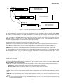
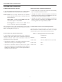
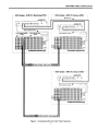
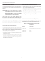
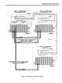
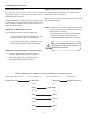
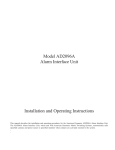
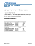
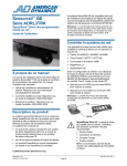
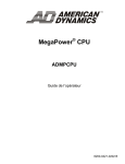
Model AD1024 MegaPower II
Central Processing Unit
Satellite Configuration
Installation Instructions
The manual describes the installation procedures for the American Dynamics AD1024 MegaPower II Central Processing Unit for
satellite configurations. Before installation, become familiar with all of the special features and warnings associated with this
equipment. Store this manual in a safe, convenient location for future reference.
This software/firmware is confidential to and is copyrighted by SENSORMATIC ELECTRONICS CORPORATION. It is not to
be copied or disclosed in any manner without the express written consent of SENSORMATIC. The software is furnished to the
purchaser under a license for use on a single system.
NOTE: Information furnished by SENSORMATIC is believed to be accurate and reliable. However, no responsibility is
assumed by SENSORMATIC for its use; nor for any infringements of other rights of third parties which may result from its use.
No license is granted by implications or otherwise under any patent or patent rights of SENSORMATIC.
Copyright 2000 by SENSORMATIC. All rights reserved.
AMERICAN
DYNAMICS
The installation of this product should be made by qualified
service personnel and should conform to all local codes.
CAUTION
RISK OF ELECTRIC SHOCK
DO NOT OPEN
The lightning flash with arrowhead
symbol, within an equilateral
triangle, is intended to alert the
user to the presence of uninsulated
"dangerous voltage" within the
product's enclosure that may be of
sufficient magnitude to constitute a
risk of electric shock to persons.
!
CAUTION: TO REDUCE THE RISK OF ELECTRIC SHOCK,
DO NOT REMOVE COVERS (OR BACK) .
NO USER-SERVICEABLE PARTS INSIDE.
REFER SERVICING TO QUALIFIED SERVICE PERSONNEL
WARNING
To reduce the risk of fire or shock hazard, do
not expose this product to rain or moisture.
Note: This equipment has been tested and found
to comply with the limits for a Class A digital
device, pursuant to part 15 of the FCC rules.
These limits are designed to provide reasonable
protection against harmful interference when
the equipment is operated in a commercial
environment. This equipment generates, uses,
and can radiate radio frequency energy and, if
not installed and used in accordance with the
instruction manual, may cause harmful
interference to radio communications.
Operation of this equipment in a residential
area is likely to cause harmful interference in
which case the user will be required to correct
the interference at his own expense.
Changes or modifications not expressly
approved by Sensormatic could void the user's
authority to operate the equipment.
!
The exclamation point within an
equilateral triangle is intended to
alert the user to the presence of
important operating and maintenance
(servicing) instructions in the
literature accompanying the product.
UNPACKING AND INSPECTION
Unpack carefully. This is an electronic product and should
be handled as such. Compare the items received with the
packing list with your order.
Be sure to save:
1. The shipping cartons and insert pieces. They are the
safest material in which to make future shipments of
the product.
2. The IMPORTANT SAFEGUARDS sheet.
3. These Installation and Operating Instructions.
)
MAINTENANCE
User maintenance of this unit is limited to external cleaning
and inspection. For specific recommendations refer to the
IMPORTANT SAFEGUARDS sheet packaged with this product.
INSTALLATION AND SERVICE
If you require information during installation of this
product or if service seems necessary, contact the
Sensormatic Repair and Service Department at (800)
442-2225. You must obtain a Return Authorization Number
and shipping instructions before returning any product for
service.
Do not attempt to service this product yourself. Opening or
removing covers may expose you to dangerous voltages or
other hazards. Refer all servicing to qualified personnel.
QA301E
Table of Contents
AD1024 Description ..............................................................
Satellite System Setup Overview...............................
1
1
System Configuration ............................................................
2
Network RS-232 Connections ...............................................
SITE -to- SITE RS-232 Communications .................
4
4
Network Video Connections ..................................................
Uni-directional Network Connection.........................
Bi-directional Network Connection...........................
Mixed Network Connection.......................................
6
6
8
10
System Installation.................................................................
Installation Preparation ..............................................
The Installation Map ..................................................
Power Sources............................................................
Mounting....................................................................
12
12
12
13
13
Component Connections........................................................
AD1024 Matrix Switching Bays................................
RS-232 Terminal Blocks............................................
Single 8-Pin Terminal Block................................
Dual 8-Pin Terminal Block ..................................
AD1981 Port Expander..............................................
AD2079 and AD2088 Series Keyboards ...................
AD2096 Alarm Interface Unit ...................................
AD2091 Code Generator ...........................................
Camera Connections ..................................................
Monitors.....................................................................
Program Monitor........................................................
Programming Computer.............................................
14
14
16
16
17
18
20
26
30
32
34
36
38
Additional Information ..........................................................
40
Specifications.........................................................................
Back Page
Satellite System Design Considerations
A. The current release of the AD1024 CPU software/firmware has the following restrictions. Use of these
features is not supported in the current release, and may lead to unexpected system operation.
1. The use of keyboard/user Priority levels is not supported (see Priority menu, System Programming and
Operating Instructions).
2. The Lockout feature is not supported for REMOTE cameras (see Camera Lockout programming, System
Programming and Operating Instructions).
3. Local alarm monitors can view LOCAL cameras only. If a LOCAL monitor is armed for an alarm contact
(and thus for display of a local camera), do not use that monitor to call REMOTE cameras for viewing.
4. The use of an AD1981 Port Expander with the AD1024 CPU RS-232 ports is not supported for satellite
data links.
5. The use of partitioning for keyboards, monitors, camera viewing and camera control is not supported.
However, keyboards can be partititioned from calling remote sites.
6. Ports used for satellite connections must be set at 9600 baud.
7. The use of an AD1981 Port Expander with the AD1024 CPU RS-232 ports may cause erroneous
information to be displayed in the keyboard CAMERA display, but will not affect system operation.
B. The adjustment of the on-screen display position and brightness (see Video Selection, page 2-3 and 2-4) is
augmented, as follows, from the instructions in the current AD1024 Matrix Switching Bays Installation
Manual. Reference page 17 of that manual, Video Output Module Horizontal, Vertical, and Brightness
Adjustment, for the following supplemental instructions.
1. Select the monitor to be adjusted.
2. Enter the keyboard codes “5 F2” (enter the number 5, then press the F2 key).
This selects the “Remote Site Title” on-screen display lines, as illustrated in upper lines of Figure 2-2
(page 2-4), for adjustment.
3. On the appropriate Video Output Module (VOM), select the video output position for this monitor (A. . D)
with the rotary switch (see AD1024 Matrix Switching Bays manual, page 17).
For the Remote Site Title lines, position the rotary switch with its white stripe opposite to the
monitor label (e.g., for monitor A, the white stripe is opposite the label “A” on the VOM).
4. Adjust the title vertical position using the VOM controls, as described in AD1024 Matrix Switching Bays
Manual, page 17 (the horizontal position and brightness is adjusted the same as the Called Camera Title,
below).
5. Enter the keyboard codes “6 F2” (enter the number 6, then press the F2 key).
This selects the “Called Camera Title” on-screen display lines, as illustrated in lower lines of Figures 21 and 2-2 (pages 2-3 and 2-4), for adjustment.
6. On the appropriate Video Output Module (VOM), select the video output position for this monitor (A. . D)
with the rotary switch (see AD1024 Matrix Switching Bays manual, page 17).
For the Called Camera Title lines, position the rotary switch with its white stripe facing the monitor
label (e.g., for monitor A, the white stripe must be facing label “A” on the VOM).
7. Adjust the horizontal position, vertical position, and brightness of this title using the VOM controls, as
described in the AD1024 Matrix Switching Bays manual, page 17.
8. Repeat steps 1 through 7 for each monitor of the VOM and for each VOM, as required.
DESCRIPTION
AD1024 Bays
AD1024 CPU
DATA
POWER
1024 Local Video Inputs
128 Local Video Outputs
Site 1
AD
MEGAP OWER II
WXYZ
F EDC
BA9 8
7 6 5 4
3 2 1 0
S YSTEM CPU
AD1024 Bays
AD1024 CPU
DATA
POWER
1024 Local Video Inputs
128 Local Video Outputs
Site 2
AD
MEGAP OWER II
WXYZ
F EDC
BA9 8
7 6 5 4
3 2 1 0
S YSTEM CPU
AD1024 Bays
AD1024 CPU
DATA
POWER
Site 3
AD
MEGAP OWER II
WXYZ
F EDC
BA9 8
7 6 5 4
3 2 1 0
S YSTEM CPU
1024 Local Video Inputs
128 LocalVideo Outputs
Figure 1 - Three-Site AD1024 MegaPower II Satellite System
AD1024 DESCRIPTION
The AD1024 MegaPower II System used in a satellite configuration is a CCTV surveillance system for multiple control SITES,
with multiple video inputs, multiple video outputs, and multiple control stations at each SITE. The AD1024 Central Processing
Unit (CPU) is the controlling unit for each individual SITE in a Satellite System. Each SITE is a complete CCTV surveillance
system, providing both LOCAL (independent) control of all resources connected to the AD1024 CPU at that SITE, and
REMOTE control of certain resources of other SITES within the Satellite network. Individual AD1024 SITES are
interconnected by data links (RS-232 communications) and by video trunk lines.
Throughout this manual, AD1024 System functions reference the following terms:
SITE refers to a single AD1024 CPU of a Satellite network and the resources that are directly connected and accessible to it.
LOCAL refers to features that are accessible within a single SITE by a keyboard attached to that SITE’s AD1024 CPU.
REMOTE refers to features of other AD1024 SITES in a Satellite network accessible from a particular AD1024 SITE.
The AD1024 MegaPower II System incorporates networking capabilities permitting a maximum of 16 separate AD1024 SITES
within one Satellite network. Each individual SITE is capable of controlling a maximum of 1024 local video inputs, such as
cameras, and a maximum of 128 video outputs, such as monitors, from a maximum of 36 operator keyboards.
SATELLITE SYSTEM SETUP OVERVIEW
For satellite system installations, specific procedures are required, at each SITE in the satellite network, before any network
functions can be performed.
Depending on the individual SITE connections (uni-directional, bi-directional, or mixed), each site may be either a Source SITE,
a Receiver SITE, or a Receiver/Source SITE.
• SITE refers to a single AD1024 CPU in a satellite network and the resources that are directly connected and accessible to it.
Source SITE - a satellite network SITE which provides video trunk outputs to other SITES.
Receiver SITE - a satellite network SITE which receives video trunk inputs from other SITES.
Receiver/Source SITE - a satellite network SITE which sends and receives video trunk signals to and from other SITES.
• LOCAL refers to operating features that are accessible within a single SITE by the keyboard attached to that SITE’S AD1024
CPU.
• REMOTE refers to programming features of other AD1024 SITES in a satellite network that are accessible from the LOCAL
AD1024.
NOTE: For more information regarding LOCAL and REMOTE features, refer to the AD1024 CPU System Programming and
Operating Instruction Manual.
1
SYSTEM CONFIGURATION
SYSTEM CONFIGURATION
Each AD1024 SITE operates as a fully independent, standalone, surveillance system capable of controlling a maximum
1024 video inputs (local cameras, remote video input trunks,
and other video sources) and 128 video outputs (monitors,
remote video output trunks, and video tape recorders) from a
maximum of 36 operator control keyboards.
A Level 5 System has 20 Video Output Modules (VOMs)
loaded into the 1024 Matrix Switcher/Controller bays
providing a maximum of 80 video outputs.
A Level 6 System has 24 Video Output Modules (VOMs)
loaded into the 1024 Matrix Switcher/Controller bays
providing a maximum of 96 video outputs.
A minimum AD1024 installation consists of a Level 1 system,
capable of controlling a maximum 1024 video inputs with a
maximum of 16 video outputs. Levels are determined by the
number of Video Output Modules (VOMs) loaded into the
standard AD1024 Matrix Switcher/Controller bay.
A Level 7 System has 28 Video Output Modules (VOMs)
loaded into the 1024 Matrix Switcher/Controller bays
providing a maximum of 112 video outputs.
A Level 8 System has 32 Video Output Modules (VOMs)
loaded into the 1024 Matrix Switcher/Controller bays
providing a maximum of 128 video outputs.
A Level 1 System has four Video Output Modules (VOM)
loaded into the 1024 Matrix Switcher/Controller bay providing
a maximum of 16 video outputs.
A Level 2 System has eight Video Output Modules (VOMs)
loaded into the 1024 Matrix Switcher/Controller bays
providing a maximum of 32 video outputs.
A Level 3 System has 12 Video Output Modules (VOMs)
loaded into the 1024 Matrix Switcher/Controller bays
providing a maximum of 48 video outputs.
A Level 4 System has 16 Video Output Modules (VOMs)
loaded into the 1024 Matrix Switcher/Controller bays
providing a maximum of 64 video outputs.
Video
Output
Modules
System
Video
Outputs
(Maximum)
System
Video
Inputs
(Maximum)
Level 1
Level 2
Level 3
System Level
Level 4
Level 5
Level 6
Level 7
Level 8
4
8
12
16
20
24
28
32
16
32
48
64
80
96
112
128
1024
2
NETWORK RS-232 CONNECTIONS
NETWORK RS-232 CONNECTIONS
SITE -to- SITE RS-232 Network Connection
SITE -to- SITE RS-232 Communications
SITE -to- SITE network connections using the RS-232
protocol require one 2113-0019-01 terminal block per AD1024
CPU (see Figure 3).
Forming a network of two or more AD1024 SITES requires an
individual RS-232 communication link between each AD1024
CPU in the network.
Table 2 lists the terminal block pin definitions.
NOTE: SITE refers to a single AD1024 CPU in a satellite
network and the resources that are directly connected
and accessible to it.
SITE -to- SITE refers to multiple AD1024 CPUs
networked together.
Terminal
Block
Signal
The AD1024 CPU sends and receives RS-232 signals from
SITE to SITE via ten 8-pin modular RJ45 control ports.
N/C
1
NC
Shield
2
NC
N/C
3
NC
SITE -to- SITE RS-232 Cable Requirements
Receive Data
4
RCD
The maximum RS-232 cable length between sites is 1000 ft.
(330 m) using three-wire, 18AWG, shielded cable (Belden
8770 or equivalent) computer grade cable and HP0047
terminal blocks.
Transmit Data
5
XMIT
N/C
6
NC
Ground
7
GND
N/C
8
NC
Table 2 - 2113-0019-01 Pin Definitions
Table 1 lists the cable gauge-vs-length requirements for proper
operation of an RS-232 communication link between AD1024
CPUs.
Distance
Wire Gauge
AD1024 CPU
1000ft/305m
18AWG/shield
RS-232
Signal
Code
NOTE: The shield wire of the SITE -to- SITE RS-232
communication cable is only connected at one end,
with no preference given to either end (see Figure 3).
Table 1 - Cable Requirements for SITE -to- SITE RS-232
Communications
Unit
Block
Pin #
Table 3 lists the SITE -to- SITE RS-232 connections between
AD1024 CPUs.
NOTE: Distances greater than 1000 feet (305m) between
AD1024 CPUs require the use of either asynchronous
line drivers over dedicated cables, short-haul modems
over dedicated phone lines, or dial-up modems over
conventional telephone lines.
Table 3 - SITE -to- SITE RS-232 Connections
SITE 1
SITE 2
SITE 3
SITE 4
SITE 5
SITE 6
SITE 7
SITE 8
SITE 9
SITE 10
Terminal
Block Pin#
Terminal
Block Pin#
Terminal
Block Pin#
Terminal
Block Pin#
Terminal
Block Pin#
Terminal
Block Pin#
Terminal
Block Pin#
Terminal
Block Pin#
Terminal
Block Pin#
Terminal
Block Pin#
2
N/C
N/C
N/C
N/C
N/C
N/C
N/C
N/C
N/C
4
5
5
5
5
5
5
5
5
5
5
4
4
4
4
4
4
4
4
4
7
7
7
7
7
7
7
7
7
7
4
NETWORK RS-232 CONNECTIONS
AD1024 System - SITE #1
AA
A
A
AAAAAAAAAA
A
AAAA
A
A
A
DATA
LINE
1
2113-0019-01
Terminal Block
1
2
3
4
2
3
5
10
8
7
2
7
6
3
5
4
3-Wire, 18 AWG,
Shielded Cable
A
A
A
A
A
A
A A A
AAA
A
A
A
6
5
AA
AA
A
A
4
3
9
9
6
8
8
2
7
7
1
PRO G M O N
6
6
7
3
5
5
120V
60Hz
8
DATA LI NE
120V
60Hz
4
4
1
4
PO RTS
1
8
5
3
6
2
2
1
7
2
1
1
AAA
AA
A
8
DATA LI NE
Shield
2
PROG
MON
AD1024 CPU
Cable 6003-0047-02
2113-0019-01
Terminal Block
PORT
S
1
10
PO RTS
2
1
2
3
4
5
6
7
PRO G M O N
120V
60Hz
8
9
10
AD1024 CPU
AD1024 CPU
AD1024 System - SITE #2
AD1024 System - SITE #3
Figure 3 - SITE-to-SITE AD1024 CPU RS-232 CONNECTIONS
5
NETWORK VIDEO CONNECTIONS
NETWORK VIDEO CONNECTIONS
Uni-Directional Network Connection
SITE-to-SITE Video Trunk Recommendations
A uni-directional network between two or more SITES
requires a minimum of one video trunk between each SITE.
• Number both ends of each video trunk with cloth marking
tape or a similar identification method.
• Although not required, American Dynamics recommends
beginning video trunk connections at the highest level of the
Source SITE Video Output Modules (VOM).
NOTE: SITE refers to a single AD1024 CPU in a satellite
network and the resources that are directly connected
and accessible to it.
• Although not required, American Dynamics recommends
routing video trunk connections to the highest level of the
Receiving SITE Video Output Modules (VIM).
Source SITE - a satellite network SITE which sends
video trunk outputs to other SITES.
Receiving SITE - a satellite network SITE which
receives video trunk inputs from other SITES.
The video trunks carry video signals from a Source SITE
AD1024 Matrix Switching Bay to a Receiving SITE AD1024
Matrix Switching Bay (see Figure 4).
Uni-Directional Network Video Cable Requirements
All video trunks require a high grade, 75Ω, video cable with
BNC connectors. Table 4 lists video cable -vs- length
requirements for proper video transmission between sites.
SITE-to-SITE Video Trunk Considerations
Table 4 - Cable Requirements for Network Video
Transmission
A typical SITE-to-SITE uni-directional video connection
consists of eight video trunks between each Source SITE and
each Receiver SITE. More or less video trunks can be used
depending on the user's application.
Distance
Video Cable
1000ft/305m
RG-59U (Belden 8241 or equivalent)
• Determine the number of video trunks required between all
SITES in the network prior to installing the trunks.
1500ft/457m
RG-6
2000ft/610m
RG-11
• Determine the maximum number of different video inputs
that require simultaneous viewing from each Source SITE to
this Receiving SITE and reserve one video input terminal at
this SITE for each video input.
6
NETWORK VIDEO CONNECTIONS
Bi-Directional Network Connection
SITE-to-SITE Video Trunk Recommendations
A bi-directional network between two or more SITES requires
a minimum of two video trunks between each SITE (see
Figure 5).
• Number both ends of each video trunk with cloth marking
tape or a similar identification method.
• Although not required, American Dynamics recommends
beginning video trunk connections at the highest level of the
Source SITE Video Output Modules (VOM).
NOTE: SITE refers to a single AD1024 CPU in a satellite
network and the resources that are directly connected
and accessible to it.
• Although not required, American Dynamics recommends
routing video trunk connections to the highest level of the
Receiving SITE Video Output Modules (VIM).
Receiver/Source SITE - a satellite network SITE
which sends and receives video trunk signals.
Video trunks carry video signals from the first
Receiver/Source SITE AD1024 Matrix Switching Bay to the
second Receiver/Source SITE AD1024 Matrix Switching Bay.
Bi-Directional Network Video Cable Requirements
Video trunks carry video signals from the second
Receiver/Source AD1024 Matrix Switching Bay to the first
Receiver/Source AD1024 Matrix Switching bay (see Figure 5).
All video trunks require a high grade, 75Ω, video cable with
BNC connectors. Table 5 lists video cable -vs- length
requirements for proper video transmission between sites.
Table 5 - Cable Requirements for Network Video
Transmission
SITE-to-SITE Video Trunk Considerations
A typical SITE-to-SITE bi-directional video connection may
consist of eight video trunks, in each direction, from each
Receiver/Source SITE to each Receiver/Source SITE (see
Figure 5). More or less video trunks can be used between
sites, depending on the user's application.
• Determine the number of video trunks required between all
SITES in the network.
• Determine the maximum number of different video inputs
that require simultaneous viewing from each Source SITE to
this Receiving SITE and reserve one video input terminal at
this SITE for each video input.
8
Distance
Video Cable
1000ft/305m
RG-59U (Belden 8241 or equivalent)
1500ft/457m
RG-6
2000ft/610m
RG-11
NETWORK VIDEO CONNECTIONS
Mixed Network Connection
SITE-to-SITE Video Trunk Recommendations
A mixed direction network consists of both uni-directional
AD1024 SITES and bi-directional AD1024 SITES (see Figure
6).
• Number both ends of each video trunk with cloth marking
tape or a similar identification method.
• Begin video trunk connections at the highest level of the
Source SITE Video Output Modules (VOM).
A mixed direction network between two or more SITES
requires a minimum of two video trunks between each SITE.
• Route the video trunk connections to the highest level of the
Receiving SITE Video Output Modules (VIM).
NOTE: SITE refers to a single AD1024 CPU in a satellite
network and the resources that are directly connected
and accessible to it.
Mixed Network Video Cable Requirements
Source SITE - a satellite network SITE which sends
video trunk signals to other SITES.
Receiving SITE - a satellite network SITE which
receives video trunk signals from other SITES.
All video trunks require a high grade, 75Ω, video cable with
BNC connectors. Table 6 lists video cable -vs- length
requirements for proper video transmission between SITES.
Receiver/Source SITE - a satellite network SITE
which sends and receives video trunk signals.
Table 6 - Cable Requirements for Network Video
Transmission
Video trunks carry video signals from the first
Receiver/Source SITE AD1024 Matrix Switching Bay to the
second Receiver/Source SITE AD1024 Matrix Switching Bay.
Distance
Video Cable
1000ft/305m
RG-59U (Belden 8241 or equivalent)
Video trunks carry video signals from the second
Receiver/Source AD1024 Matrix Switching Bay to the first
Receiver/Source AD1024 Matrix Switching bay (see Figure 6).
1500ft/457m
RG-6
2000ft/610m
RG-11
SITE-to-SITE Video Trunk Considerations
A typical SITE-to-SITE mixed direction video connection may
consist of eight video trunks, in each direction, from each
Receiver/Source SITE to each Receiver/Source SITE (see
Figure 6). More or less video trunks can be used between
sites, depending on the user's application.
• Determine the number of video trunks required between all
SITES in the network.
• Determine the maximum number of different video inputs
that require simultaneous viewing from each Source SITE to
this Receiving SITE and reserve one video input terminal at
this SITE for each video input.
10
SYSTEM INSTALLATION
SYSTEM INSTALLATION
Installation Preparation
Only qualified service personnel familiar with all local
building codes should attempt this installation. Safeguards
must be taken to avoid unintentional operation by employees
and maintenance personnel working about the premises.
Before starting the installation of a AD1024 System, become
familiar with the specifications of the particular system(s).
Complete the installation and testing of each AD1024 System
before connecting into a network. Any possible wiring or
installation problems will be magnified many times by the
complexity of the network.
•Will the system be connected into a network?
Once a system is tested and operating satisfactorily, it can then
be safely brought into the network.
•How many video input sources does the system have?
In particular:
Will the network connection be uni-directional (one-way)?
Will the network connection be bi-directional (two-way)?
Will the network connection be a mixed configuration?
Video input sources include LOCAL cameras and video
input trunks from Source SITES.
NOTE: The maximum number of video inputs per AD1024
System is 1024.
•How many video output sources does the system have?
Video output sources include LOCAL monitors and video
output trunks to Receiver SITES.
NOTE: The maximum number of video outputs per AD1024
System is 128
Determine the System Level (refer to page 2).
•What system accessories are being installed?
After these questions are answered, prepare an
Installation Map for each System.
The Installation Map
The information on each Installation Map should include:
• Where all System equipment will be mounted
• Where equipment wire busses will be routed
• Where video input trunks will be routed
• Where video output trunks will be routed
• An alpha-numeric coding scheme for the different wiring
categories (Video IN trunks, Video OUT trunks, alarms, data
lines, etc).
12
SYSTEM INSTALLATION
Power Sources
Control Port Connections
The AD1024 CPU is configured for a 120V, 50/60 Hz primary
power source. The AD1024CPU-1 is configured for a 230
VAC, 50/60 Hz power source. The 120 VAC units are supplied
with a pendant 3-wire cord and plug for mating to the primary
source outlet. The 230 VAC units are supplied with a Eurostyle IEC 320 type inlet. A suitable detachable cord should be
connected between the IEC 320 inlet and the power source.
The cord should conform to all national and local use code
requirements.
Ten 8-pin, modular RJ-45 control ports, labeled PORTS 1
through 10, are provided on the rear panel for all RS-22 control
communications (see Figure 7).
Each of the ten control ports may be configured for a specific
use (such as keyboard, alarm, video loss, printer, or terminal).
• The AD1024 CPU receives all control and alarm inputs
from keyboards, external computers, alarm interface units,
or video loss detectors via the control ports.
CAUTION
!
• The AD1024 CPU transmits all ASCII-coded, printable
Do not physically connect the AD1024 CPU to
the power source until all system connections
are complete.
messages to a serial RS-232 printer via the control ports.
• System setup data can be uploaded and downloaded from an
external computer via an RS-232 control port using the
optional PC-based software package, AD1024W16
Mounting
The AD1024 CPU is designed and manufactured for
installation into a standard 19-inch EIA rack (see Figure 7).
The AD1024 CPU unit has a height of one rack unit (1.75inches).
Each control port is configured to receive and transmit
commands via the RS-232 protocol, and is programmable for
RS-232 baud rate, data bits, stop bits, and data parity.
As shipped, all AD1024 CPU control ports are configured for
keyboard use at a 1200Kbps baud rate, 8 data bits, 1 stop bit,
and no parity.
CAUTION
!
Each AD1024 CPU requires a minimum of one
rack unit clearance above the top and below the
bottom for adequate ventilation.
19"/482.6mm
DATA
POWER
AD
MEGAPO W ER II
W XYZ
FED C
DATA LINE
B A 98
7654
3210
SYSTEM CPU
PROG MON
PORTS
DO NOT CONNECT TO TELEPHONE CIRCUITS
1.75"
44.5mm
120V
60Hz
1
2
1
2
3
4
5
!
6
7
8
9
Figure 7 - AD1024 Front and Rear Panel Dimensions
13
10
COMPONENT CONNECTIONS
COMPONENT CONNECTIONS
DATA LINE1 Connections
AD1024 Matrix Switching Bays
Table 7 lists the DATA LINE1 and DATA LINE2 connections
to the different Levels of the AD1024 Matrix Switching Bays.
Two data line output terminals on the rear panel of the
AD1024 CPU, labeled DATA LINE1 and DATA LINE2,
transmit instructions to the AD1024 Matrix Switching Bays.
1. Connect the AD1024 CPU DATA LINE1 OUT terminal
to the DATA LINE IN terminal of the first AD1024
Switching Bay unit of Level 1 (see Figure 8).
DATA LINE 1 routes the AD1024 CPU control signals to
pan/tilt, lens, and auxiliary functions at suitably equipped
sites, up to a maximum of 1024 sites. DATA LINE1 also
routes the matrix switching information for Level 1 through
4 AD1024 Switching Bay video outputs 1 to 64 (see
Figure 8).
2. Daisy-chain DATA LINE1 through the Level 1 AD1024
Switching Bay units by connecting the OUT terminal of
the first AD1024 Switching Bay unit to the IN terminal
of the next Level 1 AD1024 Switching Bay in.
3. Continue daisy-chaining DATA LINE1 through the
AD1024 Switching Bay units of Levels 1, 2, 3, and 4.
DATA LINE2 routes the matrix switching information for
Level 5 through 8 video outputs 65 to 128.
DATA LINE1 and DATA LINE2 are daisy-chained through
the input and output terminals of the AD1024 Switching Bays,
depending on the system level configuration (see Figure 8).
DATA LINE2 Connections
1. Connect the AD1024 CPU DATA LINE2 OUT terminal
to the DATA LINE IN terminal of the first AD1024
Switching Bay of Level 5 (see Figure 8).
DATA LINE Cable Requirements
2. Daisy-chain DATA LINE2 through the Level 5 AD1024
Switching Bay units by connecting the OUT terminal of
the first AD1024 Switching Bay unit to the IN terminal
of the next AD1024 Switching Bay unit.
DATA LINE1 and DATA LINE2 require 75Ω, RG-59U video
cable (Belden 8241 or equivalent) with BNC connectors.
3. Continue daisy-chaining DATA LINE2 through the
AD1024 Switching Bay units of Levels 5, 6, 7, and 8.
Table 7 - DATA LINE1 and DATA LINE2 -to- AD 1024 Matrix Switching Bay Levels
DATA LINE1
Video Inputs
Video Outputs
Level 1 Matrix Switching Bays
1024
16
Level 2 Matrix Switching Bays
“
“
32
Level 3 Matrix Switching Bays
“
“
48
Level 4 Matrix Switching Bays
“
“
64
Level 5 Matrix Switching Bays
1024
80
Level 6 Matrix Switching Bays
“
“
96
Level 7 Matrix Switching Bays
“
“
112
Level 8 Matrix Switching Bays
“
“
128
DATA LINE2
14
COMPONENT CONNECTIONS
RS-232 Terminal Blocks
Single 8-Pin Terminal Block
Single 8-Pin Terminal Block Cable Requirements
The Single 8-pin terminal block 2113-0019-01
(see Figure 9) connects external RS-232 devices
to the AD1024 CPU's RS-232 control ports.
8-pin terminal blocks require an 18AWG, shielded,
computer grade cable between the terminal block and the
particular RS-232 device connecting to it.
Consult the installation manual of the external RS-232 device
for its pin and signal definitions.
Table 9 lists the cable gauge-vs-length requirements for proper
operation of the AD1024 CPU and the associated RS-232
device.
Table 8 lists the 8 pin terminal block pin definitions.
Table 9 - Cable Requirements for Single 8-Pin Terminal Blocks
Unit
Distance
Table 8 - Single Terminal Block Pin Definitions
Function
Terminal
Block
Pin #
RS-232
Signal
No Connection
Shield
No Connection
Receive Data
Transmit Data
No Connection
Ground
No Connection
1
2
3
4
5
6
7
8
NC
NC
NC
RCD
XMIT
NC
GND
NC
Wire Gauge
(maximum)
HP0047
Terminal
Block
1000ft/305m
18AWG Shielded
NOTE: Where the distance is over 1000 feet, link the RS-232
devices with either asynchronous line drivers over
dedicated cables, short-haul modems over dedicated
phone lines, or dial-up modems over conventional
telephone lines.
Single 8 pin
Terminal Block
4
5
3
6
2
7
1
8
Figure 9 - 8 Pin Terminal Block
16
COMPONENT CONNECTIONS
Dual 8-Pin Terminal Block
Power Connection
The dual 8-pin terminal block 2113-0020-01 connects
AD2079 and AD2088 Series keyboards to the AD1024
RS-232 control ports (see Figure 10).
The dual terminal block power supply is provided with the
AD2079 and AD2088 Series Keyboards. Refer to page 20 for
Keyboard information.
Table 10 lists the dual terminal block pin definitions
!
Table 10 - Terminal Block J1 (Keyboard) Side Pins
Function
Transformer Power In
Shield/Ground
RS-232 RCD, RS-422 R +
RS-232 XMIT, RS-422 T +
GND (Ground)
Transformer Power In
Terminal
Block
Pin #
1
2
4
5
7
8
Dual
Terminal Block
5
4
4
XMIT RCD
3
6
3
6
2
2
7
GND
5
1
1
8
7
8
J1
J2
Figure 10 - Dual Terminal Block
17
COMPONENT CONNECTIONS
AD1981 Port Expander
Connecting the AD1981 to the AD1024 CPU
The AD1981 Port Expander increases the maximum number of
system input devices by connecting four RS-232 devices
through one AD1024 RS-232 port (see Figure 11).
The AD1981 output port connects to one of the AD1024
CPUs RS-232 ports through an 8 pin terminal block (21130019-01) via the modular cable 6003-0047-02 (see Figure 12).
Table 11 lists the pin definitions of each AD1981 RS-232 port.
NOTE: Use 3-conductor, shielded, Belden 8770 or equivalent
cable for all connections unless otherwise specified.
Table 11 - AD1981 RS-232 Port Pin Definitions
Pin
1
2
3
4
5
6
7
8
9
1. Connect the AD1981 output port Pin 3 (XMIT) to the
8 pin terminal block Pin 4 (RCD).
Definition
Shield
No Connection
Transmit Data
Receive Data
Ground
No Connection
DSR
DTR
No Connection
2. Connect the AD1981 output port Pin 4 (RCD) to the
8 pin terminal block Pin 5 (XMIT).
3. Connect the AD1981 output port Pin 5 (GND) to the
8 pin terminal block Pin 7 (GND).
4. Connect the shield wire to Pin 2 of the 8 pin terminal block.
NOTE: Do Not Connect the Opposite Shield Wire to the
AD1981 Output Port.
The AD1981 has five RS-232 ports (see Figure 11).
5. Connect the 8 pin terminal block to an AD1024 CPU
control port with a modular RS-232 cable.
One RS-232 output port (labeled To CPU) connects
the AD1981 to the AD1024 CPU.
Four RS-232 ports (labeled KBD a, KBD b, KBD c,
and KBD d) connect system keyboards to the
AD1981 Port Expander.
All AD1981 RS-232 ports connect the keyboard input through
9-pin D-type connectors as follows:
KBD a
KBD b
KBD c
KBD d
Keyboard Input Port A
Keyboard Input Port B
Keyboard Input Port C
Keyboard Input Port D
to
CPU
KBD - d KBD - c KBD - b KBD - a
Figure 11 - AD1981 Port Expander
18
COMPONENT CONNECTIONS
DATA LINE
1
2
A
A
A
PORTS
1
2
3
6003-0047-02 Cable
2113-0019-01
Terminal Block
4
5
PROG MON
120V
6 0 HZ
6
7
8
9
10
AD1024 CPU
8
1
2
7
6
3
4
5
RCD XMIT
GND
Three-Wire, 18 AWG,
Shielded Cable
CPU Port
1
2
6
to
CPU
3
7
4
8
5
9
KBD - d KBD - c KBD - b KBD - a
AD1981 Port Expander
Figure 12 - AD1981 Port Expander -to- AD1024 CPU
19
COMPONENT CONNECTIONS
AD2079 and AD2088 Series Keyboards
Keyboards Within Seven Feet of CPU
The AD2079 and AD2088 Series keyboards are used to input
operational functions to the AD1024 system.
Connecting a keyboard to the AD1024 CPU where the distance
between the keyboard and the AD1024 CPU is less than seven
feet requires the use of one dual terminal block (see Figure
13).
Two installation procedures exist for the keyboards.
One procedure applies to keyboards installed within
seven feet of the AD1024 CPU.
Table 12 lists the connections between the keyboard, the
dual terminal block, and the AD1024 CPU.
A second procedure applies to keyboards installed
beyond seven feet from the AD1024 CPU (see page 22).
Keyboard Cable Requirements
Between the Keyboard and dual terminal block:
Use 6003-0047-02 Modular Cable w/RJ-45 jacks.
Jumpers between the J1 side of the dual terminal block and
the J2 side of the terminal block:
Use 22AWG wire (supplied with the dual
terminal block).
Between the J2 side of the HP0082 terminal block and the
AD1024 CPU:
Use 6003-0047-02 Modular Cable w/RJ-45 jacks.
Table 12 - Keyboard Connections (Within Seven Feet of AD1024 CPU)
J1 (Left-Hand) Side of DualTerminal Block
J2 (Right-Hand) Side of Dual Terminal Block
Pin Number
Terminal Functions
Pin Number
1
Transformer Power IN
N/C
2
Shield/Ground
N/C
3
Terminal Functions
N/C
4
RS-232 Receive
5
RS-232 Transmit
5
RS-232 Transmit
4
RS-232 Receive
6
N/C
7
Ground
7
8
Transformer power IN
N/C
RJ-45 Jack
to Keyboard
RJ-45 Jack
20
Ground
to AD1024 RS-232 port
COMPONENT CONNECTIONS
DATA LINE
A
A
A
A
A
A
AAAAAAAAAA
A
A
A
A
A
A
AA
A
A
A
A
AA
AAAAAAAAAA
A
A
AA
PORTS
PROG MON
120V
6 0 HZ
1
2
1
2
3
4
5
6
7
8
9
10
AD1024 CPU
6003-0047-02 Cable
RCD
XMIT
Jumper Wire
5
Wall
Transformer
GND
4
5
3
6
2
7
1
8
3
6
7
8
2
1
J1
6003-0047-02 Cable
4
2113-0020-01
TERMINAL BLOCK
J2
AD2088 Keyboard
Figure 13 - AD2088 Keyboard -to- AD1024 CPU (Keyboard Within Seven Feet of CPU)
21
COMPONENT CONNECTIONS
Keyboards Greater Than Seven Feet from AD1024 CPU
Keyboard Cable Requirements
Connecting an keyboard to the AD1024 CPU where the
distance between the keyboard and the AD1024 CPU is
greater than seven feet requires the use of one dual
terminal block and one single terminal block (see Figure 14).
Between keyboard and dual terminal block:
Use 6003-0047-02 Modular Cable w/RJ-45 jacks.
Table 13 lists the connections between the keyboard, the
dual terminal block, the single terminal block, and the
AD1024 CPU.
Between the dual terminal block and the single terminal
block:
Use three-wire, 18AWG, shielded cable (Belden
8770 or equivalent).
NOTE: Do Not connect the shield wire to Pin 2 of the
dual terminal block.
Between the J2 side of the dual terminal block and the
AD1024 CPU:
Use 6003-0047-02 Modular Cable w/RJ-45 jacks.
Table 13 - Keyboard Connections (Greater than Seven Feet from the AD1024 CPU)
Single Terminal Block
J1 (Left-Hand) Side of Dual Terminal Block
Pin Number
Terminal Functions
Pin Number
1
Transformer Power IN
N/C
2
Shield/Ground
2
3
RS-422 R - (Neg)
N/C
4
5
RS-232 Transmit
4
RS-232 Receive
6
RS-232 Receive
(RS-422 R + (Pos)
RS-232 Transmit
(RS-422 T + (Pos)
RS-422 T - (Neg)
7
Ground
7
8
Transformer power IN
N/C
RJ-45 Jack
to Keyboard
RJ-45 Jack
5
Terminal Functions
Shield/Ground
N/C
22
Ground
to AD1024 RS-232 port
COMPONENT CONNECTIONS
DATA LINE
1
2
A
A
A
PORTS
1
2
3
6003-0047-02 Cable
2113-0019-01
Terminal Block
1
4
2
PROG MON
120V
6 0 HZ
5
6
7
AD1024 CPU
8
5
RCD XMIT
GND
5
4
3
6
2
7
1
8
8
A
A
A
A
J1
6003-0047-02 Cable
4
3
6
7
10
6
4
5
9
7
3
Wall
Transformer
8
2
1
2113-0020-01
Terminal Block
J2
AD2088 Keyboard
Figure 14 - AD2088 Keyboard -to- AD1024 CPU (Keyboard Greater Than Seven Feet from CPU)
23
COMPONENT CONNECTIONS
AD2078 Series Keyboard to AD1981 Port Expander
AD2078 Series Keyboard to AD1981 Cable Requirements
The AD1981 Port Expander increases the number of AD1024
system input keyboards from 10 to a maximum of 40. A
dual terminal block connects each AD2078 Series
keyboard to the AD1981 Port Expander (see Figure 15).
AD2078 Series keyboards connect to the dual terminal
blocks via a modular cable 6003-0047-02 (Belden 8770
or equivalent) with RJ-45 jacks.
The dual terminal blocks require an 18AWG, 3-conductor,
shielded cable between the terminal block and the AD1981
Port Expander.
Table 14 lists the connection pin definitions between the
dual terminal block and the AD1981 Port Expander.
Table 15 lists the cable gauge-vs-length requirements for
proper operation of the AD2078 Series Keyboard and the
AD1981 Port Expander.
Table 15 - Cable Requirements for AD1981 Port Expander
Unit
Distance
Wire Gauge
(Maximum)
AD1981
Port
Expander
1000ft/305m
18AWG Shielded
Table 14 - AD2078 to AD1981 Port Expander Connections
Dual Terminal Block
Pin #
AD1981 Port Expander (KBD port a, b, c, or d)
Definition
(to Wall Transformer)
Pin #
Definition
1
N/C
2
N/C
1
Transformer Power IN
2
Shield
3
N/C
4
RS-232 Receive (RCD)
3
Transmit Data
5
RS-232 Transmit (XMIT)
4
Receive Data
6
N/C
7
Ground (GND)
5
Ground
8
Transformer Power IN
to Wall Transformer
J1
RJ-45 Jack
to AD 2078 Keyboard
7
N/C
8
N/C
9
N/C
24
COMPONENT CONNECTIONS
CPU Port
AD1981 Port Expander
to
CPU
KBD - d
KBD - b KBD - a
KBD - c
1
2
6
3
7
4
8
5
9
Three-Wire, 18 AWG,
Shielded Cable
Shield
GND XMIT RCD
5
Wall
Transformer
5 4
4
3
6
2
7
1
8
3
6
7
8
AA
AA
AA
AA
J1
6003-0047-02 Cable
2
1
2113-0020-01
Terminal Block
J2
AD2088 Keyboard
Figure 15 - AD2088 Keyboard -to- AD1981 Port Expander Connection
25
COMPONENT CONNECTIONS
AD2096 Alarm Interface Unit
AD2096 Connection (Greater Than Seven Feet from CPU)
The AD2096 Alarm Interface Unit (AIU) provides
simultaneous callup of a camera site to a monitor when a
related alarm input is activated.
Two terminal blocks (2113-0019-01) are required for this
connection procedure (see Figure 18).
Table 16 lists the required connections between the AD2096
AIU and an AD1024 CPU.
A single AD2096 unit is capable of receiving and interpreting
64 alarm inputs. Cascading multiple AD2096 Alarm Interface
Units expands the AD1024 System's alarm capacity to a
maximum 1024 alarm inputs.
NOTES: Use three-wire, 18AWG, shielded cable (Belden
8770 or equivalent) for the following connections
unless otherwise specified.
AD2096 AIU to AD1024 CPU Connection
Two installation procedures exist for the AD2096 AIU:
The maximum distance between the terminal blocks
must not exceed 1000 feet using three-wire,
18 AWG shielded cable, Belden 8770 or equivalent.
The first procedure applies to AD2096 AIU units
installed within seven feet of the AD1024 CPU.
The second procedure applies to AD2096 AIU units
installed beyond seven feet from the AD1024 CPU.
!
Refer to the AD2096 Alarm Interface Unit
Installation and Operation manual for
detailed setup procedures.
AD2096 AIU Connection (Within Seven Feet of the CPU)
1. Connect a modular cable to the COM OUTPUT
port on the AD2096 AIU rear panel (see Figure 17).
2. Connect the opposite end of the modular cable to
the designated AD1024 CPU control port.
Table 16 - AD2096 AIU -to- AD1024 CPU Connection (Distance Greater Than Seven Feet)
AD2096 Alarm Interface Unit
COM OUTPUT Port
8-Pin Terminal Block #1
8-Pin Terminal Block #2
RJ-45 jack
RJ-45 jack
Pin #1
N/C
Pin #2
Cable Shield
Pin #3
N/C
Pin #4
Pin #4
Pin #5
Pin #5
Pin #6
N/C
Pin #7
Pin #7
Pin #8
N/C
26
AD1024 CPU
RJ-45 Control Port
COMPONENT CONNECTIONS
AA
AA
A A
AAAAA
AAAA
A
A A
DATA
LI NE
1
PORTS
2
1
2
3
4
5
6
PROG
MON
7
8
9
10
AD1024 CPU
S ELECT
ON
O FF
ABCDEFG H
POWER
A
A
A
A
25
30
ON
ALARM
7
12
A
A
A
26
A
27
28
8
A
A
A
29
9
A
31
36
A
32
10
11
A
33
13
18
A
34
14
A
A
35
15
A
37
42
16
A
38
A
39
17
19
24
A
40
20
41
21
22
23
PRGM
A
A
A
A
43 44
48
45
A
A
A
A
A
46
47
O FF
ABCDEFG H
C
O
M
INPUT
OUTPUT
49
54
A
A
A
50
A
51
A
A
52
A
A
A
A
53
A
A
A
55
60
56
57
A
A
A
A
A
A
58
A
A
A
59
A
A
61
64
A
62
A
A
A
A
63
A
A
A
A
A
120V
60H z
A
N N C
O C M
A
AD2096 AIU
Figure 17 - AD2096 AIU -to- AD1024 CPU (Less Than Seven Feet)
DATA
LI NE
AA
A A
AAAAA
A
A
PROG
MON
PORTS
1
2
1
2
3
4
5
6
7
8
9
10
AD1024 CPU
6003-0047-02
2113-0019-01
Terminal
Block
1
8
2
7
3
6
5
4
4
2113-0019-01
Terminal
Block
3
2
1
Three-Wire, 18AWG,
Shielded Cable
Shield
5
6
AA
AA AA
A
AAAAA
A
7
8
S ELECT
POWER
ALARM
ON
O FF
ABCDEFG H
A
A
7
12
A
25
30
ON
A
26
A
27
A
A
A
28
29
31
36
8
A
32
9
A
10
A
33
11
A
34
13
18
A
A
35
14
A
37
42
15
A
38
16
A
39
17
A
40
19
24
A
A
41
20
21
22
23
PRGM
A
A
A
A
43 44
48
45
46
A
A
A
A
47
O FF
ABCDEFG H
C
O
M
INPUT
OUTPUT
A
A
49
54
A
A
A
A
50
A
A
51
A
A
52
A
53
A
A
A
55
60
A
A
A
56
A
A
A
57
A
A
58
A
59
A
A
A
A
61
64
A
A
A
62
A
A
A
63
A
A
A
A
A
120V
60H z
N N C
O C M
AD2096 AIU
Figure 18 - AD2096 AIU -to- AD1024 CPU (Distance Greater Than Seven Feet)
27
COMPONENT CONNECTIONS
Cascading AD2096 Units within Seven Feet Between Units
Cascading AD2096 Units Beyond Seven Feet Between Units
When the distance between one AD2096 unit and the next When the distance between one AD2096 unit and the next
AD2096 unit in a sequence is less than seven feet, cascade the AD2096 unit in the sequence exceeds seven feet, two 8-Pin
units with direct connections via modular cable 6003-0047-02 terminal blocks are required between each unit (see Figure 20).
See Figure 19).
Table 17 lists the required connections between multiple
1. Connect the designated AD1024 CPU control port to the AD2096 AIU in a cascade sequence.
first AD2096 unit’s COM OUTPUT port via
modular cable 6003-0047-02.
NOTES: The maximum distance between the two 8-Pin
terminal blocks should not exceed 1000 feet using
three-wire, 18 AWG shielded cable, Belden 8770 or
equivalent.
2. Connect the first AD2096 units COM INPUT port to the
second AD2096 unit's COM OUTPUT port in the
cascade sequence via modular cable 6003-0047-02.
3. Continue connecting the COM INPUT ports to the
COM OUTPUT ports of the remaining AD2096 units
via modular cables (6003-0047-02).
The COM OUTPUT port on the last AD2096 unit
in the sequence does not have any connection.
Table 17 - Cascading AD2096 AIU Units (Distance Greater Than Seven Feet)
AD2096 AIU
COM OUTPUT Port
8-Pin Terminal Block #1
8-Pin Terminal Block #2
RJ-45 jack
RJ-45 jack
Pin #1
N/C
Pin #2
Cable Shield
Pin #3
N/C
Pin #4
Pin #4
Pin #5
Pin #5
Pin #6
N/C
Pin #7
Pin #7
Pin #8
N/C
28
AD2096 AIU
COM INPUT Port
DATA
LI NE
1
AA
AA
AA
AAAA
AA
A
AA
AAAA
A
A
AAAAA
AA AAA
A A
AAAA
COMPONENT CONNECTIONS
PORTS
2
1
2
3
4
5
6
7
PROG
MON
8
9
120V
60Hz
10
AD1024 CPU
Alarms 1-64
S ELECT
PRGM
POWER
ALARM
120V
60H z
C
O
M
OUTPUT
INPUT
AD2096 AIU
Alarms 65-128
S ELECT
6003-0047-02
Modular
Cable
PRGM
P OWER
ALARM
120V
60H z
C
O
M
INPUT
OUTPUT
AD2096 AIU
Figure 19 - Cascading AD2096 AIU Units (Less Than Seven Feet Between Each AD2096 Unit)
Alarms 1-64
AA
A
AAAA
AA
A
AAAAA
A
A
AAAAAA
AA
AAAAA
A
S ELECT
PRGM
POWER
ALARM
to
AD1024 CPU
120V
60H z
C
O
M
INPUT
OUTPUT
1
8
2
7
3
6
4
4
2113-0019-01
Terminal
Block
5
Three-Wire, 18AWG,
Shielded Cable
5
3
6
2
7
1
AD2096 AIU
Shield
AA A
AAAAAA
A
AA
A AA
A
A
8
Alarms 65-128
S ELECT
6003-0047-02
Modular
Cable
PRGM
POWER
ALARM
C
O
M
INPUT
120V
60H z
OUTPUT
AD2096 AIU
To Additional AD2091 AIU Units
Figure 20 - Cascading AD2096 AIU Units (Greater Than Seven Feet Between Each AD2096 Unit)
29
COMPONENT CONNECTIONS
AD2091 Code Generator
DATA LINE1 Connections
The AD2091 Code Generator (see Figure 21) receives high
speed data signals from the AD1024 CPU and converts the
data into the control code used by all standard American
Dynamics receiver/drivers.
NOTE: Use 75Ω, RG-59U video cable (Belden 8241 or
equivalent) with BNC connectors.
1. Connect a video cable from the AD1024 CPU DATA
LINE1 terminal to the DATA LINE1 IN terminal of the
FIRST AD1024 Switching Bay in level 1 (see
Figure 22).
Each AD2091 unit provides a maximum of 64 control code
outputs in four groups of 16. The control code output provides
signals for the operation of pan/tilt, lens, and auxiliary
functions at suitably equipped sites.
2. Route DATA LINE1 from the OUT terminal of the first
AD1024 Switching Bay to the next AD1024 Switching
Bay IN terminal.
DATA LINE1 routes the high speed data signals from the
AD1024 CPU, through the AD1024 Matrix Switching Bays, to
the AD2091 Code Generator (see Figure 22).
3. Continue routing DATA LINE1 according to the
procedure given on page 14, DATA LINE1 Connections.
2. Connect a video cable from the LAST LEVEL 1
through 4 - AD1024 Switching Bay DATA LINE1 OUT
terminal to the DATA LINE1 IN terminal of the first
AD2091 unit of the system.
3. Cascade additional AD2091 units by connecting video
cable from the DATA LINE1 OUT terminal of the first
AD2091 unit to the DATA LINE1 IN terminal of the
next AD2091 unit in the system (see Figure 22).
NOTE: The last DATA LINE1 OUT terminal in the cascade
sequence must end with a 75Ω terminator plug.
!
AA
CODE
1
2
PWR
COM
Refer to the AD1024 MegaPower II Matrix
Switching Bay Installation and Operation
Instructions for detailed information on
routing the Data Lines.
SELECT
DATA
LINE
IN
ABCDE
ON F
OFF
ABCDE
ON F
OFF
ON ABCDE
F
OFF
ABCDE
ON F
OFF
BW S BW S BW S BW S BW S BW S BW S BW S
BW S BW S BW S BW S BW S BW S BW S BW S
1
OUT
BW S BW S BW S BW S
BW S BW S BW S BW S BW S BW S BW S BW S BW S BW S BW S BW S
IN
BW S BW S BW S BW S
BW S BW S BW S BW
S
BW S BW S BW S BW S
BW S BW S BW S BW S
BW S BW S BW S BW S
2
OUT
BW S BW S BW S BW S BW S BW S BW S BW S
Figure 21 - AD2091 Code Generator
30
BW S BW S BW S BW S
COMPONENT CONNECTIONS
AD1024 System
DATA LI NE
PO RTS
PRO G MO N
120V
60H z
1
2
1
2
3
4
5
6
7
8
9
10
AD1024 CPU
RG-59U Video Cable
(Belden 8241 or Equivalent)
DATA LINE 1
1
LEVEL 1-4
AD1024 Switching
Bays
AD1024 Switching Bay
A
A
A
A
A
A
SELECT
CODE
1
2
P WR
DATA LINE
ABCDEF
ON
OFF
ON
OFF
ON
OFF
IN
ABCDEF
BWS BWS BWS B
WS
BWS BWS BWS B
WS
BWS BWS BWS B
WS
BWS BWS BWS B
WS
ABCDEF
BWS BWS BWS B
WS
BWS BWS BWS B
WS
BWS BWS BWS B
WS
BWS BWS BWS B
WS
ABCDEF
BWS BWS BWS B
WS
BWS BWS BWS B
WS
BWS BWS BWS B
WS
BWS BWS BWS B
WS
BWS BWS BWS B
WS
BWS BWS BWS B
WS
BWS BWS BWS B
WS
BWS BWS BWS B
WS
IN
ON
OFF
AD2091
SELECT
CODE
2
P WR
DATA LINE
ABCDEF
ON
OFF
ON
OFF
ON
OFF
IN
ABCDEF
BWS BWS BWS B
WS
BWS BWS BWS B
WS
BWS BWS BWS B
WS
BWS BWS BWS B
WS
ABCDEF
BWS BWS BWS B
WS
BWS BWS BWS B
WS
BWS BWS BWS B
WS
BWS BWS BWS B
WS
ABCDEF
BWS BWS BWS B
WS
BWS BWS BWS B
WS
BWS BWS BWS B
WS
BWS BWS BWS B
WS
IN
2
BWS BWS BWS B
WS
P WR
ON
OFF
COM
BWS BWS BWS B
WS
BWS BWS BWS B
WS
BWS BWS BWS B
WS
AD2091
SELECT
DATA LINE
ABCDEF
ON
OFF
ON
OFF
ON
OFF
2
OUT
COM
1
1
OUT
ON
OFF
CODE
2
OUT
COM
1
1
OUT
IN
ABCDEF
BWS BWS BWS B
WS
BWS BWS BWS B
WS
BWS BWS BWS B
WS
BWS BWS BWS B
WS
1
OUT
ABCDEF
BWS BWS BWS B
WS
BWS BWS BWS B
WS
BWS BWS BWS B
WS
BWS BWS BWS B
WS
ABCDEF
BWS BWS BWS B
WS
BWS BWS BWS B
WS
BWS BWS BWS B
WS
BWS BWS BWS B
WS
IN
2
OUT
BWS BWS BWS B
WS
BWS BWS BWS B
WS
BWS BWS BWS B
WS
BWS BWS BWS B
WS
AD2091
Figure 22 - AD2091 Code Generator Connections
31
COMPONENT CONNECTIONS
Cameras
Camera Connections
Camera installation must be made in planned and orderly
manner. Adhering to the following procedure will simplify
initial system wiring and subsequent servicing.
All AD1024 system cameras are connected to Video Input
Module (VIM) terminals located on the rear panels of the
AD1024 Switching Bay units. All VIM terminals use BNC
connectors.
Camera Connection Preparation
NOTE: For this installation procedure, all video input devices
are referred to as cameras, as the connection
procedures for various video input devices remains
the same.
NOTE: SITE refers to a single AD1024 CPU in a satellite
network and the resources that are directly connected
and accessible to it.
1) Cut the video cable to the proper length between
the camera location and the AD1024 VIM
terminal (see Figure 23).
Source SITE - a satellite network SITE which sends
video trunk outputs to other SITES.
Receiving SITE - a satellite network SITE which
receives video trunk inputs from other SITES.
NOTE: Use 75Ω, RG-59U video cable (Belden 8241 or
equivalent) with BNC connectors.
2) Number each video cable, using cloth marking tape or
a similar identification method, as each connection is
made to the AD1024 VIM terminal.
For this system to access scenes from a Source SITE, an
incoming video link (trunk line) must be established between
the Source SITE and this Receiving SITE. The incoming
video trunks connect to the AD1024 Switching Bay’s VIM
terminals and are treated as camera inputs (see Figure 23).
a) Determine the number of Source SITES connecting to
this immediate Receiving SITE.
b) Determine the maximum number of different video
inputs that require simultaneous viewing from each
Source SITE to this Receiving SITE and reserve one
video input terminal for each.
!
NOTE: The video input terminals of the AD1024 Matrix
Switching Bays are numbered 1 through 1024
(maximum).
32
Proper system operation requires detailed
setup procedures for the AD1024 Switching
Bays. Refer to page 12, Setup, in the
AD1024 MegaPower II Matrix Switching
Bay Installation and Operating Instruction
manual.
COMPONENT CONNECTIONS
AD1024 System
(Receiving SITE)
LOCAL Video Inputs
(Cameras, Video Tape Recorders, Etc.)
Video Input Trunks
from Source SITES
Video Input Modules
(VIMS)
RG-59U Video Cable
(Belden 8241 or Equivalent)
AD1024 Switching Bay
Figure 23 - Video Input Connections
33
COMPONENT CONNECTIONS
Monitors
Monitor Connections
Monitor installation must be made in a planned and orderly
manner. Adhering to the following procedures will simplify
initial system connections and subsequent servicing.
All AD1024 system monitors are connected to Video Output
Module (VOM) terminals located in the AD1024 Switching
Bay units. All VOM terminals use BNC connectors (see
Figure 24).
Monitor Connection Preparation
The AD1024 Switching Bay VOM terminals are numbered
according to the level of the system. Each system level has a
maximum of 16 VOM connections (see Page 2, System
Configurations).
NOTE: SITE refers to a single AD1024 CPU in a satellite
network and the resources that are directly connected
and accessible to it.
NOTE: Refer to page 2, System Configurations, for a detailed
explanation of system levels.
Source SITE - a satellite network SITE which sends
video trunk outputs to other SITES.
Receiving SITE - a satellite network SITE which
receives video trunk inputs from other SITES.
1. Cut the video cable to the proper length between the
monitor location and the AD1024 Switching Bay
VOM terminal.
a) Determine the number of monitors connecting to this
immediate SITE.
NOTE: Use 75Ω, RG-59U video cable (Belden 8241 or
equivalent) with BNC connectors.
b) Determine the maximum number of different video
inputs that require simultaneous viewing from this
Source SITE by each Receiving SITE and reserve one
video output terminal for each.
2. Number each video cable, using cloth marking tape or
a similar identification method, as it is connected to
the AD1024 Switching Bay VOM terminal
(see Figure 24).
NOTE: The video output terminals of the AD1024 Matrix
bays are numbered according to the system level
(one through 128 maximum).
34
COMPONENT CONNECTIONS
AD1024 System
(Receiver/Source SITE)
16 Terminal
Video Output Module
(VOM)
1
2
3
4
5
6
7
8
1
5
9
13
2
6
10
14
3
7
11
15
4
8
12
16
1
5
9
13
2
6
10
14
3
7
11
15
4
8
12
16
AD1024 Switching Bay
Video Input trunks
from Source SITE(S)
Video Output trunks
to Receiving SITE(S)
Figure 24 - Monitor Connections to the AD1024 Switching Bay Connection
35
COMPONENT CONNECTIONS
Program Monitor
System-Wide Program Monitor Connection
The AD1024 CPU programming and setup functions can be
monitored by one of two methods: A Dedicated Program
Monitor, or a System-Wide Program Monitor.
Directing the PROG MON output to a Video Input Module
(VIM) terminal provides access to the AD1024 on-screen
menus from any monitor in the system.
Dedicated Program Monitor Connection
1. Connect a 75Ω, RG-59U video cable (Belden 8241 or
equivalent) to the AD1024 CPU PROG MON BNC
terminal (see Figure 25).
The AD1024 CPU is equipped with a dedicated video output
BNC terminal, labeled PROG MON, located on the right-hand
side of the CPU rear panel. The PROG MON terminal
provides full access to the AD1024 system on-screen menus.
2. Connect the opposite end of the video cable to a Video
Input Module (VIM) terminal in one of the 1024
Switching Bays.
1. Connect a 75Ω, RG-59U video cable (Belden 8241 or
equivalent) to the AD1024 CPU PROG MON BNC
terminal (see Figure 25).
NOTE: Using the system-wide program monitor reduces the
maximum video input capacity by one (from 1024 to
1023).
2. Connect the opposite end of the video cable to the
VIDEO IN terminal on the intended monitor.
NOTE: Additional monitors may be daisy-chained from the
original monitor. Monitors must be equipped with
VIDEO OUT terminals and HiZ-75Ω switches.
Intermediate monitors must be set to Hi-Z. The last
monitor in the chain must be set to 75Ω.
3. Terminate the monitor by setting the HiZ-75Ω switch
to the 75Ω position and inserting a 75Ω terminating
plug in the VIDEO OUT terminal.
36
COMPONENT CONNECTIONS
AD1024 CPU
PORTS
DATA LINE
PROG MON
120V
6 0 Hz
2
1
1
2
3
4
5
6
7
8
9
10
RG-59U Video Cable
(Belden 8241 or equivelant)
1
2
3
4
5
6
7
8
9
10
11
12
13
14
15
16
1
5
9
13
2
6
10
14
3
7
11
15
4
8
12
16
AD1024 Switching Bay
Figure 25 - System-Wide PROGRAM MONITOR Connection
37
COMPONENT CONNECTIONS
PC Computer to AD1024 CPU Connections
Programming Computer
A PC-based setup software package, S3, is available for entry,
storage, and modification of all system setup information.
CAUTION
!
NOTE: For specific information, refer to the AD1024 S3
System Setup Software Manual.
Do not connect the PC through an AD1981 Port
Expander.
1. Connect a modular cable between one of the
AD1024 CPU control ports and terminal block 2113-0019-01
(see Figure 26).
Connecting a personal computer to the AD1024 CPU requires
one 8-Pin terminal block (see page 16, 8-Pin
Terminal Block). The maximum distance between the PC and
the terminal block must not exceed 1000 feet (330m) using 18AWG shielded cable, Belden 8770 or equivalent.
2. Connect shield wire to pin 2 of terminal block 2113-0019-01.
NOTE: Do not connect the opposite end of the shield to the
Table 18 lists the EIA industry standard pin designations
computer.
between DB-9 and DB-25P connectors and terminal block
2113-0019-01.
3. Connect pin 4 (RCD) of terminal block 2113-0019-01 to pin 3
(XMIT) of the DB9 connector or pin 2 (XMIT) of the DBConsult the PC manual for further information on the PC COM
25P connector.
port connectors.
4. Connect pin 5 (XMIT) of terminal block 2113-0019-01 to pin
2 (RCD) of the DB9 connector or pin 3 (RCD) of the DB25P connector.
5. Connect pin 7 (GND) of terminal block 2113-0019-01 to pin 5
(GND) of the DB9 connector or pin 7 (GND) of the DB25P pin connector.
Table 18 - EIA Standard DB 9 and DB-25P Connections to Terminal Blocks (2113-0019-01)
2113-0019-01
Terminal
Block
DB-9
Connector
Pin 1
No Connection
Pin 2
Shield
Pin 3
No Connection
DB-25P
Connector
Pin 4
RCD
Pin 3
Xmit
Pin 2
Xmit
Pin 5
Xmit
Pin 2
RCD
Pin 3
RCD
Pin 7
GND
Pin 6
Pin 7
Pin 8
No Connection
GND
Pin 5
GND
No Connection
38
COMPONENT CONNECTIONS
DATA LINE
1
2
1
2
6003-0047-02
Cable
2113-0019-01
Terminal Block
8
A
AA
3
4
PORTS
PROG MON
DATA LINE
6
7
8
9
1
10
2
1
2
3
AD1024 CPU
2
7
6
3
5
4
5
6
7
8
1
7
2
120V
6 0 HZ
9
3
6
4
5
Three-Wire, 18 AWG,
Shielded Cable
8
PROG MON
10
AD1024 CPU
2113-0019-01
Terminal Block
1
AA
AA
AA
AA
PORTS
120V
6 0 HZ
5
4
Three-Wire, 18 AWG,
Shielded Cable
DB-25P Connector
DB9 Connector
1 2 3 4 5 6 7 8 9 10 11 12 13
1
2
3
4
5
14 15 16 17 18 19 20 21 22 23 24 25
6
7
8
9
Program
Computer
Figure 26 - Program Computer -to- AD1024 Connection
39
ADDITIONAL INFORMATION
ADDITIONAL INFORMATION
For additional specific information regarding the AD1024 Satellite System or any of the components connected to it, refer to the
following publications:
AD1024 MegaPower II Satellite System Programming and Operating Instructions
AD1024 MegaPower II Matrix Switching Bay Installation and Operating Instructions
S3 System Setup Software Operating Instructions
AD2096 Alarm Interface Unit Installation and Operating Instructions
AD2079 Keyboard Operator’s Manual
AD2088 Keyboard Operator’s Manual
AD2091 MegaPower Code Generator Installation Instructions
AD1981 Port Expander Installation Instructions
AD2081 Port Expander Installation Instructions
IF YOU ENCOUNTER ANY PROBLEMS
OPERATING THIS UNIT, OR NEED ASSISTANCE,
CALL OUR TECHNICAL SUPPORT CENTER AT:
within the United States: 1-800-442-2225
outside the United States: (845) 624-7640
40
DECLARATION OF CONFORMITY
According to ISO/IEC Guide 22 and EN45014
Manufacturer’s Name:
Sensormatic Electronics Corporation
Manufacturer’s Address:
1 Blue Hill Plaza
2nd Floor
Pearl River, New York, 10965
USA
Declares, that the product(s) listed below:
Name/Type:
MegaPower IIS Satellite System CPU
Model Number:
AD1024CPU-1
complies with all applicable directives as demonstrated by conformance to the following Product Specifications:
Safety:
EN 60950: 1992
EMC:
EN 50130-4: 1995
EN 55022: 1994 , Class B
EN 61000-3-2: 1995
EN 61000-3-3: 1995
EN 61000-4-2: 1995
EN 61000-4-3: 1996
EN 61000-4-4: 1995
EN 61000-4-5: 1995
EN 61000-4-6: 1996
EN 61000-4-11: 1994
Supplementary Information:
The products herewith comply with the requirements of the Low Voltage Directive, 73/23/EEC as amended by
93/68/EEC, and the EMC Directive, 89/339/EEC as amended by 93/68/EEC.
Pearl River, NY, USA
1 December, 2000
Harold D. Johnson, Ph.D.
Director of Engineering
European Contact: Sensormatic France S.A.
7, rue Alexis de Tocqueville, Parc de Haute Technologie, 92183 ANTONY CEDEX
SPECIFICATIONS
SPECIFICATIONS
Electrical
Ratings:
AD1024CPU: 120 VAC, 50/60 Hz, 4W
AD1024CPU-1: 230 VAC, 50/60 Hz, 125 mA
Power:
4 Watts (max)
Dimensions:
1 3/4"H x 10 3/4"D x 19"W (rack mount)
Weight:
10 lbs. (4.5 kg)
Non-Volatile
Memory:
System setup information, tours and configurations saved for five years (minimum)
Operating
Range:
+ 32¡F to 135¡F; (0¡C to 57¡C)
Component
Finish:
Black
Interface Ports: 10 RS-232 ports (Baud rates individually programmable (1200, 2400, 4800, 9600))
Two BNC outputs for data control signals
On-Screen
Displays:
Displays Date/Time,Camera Number
Alarm Status,Camera Title
Sensormatic Video Systems Division
One Blue Hill Plaza
Pearl River, New York, 10965
(845) 624-7600
Technical Support Center 1-800-442-2225
FAX: 845-624-7685
8000-1814-01, Revision A
December, 2000
Printed in USA