1
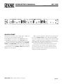
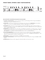
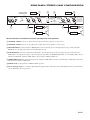
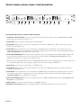
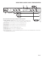
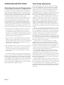
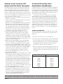
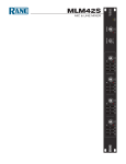
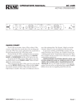
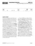
6 0 10 LEVEL 4 8 MASTER 2 CH 1 MASTER 2 6 0 10 LEVEL 4 8 MONO SUB LOW MUTE LOW 2 6 MIN MAX DELAY 4 8 LOW / HIGH LOW / MID 300 400 250 500 180 700 120 1.0k 90 1.5k 80 2.0k 75 3.0k 70 3.6k FREQUENCY 2 6 INACTIVE 0 10 LEVEL 4 HIGH 8 MONO STEREO 2 6 INACTIVE 0 10 LEVEL 4 8 CH 2 MASTER 2 6 0 10 LEVEL 4 LOW 8 MID MUTE 2 4 6 MIN MAX DELAY INACTIVE: MONO SUB 8 LOW / HIGH MID / HIGH 300 400 250 500 180 700 120 1.0k 90 1.5k 80 2.0k 75 3.0k 70 3.6k FREQUENCY 2 6 HIGH 0 10 LEVEL 4 HIGH 8 POWER ACTIVE CROSSOVER ACTIVE CROSSOVER AC 22S AC 22S IMPORTANT SAFETY INSTRUCTIONS 1. Read these instructions. 2. Keep these instructions. 3. Heed all warnings. 4. Follow all instructions. 5. Do not use this apparatus near water. 6. Clean only with a dry cloth. 7. Do not block any ventilation openings. Install in accordance with manufacturer’s instructions. 8. Do not install near any heat sources such as radiators, registers, stoves, or other apparatus (including amplifiers) that produce heat. 9. Do not defeat the safety purpose of the polarized or grounding-type plug. A polarized plug has two blades with one wider than the other. A grounding-type plug has two blades and a third grounding prong. The wide blade or third prong is provided for your safety. If the provided plug does not fit into your outlet, consult an electrician for replacement of the obsolete outlet. 10. Protect the power cord and plug from being walked on or pinched particularly at plugs, convenience receptacles, and the point where it exits from the apparatus. 11. Only use attachments and accessories specified by Rane. 12. Use only with the cart, stand, tripod, bracket, or table specified by the manufacturer, or sold with the apparatus. When a cart is used, use caution when moving the cart/apparatus combination to avoid injury from tip-over. 13. Unplug this apparatus during lightning storms or when unused for long periods of time. 14. Refer all servicing to qualified service personnel. Servicing is required when the apparatus has been damaged in any way, such as power supply cord or plug is damaged, liquid has been spilled or objects have fallen into the apparatus, the apparatus has been exposed to rain or moisture, does not operate normally, or has been dropped. 15. The plug on the power cord is the AC mains disconnect device and must remain readily operable. To completely disconnect this apparatus from the AC mains, disconnect the power supply cord plug from the AC receptacle. 16. This apparatus shall be connected to a mains socket outlet with a protective earthing connection. 17. When permanently connected, an all-pole mains switch with a contact separation of at least 3 mm in each pole shall be incorporated in the electrical installation of the building. 18. If rackmounting, provide adequate ventilation. Equipment may be located above or below this apparatus, but some equipment (like large power amplifiers) may cause an unacceptable amount of hum or may generate too much heat and degrade the performance of this apparatus. 19. This apparatus may be installed in an industry standard equipment rack. Use screws through all mounting holes to provide the best support. WARNING: To reduce the risk of fire or electric shock, do not expose this apparatus to rain or moisture. Apparatus shall not be exposed to dripping or splashing and no objects filled with liquids, such as vases, shall be placed on the apparatus. WARNING The symbols shown below are internationally accepted symbols that warn of potential hazards with electrical products. CAUTION RISK OF ELECTRIC SHOCK DO NOT OPEN ATTENTION: RISQUE DE CHOCS ELECTRIQUE - NE PAS OUVRIR To reduce the risk of electrical shock, do not open the unit. No user serviceable parts inside. Refer servicing to qualified service personnel. This symbol indicates that a dangerous voltage constituting a risk of electric shock is present within this unit. This symbol indicates that there are important operating and maintenance instructions in the literature accompanying this unit. WARNING: This product may contain chemicals known to the State of California to cause cancer, or birth defects or other reproductive harm. NOTE: This equipment has been tested and found to comply with the limits for a Class B digital device, pursuant to part 15 of the FCC Rules. These limits are designed to provide reasonable protection against harmful interference in a residential installation. This equipment generates, uses and can radiate radio frequency energy and, if not installed and used in accordance with the instructions, may cause harmful interference to radio communications. However, there is no guarantee that interference will not occur in a particular installation. If this equipment does cause harmful interference to radio or television reception, which can be determined by turning the equipment off and on, the user is encouraged to try to correct the interference by one or more of the following measures: • Reorient or relocate the receiving antenna. • Increase the separation between the equipment and receiver. • Connect the equipment into an outlet on a circuit different from that to which the receiver is connected. • Consult the dealer or an experienced radio/TV technician for help. CAUTION: Changes or modifications not expressly approved by Rane Corporation could void the user's authority to operate the equipment. This Class B digital apparatus complies with Canadian ICES-003. Cet appareil numérique de la classe B est conforme à la norme NMB-003 du Canada. INSTRUCTIONS DE SÉCURITÉ 1. Lisez ces instructions. 2. Gardez précieusement ces instructions. 3. Respectez les avertissements. 4. Suivez toutes les instructions. 5. Ne pas utiliser près d’une source d’eau. 6. Ne nettoyer qu’avec un chiffon doux. 7. N’obstruer aucune évacuation d’air. Effectuez l’installation en suivant les instructions du fabricant. 8. Ne pas disposer près d’une source de chaleur, c-à-d tout appareil produisant de la chaleur sans exception. 9. Ne pas modifier le cordon d’alimentation. Un cordon polarisé possède 2 lames, l’une plus large que l’autre. Un cordon avec tresse de masse possède 2 lames plus une 3è pour la terre. La lame large ou la tresse de masse assurent votre sécurité. Si le cordon fourni ne correspond pas à votre prise, contactez votre électricien. 10. Faites en sorte que le cordon ne soit pas piétiné, ni au niveau du fil, ni au niveau de ses broches, ni au niveau des connecteurs de vos appareils. 11. N’utilisez que des accessoires recommandés par Rane. 12. N’utilisez que les éléments de transport, stands, pieds ou tables spécifiés par le fabricant ou vendu avec l’appareil. Quand vous utlisez une valise de transport, prenez soin de vous déplacer avec cet équipement avec prudence afin d’éviter tout risque de blessure. 13. Débranchez cet appareil pendant un orage ou si vous ne l’utilisez pas pendant un certain temps. 14. Adressez-vous à du personnel qualifié pour tout service après vente. Celui-ci est nécessaire dans n’importe quel cas où l’appareil est abimé : si le cordon ou les fiches sont endommagés, si du liquide a été renversé ou si des objets sont tombés sur l’appareil, si celui-ci a été exposé à la pluie ou l’humidité, s’il ne fonctionne pas correctement ou est tombé. 15. La fiche du cordon d’alimentation sert à brancher le courant alternatif AC et doit absolument rester accessible. Pour déconnecter totalement l’appareil du secteur, débranchez le câble d’alimentation de la prise secteur. 16. Cet appareil doit être branché à une prise terre avec protection. 17. Quand il est branché de manière permanente, un disjoncteur tripolaire normalisé doit être incorporé dans l’installation électrique de l’immeuble. 18. En cas de montage en rack, laissez un espace suffisant pour la ventilation. Vous pouvez disposer d’autres appareils au-dessus ou en-dessous de celuici, mais certains (tels que de gros amplificateurs) peuvent provoquer un buzz ou générer trop de chaleur au risque d’endommager votre appareil et dégrader ses performances. 19. Cet appareil peut-être installé dans une baie standard ou un chassis normalisé pour un montage en rack. Visser chaque trou de chaque oreille de rack pour une meilleure fixation et sécurité. ATTENTION: afin d’éviter tout risque de feu ou de choc électrique, gardez cet appareil éloigné de toute source d’humidité et d’éclaboussures quelles qu’elles soient. L’appareil doit également être éloigné de tout objet possédant du liquide (boisson en bouteilles, vases,…). ATTENTION CAUTION RISK OF ELECTRIC SHOCK DO NOT OPEN ATTENTION: RISQUE DE CHOCS ELECTRIQUE - NE PAS OUVRIR Afin d’éviter tout risque de choc électrique, ne pas ouvrir l’appareil. Aucune pièce ne peut être changée par l’utilisateur. Contactez un SAV qualifié pour toute intervention. Les symboles ci-dessous sont reconnus internationalement comme prévenant tout risque électrique. Ce symbole indique que cette unité utilise un voltage élevé constituant un risque de choc électrique. Ce symbole indique la présence d’instructions d’utilisation et de maintenance importantes dans le document fourni. REMARQUE: Cet équipement a été testé et approuvé conforme aux limites pour un appareil numérique de classe B, conformément au chapitre 15 des règles de la FCC. Ces limites sont établis pour fournir une protection raisonnable contre tout risque d’interférences et peuvent provoquer une énergie de radiofréquence s'il n'est pas installé et utilisé conformément aux instructions, peut également provoquer des interférences aux niveaux des équipements de communication. Cependant, il n'existe aucune garantie que de telles interférences ne se produiront pas dans une installation particulière. Si cet équipement provoque des interférences en réception radio ou télévision, ceci peut être detecté en mettant l'équipement sous/hors tension, l'utilisateur est encouragé à essayer de corriger cette interférence par une ou plusieurs des mesures suivantes: • Réorienter ou déplacer l'antenne de réception. • Augmenter la distance entre l'équipement et le récepteur. • Connecter l'équipement à une sortie sur un circuit différent de celui sur lequel le récepteur est branché. • Consulter un revendeur ou un technicien radio / TV expérimenté. ATTENTION: Les changements ou modifications non expressément approuvés par Rane Corporation peuvent annuler l'autorité de l'utilisateur à manipuler cet équipement et rendre ainsi nulles toutes les conditions de garantie. Cet appareil numérique de classe B est conforme à la norme Canadienne ICES-003. Cet appareil numérique de classe B est conforme à la norme Canadienne NMB-003. OPERATORS MANUAL AC 22S ACTIVE CROSSOVER CH 1 MASTER 4 6 2 4 8 0 10 LEVEL LOW LOW / HIGH MUTE 300 400 250 500 180 700 120 1.0k 90 1.5k 80 2.0k 75 3.0k 70 3.6k FREQUENCY HIGH STEREO MONO SUB 6 2 4 8 0 10 LEVEL MASTER 6 2 LOW 8 MIN MAX DELAY LOW / MID 4 CH 2 MASTER 6 2 4 8 INACTIVE 6 2 0 10 LEVEL 4 8 0 10 LEVEL MONO LOW INACTIVE LOW / HIGH HIGH INACTIVE: MONO SUB 6 2 4 8 0 10 LEVEL 6 2 MUTE MID 8 MIN MAX DELAY 300 400 250 500 180 700 120 1.0k 90 1.5k 80 2.0k 75 3.0k 70 3.6k FREQUENCY MID / HIGH 4 AC 22S 6 2 ACTIVE CROSSOVER 8 0 10 LEVEL POWER HIGH QUICK START The AC 22S can be either a Stereo 2-Way or Mono 3-Way crossover. To keep operation simple, remember this: Labels above the controls refer to the 2-Way Stereo mode. Labels below the controls refer to the 3-Way Mono mode. The fact that the AC 22S is a multiple function unit means the outputs are switched around depending on the SYSTEM MODE and SUBWOOFER switches on the back of the unit. To operate the AC 22S in Stereo 2-Way mode, be sure that the Mode switch is set for STEREO 2-WAY. Follow the labels above the controls and jacks. WEAR PARTS: This product contains no wear parts. When operated in the Mono 3-Way mode, the switch should be set in the MONO 3-WAY position. Follow the labels below the controls and jacks. In Mono 3-Way mode the Channel 1 High Output is unusable. This output is the high-pass-only portion of the midrange filter. The Channel 1 High Level and the Channel 2 Master Level are also defeated on the front panel. In agreement with IEC and AES/ANSI standards, AC 22S wiring convention is pin 2 Positive, pin 3 Negative (return), pin 1 chassis ground. See the “Sound System Interconnection” RaneNote included with this manual for more information on cabling and grounding requirements. Manual-1 FRONT PANEL: STEREO 2-WAY CONFIGURATION 2-way operation: read the top row 1 2 3 4 CH 1 MASTER 4 4 8 0 10 LEVEL MASTER 6 LOW LOW / HIGH HIGH MUTE 300 400 250 500 180 700 120 1.0k 90 1.5k 80 2.0k 75 3.0k 70 3.6k FREQUENCY STEREO MONO SUB 6 2 5 6 2 4 8 0 10 LEVEL 6 2 LOW 8 MIN MAX DELAY LOW / MID 4 1 2 3 4 CH 2 MASTER INACTIVE: MONO SUB 6 2 4 8 INACTIVE 6 2 0 10 LEVEL 4 8 0 10 LEVEL MONO LOW INACTIVE 6 2 4 8 0 10 LEVEL 6 2 MUTE 8 MIN MAX DELAY 5 6 LOW / HIGH HIGH 300 400 250 500 180 700 120 1.0k 90 1.5k 80 2.0k 75 3.0k 70 3.6k FREQUENCY MID MID / HIGH 4 7 AC 22S 6 2 ACTIVE CROSSOVER 8 0 10 LEVEL POWER HIGH Observe the labels screened above the controls for stereo operation. 1 CHANNEL 1 MASTER LEVEL controls the overall Level of Channel 1 without altering the relative settings of the HIGH and LOW Outputs. Unity gain for all LEVEL controls is at “7”. 2 LOW LEVEL controls the Level of signal going to the LOW Output in this Channel. In the MONO SUB mode the Channel 1 LEVEL control sets the Level of the MONO SUB Output, Channel 2's LOW LEVEL control is inactive. 3 LOW MUTE: When pressed to the in position, all signal is removed from the LOW Output. This eases tune‑up procedures, as described on pages Manual-7 through 12. In the MONO SUB mode, the Channel 1 LOW MUTE switch mutes the MONO SUB Output, Channel 2's MUTE is inactive. 4 LOW DELAY control adds from 0 to 2 ms of time delay to the LOW OUT only. This allows a low frequency driver to be electronically phase‑aligned with a high frequency driver whose diaphragm is situated behind the low frequency diaphragm. Refer to Time Delay Adjustment on page Manual-6. NOTE: Both DELAY controls are inactive in the MONO SUB mode. 5 LOW / HIGH FREQUENCY: This 41‑detent selector determines the crossover frequency between the LOW and HIGH Outputs. The detents assure maximum accuracy and consistency between Channels. Refer to Selecting Crossover Frequencies on page Manual-6 to determine the proper setting for your particular system. 6 HIGH LEVEL controls the Level of signal going to the HIGH Output in this Channel. 7 CHANNEL 2 MASTER LEVEL controls the overall Level of Channel 2 without altering relative settings of the HIGH and LOW Outputs. 8 POWER indicator: If the power cable is plugged in and this yellow LED is lit, the unit ready to operate. Manual-2 REAR PANEL: STEREO 2-WAY CONFIGURATION 2-way operation: read the top row COMMERCIAL AUDIO 100-240 V EQUIPMENT 24TJ 50/60 Hz 7 WATTS AC 22S HIGH OUT Right Input LOW OUT 1 5 CH 2 IN STEREO 2-WAY MADE IN U.S.A. RANE CORP. MODE ACN 001 345 482 HIGH OUT MONO SUB: OMIT MID OUT 3 OMIT MONO Left Input HIGH OUT SUBWOOFER SWITCH MUST BE SET TO 2- CHANNEL FOR MONO 3-WAY R 7 6 CH 1 IN PIN 2: POSITIVE PIN 3: NEGATIVE PIN 1: CHASSIS GND SUBWOOFER MONO SUB 2-CHANNEL MONO 3-WAY High Amp 4 LOW OUT 2 OMIT MONO MONO SUB OUT LOW OUT 3 Low Amp MONO 3-WAY IN This device complies with Part 15 of the FCC Rules. Operation is subject to the following two conditions: (1) this device may not cause harmful interference, and (2) this device must accept any interference received, including interference that may cause undesired operation. High Amp 4 Low Amp Observe the labels screened above the Inputs and Outputs for stereo operation. 1 CHANNEL 1 INPUT connects to the left channel output of the mixer, equalizer or other source. 2 CHANNEL 2 INPUT connects to the right channel output of the mixer, equalizer or other source. 3 HIGH OUTPUTS: Connect Channel 1 HIGH OUT to the left channel input of the high frequency amp, and the Channel 2 HIGH OUT to the right channel input of the high frequency amp. 4 LOW OUTPUTS: Connect the Channel 1 LOW OUT to the left channel input of the low frequency amp and the Channel 2 LOW OUT to the right channel input of the low frequency amp. When the SUBWOOFER switch is set to MONO SUB, only use Channel 1 LOW OUT. Channel 2 LOW OUT is disconnected in MONO SUB mode. 5 SUBWOOFER switch disconnects the Output from Channel 2 LOW OUT and sums it with Channel 1 LOW OUT. The result is taken from the Channel 1 LOW OUT. 6 MODE switch: Set this switch for STEREO 2-WAY operation. 7 Universal Voltage Input: via a miniature IEC 60320 C6 appliance inlet. This mates with an IEC 60320 C5 line cord (USA domestic). Do not lift the ground connection! Manual-3 FRONT PANEL: MONO 3-WAY CONFIGURATION CH 1 MASTER 4 6 2 4 8 0 10 LEVEL MASTER 3-way operation: read the bottom row 1 LOW LOW / HIGH MUTE 300 400 250 500 180 700 120 1.0k 90 1.5k 80 2.0k 75 3.0k 70 3.6k FREQUENCY HIGH STEREO MONO SUB 6 2 4 8 0 10 LEVEL 6 2 8 MIN MAX DELAY 4 CH 2 MASTER 6 2 4 8 LOW LOW / MID INACTIVE 2 3 4 5 * 6 2 0 10 LEVEL LOW 4 8 6 2 0 10 LEVEL MONO LOW / HIGH HIGH INACTIVE: MONO SUB 4 8 0 10 LEVEL 6 2 MUTE 8 MIN MAX DELAY 300 400 250 500 180 700 120 1.0k 90 1.5k 80 2.0k 75 3.0k 70 3.6k FREQUENCY 4 AC 22S 6 2 ACTIVE CROSSOVER 8 0 10 LEVEL INACTIVE MID MID / HIGH HIGH * 6 7 8 9 0 POWER q Observe the labels below the controls for Mono operation. 1 CHANNEL 1 MASTER LEVEL controls the overall Level without altering the relative settings of the HIGH, MID and LOW Outputs. Unity gain for all Level controls is at “7”. 2 LOW LEVEL controls the Level of signal going to the LOW Output. 3 LOW MUTE: When pressed to the in position, all signal is removed from the LOW Output. This eases tune‑up procedure, as described on pages Manual 7-12. 4 LOW DELAY control adds from 0 to 2 ms of time Delay to the LOW Output only. This allows a low frequency driver to be electronically phase‑aligned with a high frequency driver whose diaphragm is situated behind the low frequency diaphragm. Refer to Time Delay Adjustment on page Manual-6 for the procedure. 5 LOW / MID FREQUENCY: This 41‑detent selector determines the crossover Frequency between LOW and MID Outputs. The detents will assure maximum accuracy and consistency between Channels. Refer to Selecting Crossover Frequencies on page Manual-6 to determine proper setting for your particular system. * NOTE: The Channel 1 HIGH LEVEL and Channel 2 MASTER LEVEL controls are automatically bypassed when the System Mode switch is set to MONO 3-WAY as shown on the facing page. Adjusting these controls have no effect in MONO mode. 6 MID LEVEL controls the Level of signal going to the MID Output. 7 MID MUTE: When pressed to the in position, all signal is removed from the MID Output. This eases tune‑up procedures, as described in pages Manual 7-12. 8 MID DELAY control adds from 0 to 2 ms of time Delay to the MID Output only. This allows a mid frequency driver to be electronically phase‑aligned with a high frequency driver whose diaphragm is situated behind the mid frequency diaphragm. Refer to Time Delay Alignment on page Manual-6 for procedure. 9 MID / HIGH FREQUENCY: sets the crossover Frequency between the MID and HIGH Outputs. Refer to Selecting Crossover Frequencies on page Manual-6. 0 HIGH LEVEL controls the Level of signal going to the HIGH Output only. q POWER switch and indicator: If the power cable is plugged in and this yellow LED is lit, the unit ready to operate. Manual-4 REAR PANEL: MONO 3-WAY CONFIGURATION 5 COMMERCIAL AUDIO 100-240 V EQUIPMENT 24TJ 50/60 Hz 7 WATTS AC 22S HIGH OUT LOW OUT CH 2 IN MODE HIGH OUT 2-way operation: read the bottom row HIGH OUT SUBWOOFER SWITCH MUST BE SET TO 2- CHANNEL FOR MONO 3-WAY ACN 001 345 482 MONO SUB: OMIT MID OUT 3 OMIT MONO Input STEREO 2-WAY MADE IN U.S.A. RANE CORP. R 7 6 LOW OUT 1 CH 1 IN PIN 2: POSITIVE PIN 3: NEGATIVE PIN 1: CHASSIS GND SUBWOOFER MONO SUB 2-CHANNEL MONO 3-WAY OMIT MONO MONO SUB OUT LOW OUT MONO 3-WAY IN This device complies with Part 15 of the FCC Rules. Operation is subject to the following two conditions: (1) this device may not cause harmful interference, and (2) this device must accept any interference received, including interference that may cause undesired operation. High Amp 4 Mid Amp Observe the labels below the Inputs and Outputs for Mono operation. 1 MONO (CHANNEL 1) INPUT: Plug the output of the mixer, equalizer or other signal source to this Input for mono operation. Do not use the Channel 2 INPUT for MONO 3-WAY operation. 4 Low Amp 2 HIGH OUTPUT: Connect this Output to the input of the high frequency amp. 3 MID OUTPUT: Connect this Output to the input of the mid frequency amp. 4 LOW OUTPUT: Connect this Output to the input of the low frequency amp. 5 MODE switch: Set this switch for MONO 3-WAY operation. 6 SUBWOOFER switch: Set this switch for 2-CHANNEL operation. 7 Universal Voltage Input: via a miniature IEC 60320 C6 appliance inlet. This mates with an IEC 60320 C5 line cord (USA domestic). Do not lift the ground connection! Manual-5 OPERATING INSTRUCTIONS Selecting Crossover Frequencies Most speaker manufacturers supply low and/or high frequency cut‑off points for each driver, especially if these are supplied in a system. These cut‑off frequencies are based on each driver’s performance at and beyond this point, with a certain safety margin to accommodate more gentle filter roll‑offs and resultant higher output beyond the recommended performance range. The AC 22S utilizes 41‑detent crossover Frequency selectors which are precision potentiometers. The detents assure consistent accuracy from channel to channel and unit to unit. This is a distinct advantage over the continuously variable designs using low‑tolerance parts, possible knob misalignment and panel screening variations. Even with 41 choices it is possible that the exact recommended Crossover Frequency may not fall on one of the detents on the selector. Not to panic, for these sound reasons: 1. The AC 22S possesses 24 dB/octave roll‑off, so the Crossover points may be set to the nearest detent above or below the recommended limit with virtually no hazard to the driver or degradation in sound quality. If extremely high power levels are expected, it is safer to defer to the high frequency drivers and shift the Frequency up rather than down. 2. Detents do not rely on knob alignment, silk-screen accuracy, parallax and other variables which erode the accuracy of continuously variable designs. Chances are that even careful visual alignment on these will often yield a frequency error greater than a full detent on the AC 22S. 3. If it is absolutely critical to obtain the exact crossover frequency (Mil Spec., P.A., etc.), the selector can be positioned between detents if necessary. This of course will require the aid of a precision signal generator and other equipment to verify the exact setting. For best overall system results, try to choose the speaker components so that each operates well within its recommended limits. This will provide valuable leeway so that you may move crossover points in order to fine‑tune the system, and will also yield higher system reliability. If at all possible, beg, borrow or best yet always use some kind of realtime analyzer to tune your crossover and fine‑tune the system for each different location with an equalizer. Keep reading for further alignment details. Manual-6 Time Delay Adjustment Before jumping feet first into the realm of time delay and how to adjust it, it might help to spend a moment here to re‑affirm why on earth this Delay is really necessary. For a detailed and enjoyable short course on time delay, Linkwitz‑Riley and other mouth‑watering details, we urge you to read the RaneNote “Linkwitz-Riley Crossovers” available in the Library section of the Rane website. In the way of summary, a few words are in order here to outline the basic effects of time delay in crossovers. Problems pop up when two different speakers emit the same frequency as occurs in the crossover regions of two, three, four and five way systems. Because the two drivers are displaced vertically, cancellation occurs somewhere off‑axis because the sound waves have to travel different distances from the two speakers and hence, will arrive shifted in phase. This forms a “lobe” or radiation pattern, bounded on either side by cancellation lines or axes, which narrow the dispersion pattern or listening area of the speaker. Fine. So we put up with it. But to make matters worse, when the two drivers are horizontally displaced – that is, one is in the front of or behind the other, this “lobe” or dispersion pattern gets tilted (usually upward) toward the driver that is further behind (see Figure 1). This gets hard to put up with, because the end result is that your speaker system will have two, three, four or more tilted radiation patterns and only two or three people in the house will have decent seats. And we’re not talking trivial pursuits here—this rampant lobing error can make a sound system a real headache, to listener and operator alike. The idea, then, is to be sure that all drivers are vertically aligned and that all components are always in phase. Then all the main lobes are on‑axis, well behaved, and the system enjoys the widest possible dispersion pattern so that everyone gets good sound. The one catch is that in many cases it is physically or otherwise impossible to get all the drivers vertically lined up at the sound source. This is where time delay comes in. By electronically delaying the signal going to the driver up front, enough time is allowed for the sound from the rear driver to literally catch up to the forward driver’s voice coil, so that signal from both drivers is emitted in phase (See Figure 2). And it works! Time delay can make an appreciable improvement in overall sound. The trick is finding the proper amount of time delay: hence the rest of this section. Unfortunately the amount of time delay is a function of two factors (life ceased to be simple after age 9, right?): the amount of horizontal displacement between driver voice coils, and the actual crossover frequency involved. Setting Delay controls by ear is supposedly possible, but very tricky and unreliable. The following methods are a couple of (but by no means all) means of setting time Delay. Time Delay Adjustment Using a Realtime Analyzer & Pink Noise. This method outlines the use of a realtime analyzer, pink noise generator and flat response microphone to set crossover time Delay. The procedure applies to virtually any analyzer system. We recommend using a one‑third or two‑thirds octave analyzer as either of these is more likely to match your specific crossover points than a one‑octave analyzer. And it is important to match the analyzer to the crossover point as closely as possible for proper phase alignment, otherwise the analyzer readings may be misleading. STEP BY STEP PROCEDURE A 3-Way mode consisting of High, Mid and Low drivers is used here as an example. For 2-Way systems, use the same procedure by replacing LOW for MID and following steps 2 through 5. NOTE: If you are running two separate Channels on the crossover, tune up only one Channel at a time, using the same procedure for both. 1. Place the analyzer microphone about 15 feet in front of the speaker stack and at a height about midway between the high and mid drivers. Turn all crossover LEVEL controls fully down. 2. Connect the pink noise source to the INPUT of the crossover (or mixer or wherever is convenient). Turn up the crossover MASTER LEVEL control and the MID LEVEL control until noise is heard from only the mid driver at a comfortable volume. 3. With a healthy but not uncomfortable volume of noise from the mid driver, set the analyzer display level control so the readout corresponding to the high crossover frequency is reading 0 dB. 4. Now press in the MID MUTE switch on the crossover so that the tone is removed from the mid driver. Without re‑adjusting either the meter or the crossover MASTER or MID LEVEL controls, turn up the HIGH LEVEL control until the tone coming from only the high driver reads 0 dB. 5. Now release the MID MUTE switch on the crossover so pink noise is heard from both the high and mid drivers. Switch the display sensitivity to ±3 dB on the analyzer (not necessary with full scale analyzers) and observe the display reading at the crossover frequency: i. If the display shows a +3 dB reading, then the drivers are properly phase aligned and no delay is necessary; leave the MID DELAY control at minimum. Fig. 1 In-Phase Axis Response Without Time Delay Fig. 2 Corrected In-Phase Axis Response With Electronic Time Delay on Low Frequency Driver ii. If the display shows less than +3 dB reading, slowing turn up the MID DELAY control on the crossover until the display shows +3 dB. Now the drivers are electronically phase aligned and the MID DELAY control should be left in this position at all times unless the speaker system is physically altered. iii. If you have turned the MID DELAY control all the way up and still do not have a +3 dB reading, you will have to physically move the high driver farther forward until the display shows +3 dB. The amount of displacement correction available from the delay depends on the actual crossover frequency: the higher the frequency, the less amount of correction capability. If the drivers are built into a single cabinet and/or it is impossible to change relative positions, then you will have to obtain additional external delay to achieve proper phase alignment. Manual-7 iv. If turning the MID DELAY control up makes the display reading decrease instead of increase, this means that the high driver is actually in front of the mid driver; adding delay to the mid driver then only worsens the situation. There are a couple of ways to deal with this: a. Try to move the high driver back as far as possible without losing stability in balancing the speaker stack. You may want to raise it up as well to restore dispersion close to the stack. If you cannot move the high driver, then you will have to obtain an additional delay source to align the high and mid drivers, such as the Rane AD 22B. The built‑in Delay system in the AC 22S is designed to accommodate the majority of common speaker configurations; if you encounter confusion or difficulty with your particular system, it is best to consult your dealer or the Rane factory for assistance. b. If this decrease in the display due to the DELAY control occurs at a low frequency crossover point below about 150 Hz, set the DELAY control to minimum and leave it there. Frequencies below 150 Hz are actually omnidirectional, so that phase misalignment is virtually inaudible below this point. Subwoofers will often possess long folded or straight horns, resulting in the diaphragm being well behind the rest of the stack. Most authorities agree that phase alignment of subwoofers is unnecessary. Otherwise you will have to obtain additional delay equipment to align these to the rest of the system. 6. Lower the microphone until it is vertically midway between the mid and low drivers. Repeat steps 2 through 5, using the crossover LEVEL control, MUTE switch and next DELAY control. You may start each series of steps 2 through 5 at a different volume as necessary — but once the Levels are set in step 3 do not alter these until step 5 is completed. Once all of the crossover DELAY controls are set, adjust the output LEVEL controls as outlined in the Setting Levels Section on page Manual-12. Time Delay Adjustment Using an SPL Meter & Tone Generator Now that good quality realtime analyzers are becoming more affordable and easier to use, there are few reasons why one of these should not be regularly used in any sound system. If an analyzer is simply not available or for some reason inappropriate, an accurate Delay setting can be obtained by using a straightforward SPL meter (obtainable at most local electronics stores) and some kind of variable tone generator. In order to exclude the effect of room acoustics and imperfect driver response, only the crossover frequencies are to be emitted (one at a time) by the tone generator. First, the highest crossover frequency is run through the crossover and each of the two speakers sharing the crossover point is set separately to an arbitrary 0 dB level on the SPL meter. When both drivers emit the crossover tone simultaneously, the combined response should read +3 dB higher on the meter. If the drivers are not phase aligned, some cancellation will occur on‑axis, resulting in a combined response less than +3 dB. Turning the DELAY control up causes the lower frequency driver to electronically move backward until the SPL meter reads +3 dB; then the two drivers are electronically aligned and the on‑axis cancellation is eliminated (see Figure 2 on page 6). This procedure is then repeated for the next lower crossover point(s). STEP BY STEP PROCEDURE A 3-Way mode consisting of high, mid and low drivers is used here as an example. For other configurations, use the same procedure starting with the highest crossover point and repeat steps 2 through 5 for each lower crossover point. 1. Set the tone generator to the highest crossover frequency and plug it into the Input of the crossover. Turn all crossover LEVEL controls fully down. 2. Position the SPL meter (microphone) about 15 feet in front of the speakers and at a height about midway between the high and mid drivers. It is very important that the meter remain in exactly the same position throughout the test, so affix it to a mic stand, small tree or other stable object. Set the switches on the SPL meter to C-weighting, slow. Be sure to minimize background noise (air conditioners, fans, traffic, wild animals, etc.) as these will effect the meter reading. 3. Slowly turn up both the crossover MASTER and MID LEVEL controls until the tone is heard through the mid driver. Adjust the SPL meter control and/or the crossover LEVEL controls until you obtain a 0 dB reading on the meter. Verify that no sound is coming from any other speakers except the mid driver. 4. Now press in the MID MUTE switch on the crossover so that the tone is removed from the mid driver. Without re‑adjusting either the meter or the crossover MASTER or MID LEVEL controls, turn up the HIGH LEVEL control until the tone coming from only the high driver reads 0 dB on the SPL meter. Manual-8 5. Now release the MID MUTE switch so that the tone is emitted from both the high and mid drivers. Check the reading on the SPL meter: i. If the meter reads +3 dB, then the drivers are properly phase aligned and no Delay is necessary; leave the MID DELAY control at full minimum. ii. If the meter reads less than +3 dB, slowly turn up the MID DELAY control until the meter just reads +3 dB. Now the drivers are electronically phase aligned and the DELAY control should be left in this position at all times, unless the speaker system is physically altered. 6. Tune the tone generator to the next lower crossover frequency and then repeat steps 2 through 5, using the appropriate Level and Delay controls. Once the Delay control is set, you may re‑adjust any of the crossover Level controls at the beginning of each alignment procedure. Once all of the crossover Delay controls are set, then re‑adjust the output Level controls as outlined in Setting the Output Level Controls on page Manual-11. iii. If you have turned the MID DELAY control all the way up and still do not obtain a +3 dB reading, you will have to physically move the high driver farther forward until the SPL meter reads +3 dB. The amount of displacement corrections available from the Delay depends on the actual crossover frequency: the higher the frequency the less amount of correction capability. If the drivers are built into a single cabinet and/or it is impossible to change relative positions, then you will have to obtain additional delay to achieve proper phase alignment such as the Rane AD 22B. iv. If turning the MID DELAY control up makes the SPL reading decrease instead of increase, this means that the high driver is actually in front of the mid driver; adding delay to the mid driver then only worsens the situation. There are a couple of ways to deal with this: a. Try to move the high driver back as far as possible without losing stability in balancing the speaker stack. You may want to raise it up as well to restore dispersion close to the stack. If you cannot move the high driver, then you will have to obtain an additional external delay source to align the high and mid drivers. The built‑in Delay system in the AC 22S is designed to accommodate the majority of common speaker configurations; if you encounter confusion or difficulty with your particular system, it is best to consult your dealer or the Rane factory for assistance. b. If this decrease in the display due to the LOW DELAY control occurs at a low frequency crossover point below about 150 Hz, set the LOW DELAY control to minimum and leave it there. Frequencies below 150 Hz are actually omnidirectional, so that phase misalignment is virtually inaudible below this point. Subwoofers will often possess long folded or straight horns, resulting in the diaphragm being well behind the rest of the stack. Most authorities agree that phase alignment of subwoofers is unnecessary. Otherwise you will have to obtain additional delay equipment to align these to the rest of the system. Manual-9 Delay vs. Frequency Table If you do not have the equipment necessary to electronically align the system as described in the previous sections, you may use the table below to obtain a rough and approximate phase alignment of your drivers. Measure the horizontal displacement between the voice coils of the two adjacent drivers sharing the same crossover point, then find the column in the table nearest your actual displacement. Move down this column to the proper Crossover Frequency as indicated on the left of the table: the corresponding DELAY knob setting will then be the closest for your system. For example, if you have a two‑way system crossed over at 800 Hz with the compression driver voice coil located about 9" behind the woofer voice coil, the Delay knob setting corresponding to a 9" displacement at 800 Hz on the table would be “5” as indicated on the front panel. In order to phase‑align two drivers you must observe only the crossover frequency, which is common to both drivers. Pink noise can be used if all other frequencies are disregarded, since room acoustics and imperfect driver response will cause erroneous alignment attempts. Using pink noise as a source, each driver is individually tuned to an arbitrary 0 dB level on the analyzer display only at the crossover frequency. When both are turned on simultaneously, the combined response of the two drivers should read +3 dB higher at the crossover frequency on the display. If the drivers are not phase‑aligned, some cancellation will occur on‑axis, resulting in a combined response less than +3 dB. Turning up the DELAY control causes the lower driver to electronically move backward until the analyzer reads +3 dB; then the two drivers are electronically aligned and the on‑axis cancellation is eliminated (see Figure 2 on page Manual-6). Voice Coil Displacement (Inches) (Hz) .75"1.5"3" 6" 9" 12"15"18"21"24" 70 11.5 22.5 3.5 5678MAX 80 11.5 22.5 3.5 5678MAX 100 11.5 22.5 3.5 5678MAX 150 11.5 22.5 3.5 567MAX Crossover Frequency 200 11.5 22.5 3.5 567MAX 250 11.5 22.5 3.5 578MAX 300 1 1.52 2.53.55.57 MAX 400 11.5 22.5 468MAX 450 11.5 22.5 468MAX 500 11.5 22.5 468MAX 800 11.5 2357MAX lk 11.5 2.2 36MAX 1.2k 1 1.52.23.5MAX 1.5k 1 1.52.33.5MAX 2k 1 1.52.3MAX 2.5k 1 1.52.3MAX 3k 1 1.72.4MAX 3.6k 1 1.7MAX 4k 1 1.8 Displacement MAX 6k 12MAX 7k 1.2 MAX Fig. 3. Vertical Driver Displacement Manual-10 Setting the Output Level Controls Choosing the crossover frequencies was the easy part. Now it gets real fun. The idea is to set the output LEVEL controls on the crossover so that the entire speaker system has a uniform, flat response. Unfortunately, the room in which the speakers are placed has a habit of always getting into the act, so things get messy. As a result there seems to be two schools of thought regarding the use of active crossovers. The Set‑lt‑Once‑And-Glue‑lt School. The philosophy here is to use the crossover to flatten system response as much as possible without room acoustics involved. This means setting up the system outside (unless you happen to have a very large anechoic chamber handy) and with the aid of a realtime analyzer and pink noise source, adjust all of the crossover outputs so the system is as flat as possible. Once the system is tuned, the crossover is then locked behind a security cover (posted guard is optional) and never again touched. It is then the job of the system equalizer(s) to normalize or flatten the system to each different room. The Fix‑lt‑With-The‑Crossover School. Here the crossover knobs get a good workout, for the crossover is used at each location to help flatten the system along with the equalizer. Some even maintain that a good active crossover can work alone like a parametric equalizer in the hands of an expert. This does require experience, skill, and the right equipment to back it up (not to mention a licensed set of ears). Regardless of which school you profess, the absolute importance and effectiveness of some kind of realtime analyzer in your system cannot be overstressed! No, this is not a callous plug for our other products; analyzers in general have come a long way. They’re out of the lab (i.e. closet) and into the hands of every smart working musician and sound technician. An analyzer will save tremendous amounts of time and provide the absolute consistency, accuracy, and plain old good sound that very few ears on this earth can deliver. They are affordable, easy to use and amazingly effective. You owe it to yourself and your audience to at least look into one of these analyzers — you’ll wonder how you managed at all without one. Whether by analyzer or by ear, here are a few recommended methods of setting the crossover Output Levels. Setting Levels With a Realtime Analyzer NOTE: If you are running two Channels, tune up only one Channel at a time. 1. Set all LEVEL controls to minimum; leave Delay and crossover Frequency controls as set previously. 2. Place the analyzer microphone at least 15 feet away from the speaker stack, on axis (dead ahead) and about chest level. Minimize any background noise (fans, air conditioners, traffic, etc.) that could affect the readings. 3. Run pink noise through the system, either through a mixer channel or directly into the crossover. Turn all amplifier controls at least half way up. 4. We will use the 3‑Way mode here as an example—the procedure applies to all configurations. Turn up the MASTER LEVEL control about half way. 5. Slowly turn up the LOW LEVEL control until you hear a healthy level of noise through the low frequency drivers (it should sound like rumble). 6. Adjust the analyzer display control so it shows the greatest number of 0 dB indicators below the crossover frequency. 7. Now slowly turn up the MID LEVEL control until the display shows the same output level average as the low frequency section. 8. Repeat this procedure for all crossover frequency sections, so the end result is an analyzer display that is flat as possible. IMPORTANT: Compression driver or horn roll‑off, bass roll‑off, and room acoustic usually cannot be corrected by the crossover. If you are using constant directivity horns, see the Constant Directivity Horn Modification section on page 12. If, for example, you are adjusting the HIGH FREQUENCY control and observe a decline in frequency response somewhat above the crossover point, then set the HIGH LEVEL control for equal display level near the crossover point and leave it there. Then use an equalizer or bank of tweeters to correct the roll‑off problem. If you are tuning the system in a room, the acoustics will greatly influence the system response, as shown by the analyzer. Check the system response on an analyzer at several other locations and adjust the crossover as necessary to reach a fixed compromise setting if desired. If you plan to use the analyzer only once to set the crossover, set up the speaker system in a quiet place outside or in a very large concert theater, and run pink noise at low levels with closer microphone placement to keep the room acoustics out of the picture as much as possible. Manual-11 Setting Levels Using an SPL Meter and Pink Noise Generator Constant Directivity Horn Equalization Modification The MUTE switches on the AC 22S make using an SPL meter an easy and relatively accurate means of tuning a system. First, obtain a good SPL meter from a local electronics or hi-fi store. Second, and perhaps a little trickier, get a hold of a pink noise generator—again try electronics and hi‑fi stores. You may also use a sweep or tone generator in place of a pink noise source. If so, be sure to look at several different tones within each crossover section to get a good average of driver response. 1. Run pink noise into the crossover Inputs (through the mixer or directly, as is convenient). 2. To start, turn all crossover LEVEL(s) all the way down and all amplifier level controls at least half way up. 3. Turn the crossover MASTER LEVEL(s) half way up. Place the SPL meter at least 15 feet from the speaker stack and about chest high. Once positioned, the SPL meter must remain in the exact same location for the rest of the procedure. Minimize all background noise (fans, air conditioners, traffic, wild animals, etc.) to get accurate readings. Set the SPL meter to “C-weighting”, “slow” if those switches are present. 4. Slowly turn the LOW LEVEL up until there is a healthy rumble coming from the bass speakers (For this example the 3‑Way mode is used—the same procedure applies to all configurations, starting with the lowest frequency and ending with the highest). Adjust the SPL meter and/or LOW LEVEL until you get a 0dB reading on the meter. After this point do not change the controls on the SPL meter. 5. While leaving the LOW LEVEL control at the 0 dB adjustment just obtained, press the LOW MUTE switch on the crossover so the pink noise disappears from the bass speakers. 6. Now slowly turn up the MID LEVEL control so pink noise is heard from the mid frequency speakers. Without changing any settings on the SPL meter, adjust the crossover MID LEVEL control until you obtain a 0 dB reading on the SPL meter. Now the low and mid speakers are set at the same level. 7. Now press the MID MUTE switch on the crossover so the pink noise again disappears. 8. Repeat this process for each crossover frequency section, ending with the highest frequency. NOTE: It is possible you may turn one of the frequency section output LEVEL controls all the way up and still not have enough volume for a 0 dB reading (as determined by previous section levels). This is probably due to different sensitivities of amps, speakers and other level controls in the system. When this happens, re‑set the SPL meter so that it reads 0 dB on this frequency section (you may have to “down range” the meter and re‑adjust the crossover MASTER LEVEL control). Now go back and re‑adjust the previous crossover LEVEL controls, turning these down to get a 0 dB reading on the meter. 9. Once the HIGH LEVEL control is set for 0 dB on the meter, disengage all of the MUTE switches on the crossover, and check that noise is emitting from all the speaker components. The crossover should now be aligned. Make any overall level adjustments with the MASTER LEVEL level controls and leave the output LEVEL controls unchanged. Constant Directivity (or CD) horns need additional equalization to help cover the same area a long throw horn can cover. Additional circuitry has been added to the AC 22S layout for the additional equalization of the High Frequency outputs for CD horns. This modification should only be attempted by an experienced technician who is adept at soldering. It is important to know the 3 dB down point of the CD driver's frequency response. The manufacturer of your driver should be able to supply you with a chart showing a frequency response curve. Find the point where the high end starts to roll off, and look for the point on the chart that is 3 dB down from that point (toward the right, as the higher frequencies roll off). Find the frequency at the bottom of the chart of this point — an approximate is fine, you don't have to be exact. Find the closest frequency in the table below to determine the correct value capacitor to install in the AC 22S to correct for this high frequency roll off. STEP BY STEP PROCEDURE The following procedure is for Stereo 2-Way. For a Mono 3-Way system with a CD horn on the high output, only place C54 in Channel 2. 1. Remove the top and bottom covers of the AC 22S. 2. Locate the positions for C53 and C54 on the board description page of the schematics and on the circuit board. These are near the front by the Frequency controls, and marked with HORN EQ OPTION. C53 is the capacitor location for Channel 1, and C54 is the capacitor location for Channel 2. 3. Clean the solder pad on the underside of the board so that the appropriate capacitor can be inserted. Install the capacitor, and solder the leads from the underside using fresh solder. Clip the excess leads. 3 dB Down Frequency Capacitor 2.0 kHz .0068 µf 2.5 kHz .0056 µf 3.0 kHz .0047 µf 3.7 kHz .0039 µf 4.0 kHz .0036 µf 5.0 kHz .0030 µf 6.0 kHz .0024 µf ©Rane Corporation 10802 47th Ave. W., Mukilteo WA 98275-5000 USA TEL 425-355-6000 FAX 425-347-7757 WEB rane.com Manual-12 111024