1
Operator's Manual
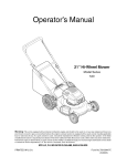
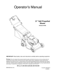
21" Mulching
Push Mower
Model 247.385010
Factory No. 11A-596C402
IMPORTANT:
Read safety rules and instructions
carefully
before operating
equipment.
Warning:
This unit is equipped with an internal combustion engine and should not be used on or near any unimproved forestcovered, brush-covered or grass-covered land unless the engine's exhaust system is equipped with a spark arrester meeting
applicable local or state laws (if any). If a spark arrester is used, it should be maintained in effective working order by the operator.
In the State of California the above =srequired by law (Section 4442 of the California Public Resources Code). Other states may have
similar laws. Federal laws apply on federal lands. A spark arrester for the muffler is available through your nearest engine authorized
service dealer or contact the service department, P.O. Box 361131 Cleveland, Ohio 44136-0019.
MTD LLC, P.O.BOX361131CLEVELAND,OHIO44136-0019
PRINTED IN U.S.A.
FORM NO. 769-00064
(2/02)
TABLE OF CONTENTS
Content
Page
Important Safe Operation Practices ........................................................................
3
Slope Gauge ...........................................................................................................
6
Assembling Your Lawn Mower ................................................................................
7
Know Your Lawn Mower ..........................................................................................
9
Operating Your Lawn Mower ...................................................................................
10
Maintaining Your Lawn Mower ................................................................................
12
Making Adjustments ................................................................................................
14
Off-Season Storage .................................................................................................
15
Troubleshooting
16
......................................................................................................
Parts List .................................................................................................................
17
FINDINGMODELNUMBER
This Operator's Manual is an important part of your new lawn mower. It will help you assemble, prepare and
maintain the unit for best performance. Please read and understand what it says.
Before you start assembling your new equipment, please locate the model plate on the equipment
and copy the information from it in the space provided below. This information is very important if you
need help from our Customer Support Department or an authorized dealer.
You can locate the model number by looking at the rear portion of the deck's surface. A sample model plate is
explained below. For future reference, please copy the model number and the serial number of the equipment
in the space below.
Copy the model number here:
www.yardman.com
• MTD
LLC
O. BOX 361131
CLEVELAND,OH
44136
330-220-4683
800-800-731121
Copy the serial number here:
ENGINEINFORMATION
The engine manufacturer is responsible for all engine-related issues with regards to performance, power-rating,
specifications, warranty and service. Please refer to the engine manufacturer's Owner's/Operator's Manual packed
separately with your unit for more information.
CALLINGCUSTOMER
SUPPORT
If you have difficulty assembling this product or have any questions regarding the controls, operation or
maintenance of this unit, please call the Customer Support Department.
Call 1- (330) 220-4MTD (4683) or 1- (800) 800-7310 to reach a Customer Support representative.
Please have your unit's model number and serial number ready when you call. See previous section
to locate this information. You will be asked to enter the serial number in order to process your call.
SECTION1: IMPORTANT
SAFEOPERATION
PRACTICES
This symbol points out important safety instructions which, if not followed, could endanger the personal
safety and/or property of yourself and others. Read and follow all instructions in this manual before
attempting to operate your lawn mower. Failure to comply with these instructions may result in personal
injury. When you see this symbol, heed its warning.
DANGER: Your lawn mower was built to be operated according to the rules for safe operation in this manual. As
with any type of power equipment, carelessness or error on the part of the operator can result in serious injury. This
lawn mower is capable of amputating hands and feet and throwing objects. Failure to observe the following safety
instructions could result in serious injury or death.
_
California
cause
cancer,
birth defects
or other
reproductive
ARNING: to The
Engine
Exhaust
from this
product
contains harm.
chemicals
known to the State of
GENERAL
OPERATION
Read this operator's manual carefully in its entirety
before attempting to assemble this machine.
Read, understand, and follow all instructions on
the machine and in the manual(s) before
operation. Be completely familiar with the controls
and the proper use of this machine before
operating it. Keep this manual in a safe place for
future and regular reference and for ordering
replacement parts.
Your rotary mower is a precision piece of power
equipment, not a plaything. Therefore, exercise
extreme caution at all times. Your unit has been
designed to perform one job: to mow grass. Do not
use it for any other purpose.
Never allow children under 14 years old to operate
a power mower. Children 14 years old and over
should only operate mower under close parental
supervision. Only responsible individuals who are
familiar with these rules of safe operation should
be allowed to use your mower.
Keep the area of operation clear of all persons,
particularly small children and pets. Stop engine
when they are in the vicinity of your mower to help
prevent blade contact or thrown object injury.
Although the area of operation should be
completely cleared of foreign objects, an object
may have been overlooked and could be
accidentally thrown by the mower in any direction
and cause serious personal injury to the operator
or any others allowed in the area.
Wear sturdy, rough-soled work shoes and closefitting slacks and shirts. Shirts and pants that cover
the arms and legs and steel-toed shoes are
recommended. Do not wear loose fitting clothes or
jewelry. They can be caught in moving parts.
Never operate a unit in bare feet, sandals, slippery
or light weight (e.g. canvas) shoes.
•
•
•
•
•
•
•
Always wear safety glasses or safety goggles
during operation or while performing an
adjustment or repair, to protect eyes from foreign
objects that may be thrown from the machine in
any direction.
Thoroughly inspect the area where the equipment
is to be used. Remove all stones, sticks, wire,
bones, toys and other foreign objects which could
be picked up and thrown by the mower in any
direction and cause serious personal injury to the
operator or any others allowed in the area. Plan
your mowing pattern to avoid discharge of material
toward roads, sidewalks, bystanders and the like.
To help avoid a thrown objects injury, keep
children, bystanders and helpers at least 75 feet
from the mower while it is in operation.
Do not put hands or feet near or under rotating
parts. Keep clear of discharge opening at all times
as the rotating blade can cause injury.
Many injuries occur as a result of the mower being
pulled over the foot during a fall. Do not hang on to
the mower if you are falling; release the handle
immediately.
Never pull the mower toward you while you are
walking. If you must back the mower away from a
wall or obstruction first look down and behind, and
then follow these steps:
a. Step back from the mower to fully extend your
arms.
b. Be sure you are well balanced with sure
footing.
c. Pull the mower back slowly, no more than half
way toward you.
d. Repeat these steps as needed.
Do not operate the mower while under the
influence of alcohol or drugs.
Do not engage the self-propelled mechanism on
units so equipped while starting engine.
Thebladecontrolhandleisa safetydevice.Never •
Always be sure of your footing. A slip and fall can
attempttobypassitsoperation.
Doingsomakes
cause serious personal injury. If you feel you are
thesafetydeviceinoperative
andmayresultin
losing your balance release the blade control
personal
injurythroughcontactwiththerotating
handle immediately and the blade will stop in less
than 3 seconds.
blade.Thebladecontrolhandlemustoperate
Do not:
easilyinbothdirections
andautomatically
returnto
thedisengaged
positionwhenreleased.
•
Do not mow near drop-offs, ditches or
Neveroperatethemowerinwetgrass.Alwaysbe
embankments. The operator could lose footing or
sureofyourfootingtoavoidseriousinjury.
balance.
Keepafirmholdonthehandleandwalk,never
•
Do not mow slopes greater than 15 degrees as
run.Ifyoufeelyouarelosingyourfooting,
shown on the slope gauge.
RELEASE
THEBLADECONTROL
HANDLE
•
Do not mow on wet grass. Reduced footing could
IMMEDIATELY
andthebladewillstoprotating
cause slipping.
withinthreeseconds.
Mowonlyindaylightorgoodartificiallight.Stop
Children
bladewhencrossinggraveldrives,walksor roads.
Tragic accidents can occur if the operator is not
Iftheequipment
shouldstarttovibrateabnormally,
alert to the presence of children. Children are often
stoptheengineandcheckimmediately
forthe
attracted to the mower and the mowing activity.
cause.Vibration
is generally
a warning
oftrouble.
Never assume that children will remain where you
Shuttheengineoffandwaituntilthebladecomes
last saw them.
toa complete
stopbeforeremoving
thegrass
Keep children out of the mowing area and under
catcherorunclogging
thechute.Thecuttingblade
the
watchful care of a responsible adult other than
continues
torotateforafewseconds
afterthe
the
operator.
engineisshutoff.Neverplaceanypartofthebody
Be alert and turn mower off if a child enters the
inthebladeareauntilyouaresurethebladehas
area.
stoppedrotating.
Before and while moving backwards, look behind
Neveroperatemowerwithoutproperguards,
and
down for small children or other objects.
grasscatcher,platesorothersafetyprotective
Never
allow children under age 14 to operate the
devicesinplace.
mower. Children 14 years of age and above
Mufflerandenginebecomehotandcancausea
should read and understand the operation
burn.Donottouch.
instructions and safety rules in this manual.
Onlyuseaccessories
approved
forthismachine
Use extreme care when approaching blind
bythemanufacturer.
corners, shrubs, trees, or other objects that may
Read,understand,
andfollowallinstructions
obscure your vision of a child or hazard.
provided
withtheapproved
accessory.
Ifsituations
occurwhicharenotcoveredinthis
Service
manual,usecareandgoodjudgment.
Contact
yourdealerforassistance.
Telephone
1-800-800Use extreme care in handling gasoline and other
7310forthenameofyournearest
dealer.
fuels. They are extremely flammable and the
SlopeOperation
•
For your safety, use the slope gauge included as
part of this manual to measure slopes before
operating this unit on a sloped or hilly area. If the
slope is greater than 15 degrees as shown on the
slope gauge, do not operate this unit on that area
or serious injury could result.
Do:
Mow across the face of slopes; never up and
down. Exercise extreme caution when changing
direction on slopes.
Watch for holes, ruts, hidden objects, or bumps.
Tall grass can hide obstacles.
vapors are explosive.
Use only an approved gasoline container.
Never remove gas cap or add fuel while the engine
is running. Allow engine to cool at least two
minutes before refueling.
Replace gasoline cap securely and wipe off any
spilled gasoline before starting the engine as it
may cause a fire or explosion.
Extinguish all cigarettes, cigars, pipes and other
sources of ignition.
Never refuel machine indoors because flammable
vapors will accumulate in the area.
Never store the machine or fuel container inside
where there is an open flame or spark such as a
gas water heater, space heater, or furnace.
Never run an engine inside a closed area.
Toreducefirehazard,keepmowerfreeofgrass,
leaves,orotherdebrisbuild-up.
Cleanupoilor
fuelspillage.
Allowmowertocoolatleast5
minutes
beforestoring.
Beforecleaning,
repairing,
orinspecting,
make
certainthebladeandallmovingpartshave
stopped.
Disconnect
thesparkplugwire,andkeep
thewireawayfromthesparkplugtoprevent
accidental
starting.
Checkthebladeandenginemounting
boltsat
frequentintervals
forpropertightness.
Also,
visuallyinspectbladefordamage(e.g.,bent,
crackedorworn).Replace
withbladewhichmeets
originalequipment
specifications
listedinthis
manual.
Keepallnuts,bolts,andscrewstighttobesurethe
equipment
is insafeworkingcondition.
Nevertamperwithsafetydevices.
Checktheir
properoperation
regularly.
•
•
•
•
•
Afterstrikinga foreignobject,stoptheengine,
remove
thewirefromthesparkplug,and
thoroughly
inspectthemowerforanydamage.
Repairthedamagebeforestartingandoperating
themower.
Neverattempttomakea wheelorcuttingheight
adjustment
whiletheengineis running.
Grasscatchercomponents
aresubjecttowear,
damageanddeterioration,
whichcouldexpose
movingpartsorallowobjectstobethrown.For
safetyprotection,
frequently
checkcomponents
andreplacewithmanufacturer's
recommended
parts,whennecessary.
Mowerbladesaresharpandcancut.Wrapthe
blade(s)orweargloves,anduseextracaution
whenservicing
them.
Donotchangetheenginegovernor
settingor
overspeed
theengine.Excessive
enginespeeds
aredangerous.
YourResponsibility
•
Restrict the use of this power machine to persons who read, understand and follow the warnings and
instructions in this manual and on the machine.
DISCHARGE
COVER,ETC.)IN PLACE
ANDWORKING.IF DAMAGED,
REPLACE
IMMEDIATELY.
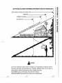
USE THIS PAGE AS A GUIDE TO DETERMINE
SLOPES
WHERE
YOU MAY NOT OPERATE
SAFELY.
SIGHT AND HOLD THIS LEVEL WITH A VERTICAL TREE
t
{3b
,_
WARNING
Do not mow on inclines with a slope in excess of 15 degrees (a rise of approximately 2-1/2 feet every 10 feet). A
riding mower could overturn and cause serious injury. If operating a walk-behind mower on such a slope, it is
extremely difficult to maintain your footing and you could slip, resulting in serious injury.
Operate RIDING mowers up and down slopes, never across the face of slopes.
Operate WALK-BEHIND mowers across the face of slopes, never up and down slopes.
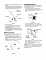
SECTION3: ASSEMBLING
YOURLAWNMOWER
RemovingUnitFromCarton
Disconnecting
SparkPlug
•
Remove staples, break glue on top flaps, or cut
tape at carton end and peel along top flap to open
carton.
•
•
Remove all loose parts, (hardware pack, grass bag,
oil bottle, bag adapter & side discharge chute).
•
Before setting up your lawn mower, disconnect the
spark plug wire from the spark plug, and ground it
against the engine. See Figure 2.
Attach rubber boot to a bolt on the engine in order
to ground.
Spark Plug
Wire
Figure 2
Figure 1
•
Cut along dotted lines and lay carton down flat.
Remove packing material.
Roll or slide unit out of carton. Check carton
•
Assembling
Handle
•
Raise the lower handle in the direction shown in
Figure 3A till it snaps into place. Do not move it to
the B position yet.
thoroughly for loose parts. See Figure 1.
NOTE: Make sure not to crimp the cable while
removing loose parts or the entire unit from the carton.
NOTE: Reference to right or left hand side of the mower
and/or front or behind the mower is observed from the
NOTE: Make sure to route the cable inside the lower
handle. Also do not crimp the cable while lifting the
handle up.
A
operating position.
ToolsRequired
1.
2.
Pair of Pliers
Funnel
HardwarePack
Identify each piece of the hardware pack as shown in
Figure 1. Part numbers shown in parentheses.
Wing Knob (712-0397)
1/4-20 (2)
B
Carriage Bolt (710-0703)
1/4-20 (2)
Figure 1
Figure 3
For shipping purposes, the hairpin clip is placed in the
outer hole of the weld pin on the lower handle.
Remove the hairpin clip from the outer hole of the
weld pin.
Using a pair of pliers, insert the hairpin clip into the
inner hole in the weld pin. Insert the carriage bolt
included in the hardware pack as illustrated below
and secure with wing knob. See Figure 4.
\
_
Right-Hand
___
Lower Handle
k_
Wing Knob
AttachingDischargeChute
Your lawn mower was shipped as a mulcher. Remove
the mulching cover and attach the side-discharge chute
for discharging grass clippings.
•
Remove three plastic wing knobs holding the
mulching cover to the deck. See Figure 6. Keep the
cover in a safe place for future use. Save wing
knobs.
Mulching
Cover
_i_rriage Bolt
_
_,
._
_'___
Hairpin Clip
Weld Pin _
'_
Figure 6
Figure 4
•
•
•
Place the side-discharge chute on the deck (in
place of the mulching cover) so that the top flange
on the discharge chute goes under the top edge of
the opening on the deck. See Figure 7.
Repeat on other side.
Raise the upper handle in the direction shown in
Figure 3B. Tighten the wing knobs which are
already on the handle.
Attach the cable to the lower handle with the two
cable ties already on the lower handle. Place posts
in holes on lower handle and pull tight on the cable
ties; cut off the extra.
Side-Discharge
AttachingStarterRope
The rope guide is already attached to the right side of
the upper handle of your mower. See Figure 5.
•
•
With the spark plug wire disconnected and
grounded, hold the blade control handle against the
upper handle, and pull the starter rope out of the
engine.
Release the blade control handle. Slip the starter
rope into the rope guide. See Figure 5.
Top Flange
goes unaer
top edge of
opening on deck
Ai]gn the slot
nere [only two
snown)
Figure 7
•
•
Align the three slots on the chute with the hardware
slots on the deck. See Figure 7.
Secure with the wing knobs earlier removed.
Tighten the wing knobs.
Lower
IMPORTANT:This unit is shipped WITHOUT GASOLINE
or OIL. Be certain to service engine with gasoline and
oil as instructed in the separate engine manual before
operating your mower.
Starter
Rope
Support
Rod
Rope
Guide
Figure 5
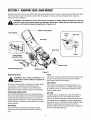
SECTION4: KNOWING
YOURLAWNMOWER
Read this operator's manual and safety rules before operating your lawn mower. Compare the illustrations in Figure
8 with your lawn mower to familiarize yourself with the location of various controls and adjustments. Save this
manual for future reference.
operator's eyes thus causing severe eye damage. Always wear safety glasses while operating the
WARNING: The operation of any lawn mower can result in foreign objects being thrown into the
mower, or while performing any adjustments or repairs on it.
_
Blade Control Handle
f
Recoil Starter
Oil Fill
Plu
Gas Tank
Grass Bag
J
J
Spark Plug
Primer
Cutting Height
Adjustment Rod
_
j
Grass Bag Adapter
Side Discharge Chute
Caster Locks
\
Mulching Cover
Figure 8
BladeControlHandle
_
safety
device.
Never
attempt
to bypassisits
WARNING:
This
control
mechanism
a
operations.
Primer
The primer is used to pump gas into the carburetor. Use
it to start a cold engine, but do not use it to restart a
warm engine after short shutdown.
CasterWheels
The blade control handle is located on the upper handle
of the mower. The blade control handle must be
depressed in order to operate the unit. Release the
blade control handle to stop the engine and the blade.
CuttingHeightAdjustmentRod
The cutting height adjustment rod is located between
the two rear high wheels.The front wheel cutting height
is determined by placing the axle rod in one of the six
height adjustment positions in each caster assembly on
the front wheels. All wheels must be placed in the same
relative position.
RecoilStarter
The recoil starter is attached to the handle. Stand
behind the unit and pull the recoil starter to start the
unit.
Your mower is equipped with caster wheels in front.
The casters can be locked in a straight ahead position
for mowing on hills, or can be left unlocked to swivel
freely on level ground.
GrassBag
The grass bag is equipped with a bag-fill indicator to
add convenience to your work. While the mower is
running, air will flow through the bag and into the "sail."
If the grass catcher is empty, air flows through easily
pushing the sail up. If the grass catcher is full, air does
not flow through it allowing the sail to fall. So the
position of the sail acts as a bag-fill indicator signifying
when to empty the grass bag.
GrassBagAdapter
MulchingCover
When installed, it allows the mower to collect clippings
in the grass bag.
When installed, the mulching cover aids in a process of
recirculating grass clippings repeatedly beneath the
cutting deck. The ultra-fine clippings are then forced
back into the lawn where they act as a natural fertilizer.
Side DischargeChute
When installed allows the mower to discharge clippings
out the side of the deck.
SECTION5: OPERATING
YOURLAWNMOWER
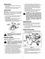
GasAndOilFill-Up
•
Oil:
•
•
•
•
Only use high quality detergent oil rated with API
service classification SF, SG or SH. Use SAE30 oil;
do not use 10W40 oil.
Clean area around fuel cap. Remove cap. See
Figure 9. Use a funnel to prevent spillage.
Pour approximately 1.5 quarts of fresh, regular
grade, unleaded gasoline slowly to the fuel tank.
IMPORTANT: Never mix engine oil with gasoline.
•
Fill oil sump and check the oil level following steps
below. See Figure 9.
a. Position the mower on level ground and
clean area around oil fill plug.
b. Remove oil fill plug and dipstick. Wipe
dipstick clean, insert it into oil fill hole and
tighten securely.
c. Remove dipstick and check oil level. If the oil
is not up to FULL mark on the dipstick, pour
recommended oil through the oil fill and
check the level again.
Install oil fill plug and dipstick, tighten securely.
Fill tank to 1/2" below the bottom of the filler neck.
Wipe any fuel spillage. Do not fill fuel tank
completely. Provide space for fuel expansion.
StartingEngine
WARNING:
Be sure no one other than the
operator is standing near the lawn mower
while starting or operating.
Never run engine indoors or in enclosed,
poorly ventilated areas. Engine exhaust
contains carbon monoxide, an odorless
and deadly gas.
Keep hands, feet, hair and loose clothing
away from any moving parts on engine
and lawn mower.
Fill oil here
•
•
Fill g
•
Figure 9
NOTE: Although multi-viscosity oils (5W30, 10W30,
etc.) improve starting in cold weather, these multiviscosity oils will result in increased oil consumption when
used above 32°F. Check oil level more frequently to
avoid possible engine damage from running low on oil.
•
Gasoline
•
_
when
engineNever
is running
or hot.
Do not
WARNING:
fill fuel tank
indoors,
or
smoke when filling fuel tank.
10
To prevent the unit from sliding, place your foot
firmly against the tire.
Attach spark plug wire to spark plug. Make certain
the metal cap on the end of the spark plug wire is
fastened securely over the metal tip on the spark
plug.
Push primer three times. Wait about two seconds
between each push. In cold weather around 55 o F
or below, prime five times. Do not prime to restart a
warm engine after a short shutdown.
Grasp starter handle and pull rope out slowly until
engine reaches the start of compression cycle
(rope will pull slightly harder at this point). Let the
rope rewind slowly.
Pull rope with a rapid, continuous, full arm stroke.
Keeping a firm grip on the starter handle, let the
rope return to the starter slowly.
StoppingEngine
•
•
Release blade control handle to stop the engine
and the blade.
•
Disconnect spark plug wire and move away from
spark plug to prevent accidental starting.
•
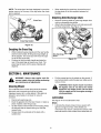
LockingCasters
IMPORTANT: If you are cutting grass on a slope, always
lock the front wheel casters of your mower for straight
ahead operation. On level ground you may leave the
casters unlocked to pivot freely.
•
•
•
WARNING: If you strike a foreign object,
stop the engine. Remove spark plug wire
from spark plug, thoroughly inspect the
mower for any damage. Repair the damage
before restarting and operating the mower.
Extensive vibration of the mower during
operation is an indication of damage. The
unit should be promptly inspected and
repaired.
To turn the mower on a slope with casters locked,
depress the upper handle and raise the front
wheels slightly.
To lock caster: Lift and place the lock pin in the
larger hole on each caster. See Figure 10.
To unlock caster: Lift and place the lock pin in the
smaller hole to allow casters to rotate freely.
HeightAdjustment
Refer to height adjustments section of this manual on
page 14 for instruction on how to adjust the cutting
height and the handle height.
Unlocked
Locked
The best mowing pattern is one that allows the
clippings to discharge towards the uncut part of the
lawn. This permits recutting of the clippings to
further pulverize them. When cutting high weeds,
discharge towards cut portion, then recut at right
angles to first direction.
For a healthy lawn, always cut off one-third or less
of the total length of the grass. Lawn should be
trimmed in fall as long as there is growth.
•
For best results in mowing, keep the cutting height
position high until it is determined which height is
best for your lawn.
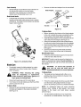
AttachingTheGrassBag
•
Figure 10
Remove three wing knobs holding the mulching
baffle or side discharge chute in place and remove
from unit. See Figure 11.
WARNING: Do not mow on slopes with
casters unlocked since the mower can
drift downhill.
Using
YourLawnMower
Your mower is designed to operate as a mulching,
bagging or a side-discharge unit.
Grass Ba(
Adapter
WARNING: Do not operate the mower
without the mulching cover, grass bag
adapter or the discharge chute properly
installed and tightly secured.
•
•
Be sure that the lawn is clear of stones, sticks, wire,
or other objects which could damage lawn mower
or engine. Such objects could be accidently thrown
by the mower in any direction and cause serious
personal injury to the operator and others.
For best results, do not cut wet grass because it
tends to stick to the underside of the mower,
preventing proper discharge of grass clippings, and
could cause you to slip and fall. New grass, thick
grass or wet grass may require a narrower cut.
Wing l
Knobs
Figure 11
•
•
11
Replace with grass bag adapter, while making
sure the front lip of adapter goes under the edge of
the deck. Secure with wing knobs previously
removed.
Lift chute door on the grass bag adapter and slide
grass bag onto the adapter. See Figure 12.
NOTE: The chute door has been designed to move the
starter rope out of the way of the bag when the chute
door is opened.
•
When replacing the grass bag, be sure the top of
the bag rests on the wire support between the
handles.
AttachingSideDischargeChute
Chute Door
•
•
Remove mulching baffle or grass bag adapter from
unit by unthreading wing knobs.
Attach side discharge chute to unit and secure with
the three wing knobs. See Figure 13.
Grass Bag Adapter
Figure 12
Emptyingthe GrassBag
•
•
While holding the grass bag by both the rear handle
and the lower handle, lift the grass bag straight up
off the adapter. The chute door will move the rope
out of the way of the bag.
Continue to hold the lower handle and raise the
rear of the grass bag up toward your chest. The
grass bag will open and the grass clippings will
disperse.
Side
Chute
Wing
Knobs
Figure
13
SECTION6: MAINTENANCE
•
connect
spark
plug wire
WARNING:
Always
stop before
engineperforming
and disany maintenance or adjustments.
Put the mower back on its wheels on the ground. If
you had put plastic under the gas cap, make sure to
remove it now.
WARNING: Never tip the mower more than
90 degrees and do not leave the mower
tipped for any length of time. Oil can drain
into the upper part of the engine causing a
starting problem.
CleaningMower
The underside of the mower deck should be cleaned
after each use to prevent any build-up of grass
clippings, leaves, dirt, or other debris. If this debris is
allowed to accumulate, it will result in rust and
corrosion.
•
•
•
•
Lubrication
Disconnect spark plug wire.
Drain the gasoline from the lawn mower, or place a
piece of plastic under the gas cap.
Tip the mower so that it rests on the housing. Keep
the side with the air cleaner facing up. Hold the
mower firmly.
Scrape clean the underside of the deck with a
suitable tool.
See Figure 14 for the lubrication chart.
Wheels
•
12
Lubricate the wheels at least once a season with
light oil or engine oil. Also, if the wheels are
removed for any reason, lubricate the surface of the
axle bolt and the inner surface of the wheel with oil.
CasterAssembly
•
•
Remove the blade and adapter from the crankshaft.
Grease fittings are provided for easy lubrication of
the swivel pins located on the front caster
assembly. Use a grease gun to lubricate the
casters every 25 operating hours or so.
Blade Adapter
Crankshaft
BladeControlHandle
•
Single-Bolt
Blade
Lubricate the pivot points on the blade control
handle and the brake cable at least once a season
with light oil. The blade control handle must operate
freely in both directions.
Blade Bell
Hex Bolt
Support
Figure 15
To ReplaceBlade
•
•
•
/
Before reinstalling the blade and the blade adapter
to the unit, lubricate the engine crankshaft and the
inner surface of the blade adapter with light oil.
Install the blade adapter on the crankshaft with the
"star" away from the engine. See Figure 15.
Place the new blade with the side marked bottom
•
(or with part number) facing away from the adapter.
Place the bell support next. Make sure to align the
tabs in the holes of the blade with the hole in the
•
bell support.
Insert the hex bolt through the blade assembly.
Figure 15 shows the correct order of assembly.
RecommendedTorque
•
IMPORTANT:The bolt, used to secure the blade to the
engine, is specially heat-treated. Do not substitute. To
order replacement bolt, refer to the Parts List section of
this manual.
Figure 14: Lubrication Chart
BladeCare
•
Follow the recommended torque for the bolt which
is 450 inch-lbs to 600 inch-lbs.
Periodically inspect the blade adapter for cracks,
especially if you strike a foreign object. Replace
when necessary.
your
unit, all
andsafe
bolts
must be
WARNING:
To nuts
ensure
operation
of
checked periodically for correct tightness.
To Sharpen Blade
_IL
•
•
blade
for sharpening
or replacement,
WARNING:
When removing
the cutting
protect hands by using heavy gloves or a
rag to grasp the cutting blade.
Disconnect spark plug wire from spark plug.
Turn mower on its side making su re that the air filter
and the carburetor are up.
To RemoveBlade
•
•
The blade can be sharpened with a file or on a
grinding wheel. Do not attempt to sharpen while
blade is on the mower.
•
Follow the original angle of grind as a guide. Make
sure that each cutting edge receives an equal
amount of grinding to prevent an unbalanced blade.
NOTE:
Remove the bolt and blade bell support which hold
the blade and adapter to the engine crankshaft.
See Figure 15.
An unbalanced
blade
will cause excessive
vibration when rotating at high speeds, may cause
damage to the mower and could break, causing
personal injury.
•
13
Test the blade by balancing it on a round shaft
screwdriver or a blade balancer. See Figure 16.
If the blade is not balanced, remove metal from the
heavy side until it balances evenly.
•
1. Insert screw driver through hole
•
2. Blade should be parallel to ground
Screw
Driver",_
Blade
_1
Ground
•
Figure 16
EngineMaintenance
•
•
•
A list of key maintenance jobs required for good
performance by the mower over the years follows
here. Follow the accompanying engine manual for
detailed list and instructions.
Change engine oil after the first two operating
hours and every 25 operating hours thereafter.
Check oil level before starting the engine.
Service the foam filter in the air cleaner every 25
hours of use and replace the paper filter component
every 100 hours. You may have to service the air
filter more frequently if you are operating the mower
under extremely dusty conditions.
Clean the engine periodically. Remove dirt and
debris with a cloth or brush. We do not recommend
the use of pressure washers or garden hose to
clean your unit.These may cause damage to
electric components, spindles, pulleys, bearings or
the engine. The use of water will shorten life of the
mower and reduce its serviceability.
Clean the spark plug and reset the gap to .030" at
least once a season or every 50 hours of operation.
Spark plug replacement is recommended at the
start of each season. Refer to the engine manual,
shipped with this unit, for correct spark plug type.
Inspect muffler periodically, and replace if
necessary. Damaged mufflers or spark arresters
can create a fire hazard. Make sure to avoid muffler
and surrounding areas while the mower engine is
hot because temperature of these areas of the
engine may exceed 150 ° F.
SECTION7: MAKINGADJUSTMENTS
•
HandleHeight
Your mower is shipped with the handle in the higher
height position. To lower the handle height, proceed as
follows.
Remove the starter rope from the rope guide.
Remove the upper handle by removing the hand
knobs and carriage bolts. Lay the upper handle out
of the way, being careful not to bend or kink the
cables.
•
•
\
Turn the lower handle around so the notch on the
bottom of the lower handle is facing forward as
shown in Figure 17. Reassemble, placing the
bottom holes in the handle over the weld pins in the
handle mounting bracket.
Reassemble the upper handle to the lower handle.
Place the hairpin clips in the inner holes in the weld
pins and attach the starter rope as instructed in the
Assembly section.
CuttingHeight
IMPORTANT:All wheels must be placed in the same
relative position. For rough or uneven lawns, move the
height adjustment lever to a higher position. This will
help stop scalping of the grass.
Notch
Lower
Handle
Front Wheel
The front wheel cutting height is determined by placing
the axle rod in one of the six height adjustment
positions in each caster assembly on the front wheels.
Figure 17
•
Remove the hairpin clips from the weld pins on the
handle brackets. Refer to Figure 4. Press out on the
legs of the lower handle. Remove lower handle
from the mower.
•
14
To adjust, remove the wing knob from the axle bolt.
See Figure 18.
Slide the axle bolt and spring washer from the
assembly and select a cutting height.
•
•
With the spring washer on the axle bolt, reinsert the
axle bolt in the square hole desired, through the
wheel assembly. See Figure 18.
Secure with wing knob previously removed.
•
•
•
Spring Washer
y
Squeeze the two adjustment rods together and pull
towards the operator. See Figure 19.
Move rods upward or downward to any one of the
six positions and reinsert. See Figure 19.
Make su re that the rear rod sits in the groove of the
new height position.
Rear Rod
Axle Bolt
Wing
knob
Rod
Figure 18
Rear Wheel
_rail
Shield
The rear wheel cutting height adjustment rod is located
between the two rear hi-wheels.
Figure 19
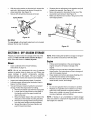
SECTION8: OFF-SEASON
STORAGE
Prepare your lawn mower for storage at the end of the
season or if the unit will not be used for 30 days or
more. Store the mower in a clean, dry area.
NOTE: When folding the handle for storage or transportation, be careful not to bend or kink the cable.
Engine
Mower
•
•
Clean underside of the mower following
instructions on page 12.
•
NOTE: We do not recommend the use of pressure
washers or garden hose to clean your unit. These may
cause damage to electric components, spindles,
pulleys, bearings or the engine. The use of water will
shorten life of the mower and reduce its serviceability.
•
•
Inspect and replace/sharpen blade, if required.
Lubricate mower following the lubrication chart in
Figure 14 of this manual.
You can fold your mower's handle for convenient
storage. Follow the steps below for folding.
a. Remove the starter rope from the rope guide.
b. Loosen the two hand knobs on the sides of
Follow recommendations in the accompanying
engine manual for off-season storage of the
engine.
Change oil if it has not been changed in the last
three months. For instructions on how to change oil,
refer to the engine manual.
Clean engine and remove any grass clippings, dirt,
or chaff from the exterior of the engine.
Remove any dirt or debris from cooling fins, air
intake screen, levers, and linkage.
Other
Do not store gasoline from one season to another.
Replace your gasoline can if it starts to rust. Rust
and/or dirt in the gasoline will cause problems.
Store unit in a clean, dry area. Do not store next to
corrosive materials, such as fertilizer.
the handle, and let the upper handle fold
down to the rear.
c.
Move the hairpin clips to the outer hole in the
weld pins on the handle mounting brackets.
d. Remove the carriage bolts and wing knobs
from the lower handle mounting brackets.
e. Spread the sides of the lower handle, and
push it forward and down.
NOTE: If storing in an unventilated or metal storage
shed, be certain to rustproof the equipment by coating
with a light oil or silicone.
15
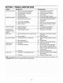
SECTION9: TROUBLE-SHOOTING
GUIDE
Problem
PossibleCause
CorrectiveAction
Engine fails to start
1.
2.
3.
4.
5.
Blade control handle disengaged
Spark plug wire disconnected
Fuel tank empty, or stale fuel
Blocked fuel line
Faulty spark plug
Engine runs erratic
1.
2.
Spark plug wire loose
Blocked fuel line or stale fuel
3.
4.
5.
Vent in gas cap plugged
Water or dirt in fuel system
Dirty air cleaner
1.
2.
Engine oil level low
Air flow restricted
1.
Spark plug gap too close
1.
Adjust gap to .030 inches.
1.
Spark plug fouled, faulty, or gap too wide
1.
2.
Dirty air cleaner
2.
Reset gap to .030 inches or replace
spark plug.
Clean air cleaner.
1.
2.
.
Engine overheats
Occasional skip
(hesitates) at high
speed
1.
2.
,3.
4.
5.
,
3.
4.
5.
I 1.
2.
Connect and tighten spark plug wire.
Clean fuel line, fill tank with clean,
fresh gasoline.
Clear vent.
Drain fuel tank. Refill with fresh fuel.
Clean air cleaner. Refer to engine
manual.
Fill crankcase with proper oil.
Clean lawn mower engine.
'
Idles poorly
Mower will not
mulch grass
1.
Tighten blade and adapter, balance
blade.
2.
3.
Bent cutting blade
Bent engine crankshaft
2.
3.
Replace blade.
Contact your nearest White dealer
1.
2.
Wet grass
Excessively high grass
1.
2.
Wait until later to cut.
Mow once at a high cutting height
then mow again at desired height.
Make a narrower cutting swath (1/2)
width. Do not cut off more than 1/3 of
the total length.
Sharpen or replace blade.
'
,
Uneven cut
Engage blade control handle.
Connect wire to spark plug.
Fill tankwith fresh, clean fuel.
Clean fuel line.
Clean, adjust gap or replace.
3.
Dull blade
3.
1.
Wheels not in same height position
1.
2.
Dull blade
2.
Place all four wheels in same relative
height position.
Sharpen or replace blade.
NOTE: For repairs beyond the minor adjustments listed above, contact an authorized MTD service dealer or call
1- (800)-800-7310 to reach a Customer Support representative.
16
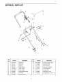
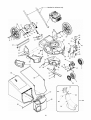
SECTION10: PARTSLIST
11
13
15
\
16
15
16
17
Ref.
No.
Part No.
Ref.
No.
Description
Part No.
Description
Hairpin Clip
10.
747-0940A
Grass Bag Support Rod
746-0883
726-0240
Wing knob
Cable Tie
11.
12.
710-1270
Housing Control
Oval C-Sunk Scr.
4.
736-0451
Saddle Washer
13.
712-0324
Hex L-Nut 1/4-20 Thd.
5.
749-0907B
Lower Handle
14.
746-1131
Control Cable, 46"
6.
749-0438D
710-1174
Carriage Bolt
7.
647-0004
Upper Handle
Deluxe Control Handle
15.
16.
712-0397
Knob, Wing, 1/4-20
8.
720-0295
Foam Grip
17.
710-0703
Carriage Screw, 1/4-20 x .75
9.
712-0429
Hex Nut, 5/16-18
1.
714-0104
2.
720-0241
3.
17
59
15
11
25
59
35
44
37 5
\
36
40
48
43
46 34
49
57 56
69
1(
68
9
61
67
m
63
28
64
J
18
65
Ref.
No.
Part No.
Description
751 B28202
Engine
Engine Shroud
2.
.734-1857
Wheel, Front Caster 7 × 2
3.
736-0105
Bell Washer .401 X .870 X .063
38.
.682-9024
4.
736-0182
Spring Washer .50 I.D. x 1.0 x .022
Flat Washer .510 x 1.0 x .060
39.
710-0260
Carriage Bolt 5/16-18 x .62
40.
711-1146
Caster Axle .374 x 2.59
Shoulder Screw .500 x 2.62:3/8 -16
Wing Knob
1.
Ref.
No.
Part No.
Description
35.
36.
782-0049
682-9020A
Deck 21"
Caster Assembly, RH
.. 37.
682-9021A
Caster Assembly, LH
.Caster Bracket Assembly, RH
5.
6.
.736-0272
738-0481A
41.
712-0397
7.
748-0377C
Blade Adapter
42.
712-3004A
8.
736-0524A
710-1257
Blade Bell Support
Hex Bolt 3/8 - 24 x 2.5 Gr. 8
43.
44.
714-0104
726-0214
11.
742-0741
647-0028
.Blade 21", Mulching
Hi-Wheel Height Adj. Support
45.
46.
.732-0306
736-0232
12.
710-1348
AB Screw 1/4-14 x .50
47.
736-0366
Flat Washer, .604 x 1.12 x .125
13.
712-3017
Hex Nut 3/8 -16
48.
736-0264
Flat Washer .330 I.D. x .630 x .06
14.
732-0845
Torsion Spring
49.
736-0931
Flat.Washer..203
15.
732-0843
Torsion Spring, RH
50.
737-3000
Lube Fitting
16.
732-0844
Torsion Spring, LH
51.
741-0685
Flange Bearing
17.
736-0105
Bell Washer .401 x .870 x .063
747-0924
18.
738-0145
Shoulder Screw .500 x .840
53.
731-1832
Lock Pin, Front Wheel
Discharge Chute
19.
747-0971
Handle, Height Adjustment
54.
731-1833
Mulching Cover
20.
750-1090
Spacer .500 x 1.0 x .600
55.
731-1886
Hubcap
21.
782-0572
Height Adj. Bracket, RH
56
710-0653
Hex Screw, TT 1/4-20 x .375
22.
682-3054
Handle Bracket Ass'y, RH
57.
710-0969
23.
24.
682-3055
710-1348
Handle Bracket Ass'y, LH
AB Screw 1/4-14
58.
731-1828
Self-tapping Screw (Hi-Lo)
Rear Baffle
734-1860
Hi-Wheel 14 X 2
731-1874
Chute Door
732-0819
Torsion Spring
.
10.
Flange Nut 5/16-18 Gr.5
.Hairpin Clip
Push Cap
Compression Spring
Wave Washer .530 I.D. x .780 O.D.
I.D. x .403 x .040
i
725-0157
26.
27.
Trail Shield
.731-1901
61.
Push Cap
28.
Pivot Rod
29.
64.
731-1713B
30.
710-0654A
TT Screw 3/8 -16 x 1.00
65.
631-0066
Chute Assembly
31.
710-0703
Carriage Screw 1/4-20 x .75
66.
631-0071
Top Discharge Grass Bag Cover
32.
712-0397
Wing knob
67.
726-0106
Cap Nut
33.
726-0233
34.
682-9026
Push Nut
Discharge Chute
747-0937
i
Grass Bag Frame
i
Caster Bracket Assembly, LH
69.
19
664-01086
Grass Bag, Sail w/Sprig
MANUFACTURER'S
LIMITED WARRANTY
FOR:
YaRD-MaN )
The limited warranty set forth below is given by MTD LLC with
respect to new merchandise purchased and used in the
United States, its possessions and territories.
MTD LLC warrants this product against defects for a period of
two (2) years commencing on the date of original purchase
and will, at its option, repair or replace, free of charge, any
part found to be defective in materials or workmanship. This
limited warranty shall only apply if this product has been
operated and maintained in accordance with the Operator's
Manual furnished with the product, and has not been subject
to misuse, abuse, commercial use, neglect, accident,
improper maintenance, alteration, vandalism, theft, fire,
water, or damage because of other peril or natural disaster.
Damage resulting from the installation or use of any
accessory or attachment not approved by MTD LLC for use
with the product(s) covered by this manual will void your
warranty as to any resulting damage.
Normal wear parts or components thereof are subject to
separate terms as follows: All normal wear parts or
component failures will be covered on the product for a period
of 90 days regardless of cause. After 90 days, but within the
two year period, normal wear part failures will be covered
ONLY IF caused by defects in materials or workmanship of
OTHER component parts. Normal wear parts and
components include, but are not limited to: batteries, belts,
blades, blade adapters, grass bags, rider deck wheels, seats,
snow thrower skid shoes, shave plates, auger spiral rubber,
and tires.
HOW TO OBTAIN SERVICE: Warranty service is available,
WITH PROOF OF PURCHASE, through your local authorized
service dealer. To locate the dealer in your area, check your
Yellow Pages, or contact MTD LLC at P.O. Box 361131,
Cleveland, Ohio 44136-0019, or call 1-800-800-7310 or log
on to our Web site at www.mtdproducts.com.
This limited warranty does not provide coverage in the
following cases:
a.
b.
C.
The engine or component parts thereof. These items
carry a separate manufacturer's warranty. Refer to
applicable manufacturer's warranty for terms and
conditions.
Log splitter pumps, valves, and cylinders have a sepa
rate one year warranty.
Routine maintenance items such as lubricants, filters,
blade sharpening, tune-ups, brake adjustments, clutch
adjustments, deck adjustments, and normal
deterioration of the exterior finish due to use or
d.
e.
f.
g.
MTD LLC does not extend any warranty for products
sold or exported outside of the United States, its
possesions and territories, except those sold through
MTD LLC's authorized channels of export distribution.
Parts that are not genuine MTD parts are not covered
by this warranty.
Service completed by someone other than an
authorized service dealer is not covered by this
warranty.
Transportation charges and service calls are not
covered.
No implied warranty, including any implied warranty of
merchantability of fitness for a particular purpose,
applies after the applicable period of express written
warranty above as to the parts as identified. No other
express warranty, whether written or oral, except as
mentioned above, given by any person or entity,
including a dealer or retailer, with respect to any product,
shall bind MTD LLC. During the period of the warranty,
the exclusive remedy is repair or replacement of the
product as set forth above.
The provisions as set forth in this warranty provide the
sole and exclusive remedy arising from the sale. MTD
LLC shall not be liable for incidental or consequential
loss or damage including, without limitation, expenses
incurred for substitute or replacement lawn care services
or for rental expenses to temporarily replace a warranted
product.
Some states do not allow the exclusion or limitation of
incidental or consequential damages, or limitations on how
long an implied warranty lasts, so the above exclusions or
limitations may not apply to you.
In no event shall recovery of any kind be greater than the
amount of the purchase price of the product sold. Alteration
of safety features of the product shall void this warranty.
You assume the risk and liability for loss, damage, or injury to
you and your property and/or to others and their property
arising out of the misuse or inability to use the product.
This limited warranty shall not extend to anyone other than the
original purchaser orto the person for whom it was purchased
as a gift.
HOW STATE LAW RELATES TO THIS WARRANTY:
This
limited warranty gives you specific legal rights, and you may
also have other rights which vary from state to state.
exposure.
MTD LLC, P.O. BOX361131CLEVELAND,OHIO44136-0019; Phone:1-800-800-7310