1
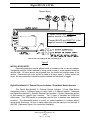
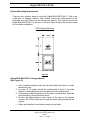
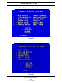
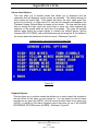
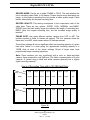
Digital
BUS-WATCH®
User Manual
Installation Manual
Radio Engineering Industries, Inc.
6534 L Street
Omaha, Nebraska 68117
402-339-2200
Digital BUS-WATCH®
Table of Contents
LIST OF FIGURES
4
INTRODUCTION
5
MAIN SYSTEM OVERVIEW
5
EXPANDED SYSTEMS OVERVIEW
6
REI DVR CAMERA SYSTEM OPTIONS
7
DVR FEATURES
8
System Components
8
Initial Set Up
8
Hard Drive Loading and Unloading
9
System Start-Up
9
Automatic Hard Drive Heater
9
Digital BUS-WATCH® IV Security Cabinet Mounting
10
Long Term Storage
10
SYSTEM INSTALLATION
11
System Wiring
11
Digital BUS-WATCH® IV External Record Indicator / Event Mark Button Harness
12
Digital BUS-WATCH® IV GPS Antenna Module Harness
13
Digital BUS-WATCH® IV Vehicle Sensor Options Harness DVR Connection Instructions
15
Speedometer Harness Wiring Instructions
15
Digital BUS-WATCH® IV Vehicle Sensor Options Harness Vehicle Connections
16
On-Screen Information with Vehicle Sensor Options Harness
16
Physical Mounting Requirements
17
Digital BUS-WATCH® IV Hanging Mount
17
Mount Conversion
19
Digital BUS-WATCH® IV Floor Mount Installation
19
Camera Placement
21
DIGITAL BUS-WATCH® IV BASIC OPERATION
22
Hard Disk Drive Modules
22
Front Panel
24
2
Radio Engineering Industries, Inc.
640333
Rev 0 -- 1/1/2006
Digital BUS-WATCH®
MENU SYSTEM
25
Main Menu Screen
26
System Information Screen
27
Set Time/Date Screen
28
Audio Control Menus
30
Audio Channel Selection Menu
31
Playback Volume Menu
31
Set Vehicle ID Screen
32
Calibration Screen
32
Speedometer Calibration Screen
33
Speedometer Signal Levels Screen
34
Screen Adjustment Screen
34
Center On-Screen Display
35
Adjust Width
36
Capture Image Screen
36
On Screen Display Options
40
Main Display Options
41
GPS Display Options
42
Vehicle Sensor Options
42
Sensor Display Options
43
Sensor Level Options
45
Playback Options
45
Recording Options
46
Overwrite Menu
48
Alarm Record Menu
49
Alarm Trigger Options
49
Alarm Record Options
50
Audible Alarm Options
51
Set Record Timers Screen
53
DIGITAL BUS-WATCH® IV CD-ROM
54
DIGITAL BUS-WATCH® IV SYSTEMS RELATED PART NUMBERS
55
TYPICAL CAMERA LENS VIEWING ANGLES
57
SPECIFICATIONS
58
3
Radio Engineering Industries, Inc.
640333
Rev 0 -- 1/1/2006
Digital BUS-WATCH®
LIST OF FIGURES
Figure 1 ……...………. BUS-WATCH® IV Components……...……...……...……...……...……...……....…. 5
Figure 2 ……...………. System Drawing ………………….……...……...……...……...……......…...……...… 6
Figure 3 ……...………. Camera System Options ...………….……...……...……...……...……...……...……. 7
Figure 4 ……...………. Initial Drive Warming Screen Shot …...……….……...……...……...…......……..... 10
Figure 5 ……...………. System Wiring ………………………...……...……...……...……...……......…...….. 12
Figure 6 ……...………. Event Harness Connection ..…..…………...……...……...……...……...……...….. 13
Figure 7 ……...………. GPS Antenna Harness Connection……….……...……...……...……...……...….... 13
Figure 8 ……...………. Vehicle Sensor Options Harness Mounting …………...……...……...……...…….. 14
Figure 9 ……...………. DVR Physical Mounting ……...……...……...……...……...……...……...…………. 17
Figure 10 …….....……. Under Seat Mounting ……….………...……...……...……...……...……...……....... 18
Figure 11 …….....……. DVR Cabinet Modification …………...……...……...……...……...……...……........ 19
Figure 12 …….....……. DVR Floor Mounting .…... ……...……...……...……...……...……...……...…........ 20
Figure 13 …….....……. Camera Connection and Placement .………………...……...……... ……...……... 21
Figure 14 ……...……… Potential Multiple Camera Placement Options .....…. ……...……...……...…...... 21
Figure 15 ……...……… Hard Drive Splash Page ..….……...……...……...……...……...……...…….....…. 23
Figure 16 ……...……… Front Panel Keypad ..…...………...……...……...……...……...……...……......….. 24
Figure 17 ……...……… Main Menu Screen Shot ..…….…………...……...……...……...……...……..…… 26
Figure 18 ……...……… System Information Page Screen Shot ……...……...……...……...…….....…….. 28
Figure 19 ……...……… Time/Date Menu Screen Shot ……...……...……...……...……...……...…........… 28
Figure 20 ……...……… 2006 DST Trigger Screen Shot ……...……...……...……...……...…….....…....... 29
Figure 21 ……...……... 2007 DST Trigger Screen Shot ..…….……...……...……...……...……......…....... 30
Figure 22 ……...……... Audio Control Menus Screen Shot ……...……...……...……...……...…....…........ 30
Figure 23 ……...……... Audio Channel Selection Menu Screen Shot ……...……...……...…….……....… 31
Figure 24 ……...……... Playback Volume Menu Screen Shot ……...……...……...……...……..……........ 31
Figure 25 ……...……... Set Vehicle ID Page Screen Shot ……...……...……...……...……......…...…….... 32
Figure 26 ……...……... Calibration Menu Screen Shot ……...……...……...……...……...……..……..…… 33
Figure 27 ……...……... Speedometer Calibration Page Screen Shot ……...……...…….....…...……...…. 33
Figure 28 ……...……... Speedometer Signal Levels Screen Shot ……...……...……...….....……....…..... 34
Figure 29 ……...……... Screen Adjustment Page Screen Shot ……...……...……...……..……...……...... 35
Figure 30 ……...……... Center OSD Page Screen Shot ……...……...……...……...……..……...……...… 35
Figure 31 ……...……... Adjust Screen Width Page Screen Shot ……...……...……......…...……...…….... 36
Figure 32 ……...……... Capture Image Page Screen Shot ……...……...……...……..……...……...……... 36
Figure 33 ……...……... PC Viewer Function Menu Screen Shot ……...……...…….……...…….....……... 37
Figure 34 ……...……... PC Remote Control Bar Screen Shot ……...……...……..……...……..…...…...… 38
Figure 35 ……...……... Remote Control Buttons Screen Shot ……..……………..…..……...……..……… 39
Figure 36 ……...……... On-Screen Display Options Screen Shot ……...……...…......……...……..……… 40
Figure 37 ……...……... Main Display Options Screen Shot ……...……...……...…….……...…..………… 41
Figure 38 ……...……... GPS Display Options Screen Shot ……...……...……...……..……...……...….…. 42
Figure 39 ……...……... Vehicle Sensor Options Screen Shot ……...……...……...…......……....…...……. 43
Figure 40 ……...……... Vehicle Sensor Display Options Screen Shot – School Bus Settings …....….…. 43
Figure 41 ……...……... Vehicle Sensor Display Options Screen Shot – Transit Settings …….....…….… 44
Figure 42 ……...……... Vehicle Sensor Display Options Screen Shot – Custom Settings …….......….… 44
Figure 43 ……...……... Vehicle Sensor Input Level Options Screen Shot ……..................……....…....… 45
Figure 44 ……...……... Playback Search Options Page Screen Shot ……...……...……...…….....…....… 46
Figure 45 ……...……... Recording Options Page Screen Shot ……...……...……...……...…….....…....… 46
Figure 46 ……...……... Hours of Recording Time with a 120 GB Hard Drive ……...……...……....…....… 47
Figure 47 ……...……... Overwrite Menu Screen Shot ……...……...……...……...……...……...…..…....… 48
Figure 48 ……...……... Alarm Recording Menu Screen Shot ……...……...……...……...……...……….… 49
Figure 49 ……...……... Alarm Trigger Options Screen Shot ……...……...……...……...…….........…....… 49
Figure 50 ……...……... Alarm Record Options Screen Shot ……...……...……...……...……...…..…….… 50
Figure 51 ……...……... Audible Alarm Options Screen Shot ……...……...……...……...…….........…....… 51
Figure 52 ……...……... Record Timers Page Screen Shot ……...……...……...……...……...…….…....… 53
Figure 53 ……...……... Typical Camera Lens Viewing Angles 4mm ..…...……...……...……........…….… 57
Figure 54 ……...……... Typical Camera Lens Viewing Angles 8mm ..…...……...……...……........…….… 57
4
Radio Engineering Industries, Inc.
640333
Rev 0 -- 1/1/2006
Digital BUS-WATCH®
INTRODUCTION
Thank you for purchasing the Digital BUS-WATCH® IV surveillance system by Radio
Engineering Industries, Inc. This manual is intended to provide the user with the
information required for proper installation, initial setup and explanation of the
individual programming options. If you have any questions, or need assistance,
please call:
SERVICE HOT LINE
USA & CANADA
1-877-726-4617 Toll Free
1-402-339-2200
MAIN SYSTEM OVERVIEW
The Digital BUS-WATCH® IV is a superior surveillance system specifically designed for
rugged school bus, mass transit, and all mobile applications. The system has smooth
audio playback on 2 separate channels at all frame rates, and is GPS enabled. The
system consists of an industrial grade Digital Video Recording system encased in a
tamperproof, lockable steel security cabinet and surveillance cameras of sturdy steel
housings. As an option, the Digital BUS-WATCH® IV can monitor and record vehicle
functions such as warning lamp operation, brake, vehicle speed, and two user defined
points. Figure 1 shows each component and a minimal hookup.
Figure 1
5
Radio Engineering Industries, Inc.
640333
Rev 0 -- 1/1/2006
Digital BUS-WATCH®
EXPANDED SYSTEMS OVERVIEW
Digital BUS-WATCH® IV surveillance systems are highly configurable. Figure 2 shows
a connection diagram for a fully equipped 4 camera system. To be able to switch
between different cameras based upon an external trigger (such as a door opening);
Camera Switch Devices (P/N 700462 or 710030) can be added to the system. Camera
Switch Devices and Quad Video Processors (Color P/N 700848) or (Black & White P/N
700483) can also be added to the system to be able to record and view 5 to 16 cameras
simultaneously.
DIGITAL BUS-WATCH
CAMERAS
FOUR OR MORE CAMERA SYSTEM
STANDARD
*ADD CAMERA SWITCH
DEVICE(710030) OR QUAD
PROCESSOR (700848) FOR
ADDITIONAL CAMERAS
CAMERA CABLES
OR
DOME
OR
HARD DRIVE
MODULE
WEDGE
710010
GPS ANTENNA
710000
DIGITAL BUS-WATCH
POWER CABLE
VARIOUS
SIZES
AVAILABLE
120-160GB
AUDIO
512008
30 FT.
VEHICLE SENSOR HARNESS (OPT)
VIDEO
SERIAL
VARIOUS LENS SIZES
AVAILABLE
**RCA CABLE - COMPOSITE A/V
44 FT.
EVENT RECORD MARK HARNESS (OPT)
511986
**SERIAL COMMUNICATIONS CABLE (RS-232)
**THREE VIEWING CONNECTION OPTIONS SHOWN.
CUSTOMER DETERMINES CONFIGURATION USED.
690484
LCD COLOR
VIDEO MONITOR (OPT)
AV IN
COMM
PORT
710005
DESKTOP VIEWING STATION (OPT)
**USB 2.0 CABLE
USB
PORT
USB
PORT
PENTIUM COMPUTER
(OPT)
Figure 2
6
Radio Engineering Industries, Inc.
640333
Rev 0 -- 1/1/2006
Digital BUS-WATCH®
REI DVR Camera System Options
Table showing typical Digital BUS-WATCH® IV Systems for a variety of camera numbers
Number of
Cameras
Digital BUS-WATCH®
System
Frames
Per
Second
Concurrent
Recorded Image
Resolutions
4
Digital BUS-WATCH® IV
30
4 High
5
Digital BUS-WATCH® IV +
1 Camera Switch Device
30
4 High
30
4 High
52.5
3 High +
4 Quarter
52.5
3 High +
4 Quarter
52.5
3 High +
4 Quarter
75
2 High +
8 Quarter
75
2 High +
8 Quarter
75
2 High +
8 Quarter
97.5
1 High +
12 Quarter
97.5
1 High +
12 Quarter
97.5
2 High +
8 Quarter
120
16 Quarter
6
7
8
9
10
11
12
13
14
15
16
Digital BUS-WATCH® IV +
2 Camera Switch Devices
Digital BUS-WATCH® IV +
1 Quad Video Processor
Digital BUS-WATCH® IV +
1 Quad Video Processor +
1 Camera Switch Device
Digital BUS-WATCH® IV +
1 Quad Video Processor +
2 Camera Switch Devices
Digital BUS-WATCH® IV +
2 Quad Video Processors
Digital BUS-WATCH® IV +
2 Quad Video Processors +
1 Camera Switch Device
Digital BUS-WATCH® IV +
2 Quad Video Processors +
2 Camera Switch Devices
Digital BUS-WATCH® IV +
3 Quad Video Processors
Digital BUS-WATCH® IV +
3 Quad Video Processors +
1 Camera Switch Device
Digital BUS-WATCH® IV +
2 Quad Video Processors +
2 Camera Switch Devices
Digital BUS-WATCH® IV +
4 Quad Video Processors
Figure 3
High Resolution: Full D1 (720x486)
Quarter Resolution: CIF (360x243)
7
Radio Engineering Industries, Inc.
640333
Rev 0 -- 1/1/2006
Typical Camera
Display Setup
Digital BUS-WATCH®
DVR Features
•
•
•
•
•
•
•
•
•
•
Search Video by Date, Hour, or External Event Triggers.
On screen menu system for programming options.
Hard drive heater to warm the hard drive to a safe operating temperature in
cold weather.
Non-volatile ROM and battery backed-up memory.
Ten 24-hr. programmable timers that are used to start and stop the recording
process without user (driver) intervention.
Time and date are at the bottom of the picture so detail at the top of the picture
is not hidden.
Electrically backward compatible with previous BUS-WATCH® models.
Front panel keypad for easy programming of options and features.
Audio and video jacks located on the front of Digital BUS-WATCH® IV for easy
access.
Hot swappable Hard Drive Modules for easy video retrieval and less vehicle
down time.
System Components
• Industrial grade Digital Video Recorder.
• Hard Drive Module (120-160GB)
• Slide mount bracket (part of 710000 or 710000FM).
• Low light CCD cameras – Color, Black & White, or Decoy (4-16)
• Camera to Digital BUS-WATCH® IV cables – 510781 (or other length cables).
• Digital BUS-WATCH® IV cabinet power cable - 512002 (or other length cable).
• Vehicle Sensor Options Harness – 512008
• Event Record / External Record Indicator Harness – 511986 (or other length
cables).
• GPS Antenna - 710010
• Desktop Viewing Station - 710005
Initial Set Up
The Digital BUS-WATCH® IV system will operate without any user setup with the
default settings, however, it may not show the correct time and date (Factory Set
to Central Standard Time). To set the correct date and time and to program the
system operation to your requirements, please refer to the Menu section of this
manual.
When accessing the Menu, it is necessary to connect a video monitor to the Video
jack on the front of unit. REI recommends our battery-powered 5-inch Color LCD
monitor, P/N 690484.
8
Radio Engineering Industries, Inc.
640333
Rev 0 -- 1/1/2006
Digital BUS-WATCH®
Hard Drive Loading and Unloading
Inserting the Hard Drive: Turn the hard drive key to the unlocked and off
position. Gently insert the hard drive into the bay. Turn the hard drive key to the
locked and on position.
Removing the Hard Drive: Turn the hard drive key to the unlocked and on
position. Gently remove the hard drive from the bay.
Note: The Digital BUS-WATCH® IV will not function properly if the hard drive key is in
the unlocked or off positions. If there is no hard drive present in the bay but the key is in
the locked and on position, the Digital BUS-WATCH® IV will still power up normally, the
menus can be accessed, etc.; however, the unit will not be able to record any video and
the screen will read "DISK ERROR."
System Start-Up
To start the recording process, place the system switch in the ON position (this will
be done automatically if the system switch is connected to the ignition switch and
the ignition switch is in the ON position). Upon turning the system switch ON, the
Digital BUS-WATCH® IV will commence recording.
To stop the recording process, place the system switch in the OFF position. If the
OFF DELAY option is enabled, the Digital BUS-WATCH® IV will continue to
record for the prescribed number of minutes. When the off-delay expires, the
camera and Digital BUS-WATCH® IV shut off.
Automatic Hard Drive Heater
In order to prevent the possibility of hard-drive damage during cold periods, the
Digital BUS-WATCH® IV is equipped with a temperature sensor. The heater is
activated when the temperature is below 40° F and the Digital BUS-WATCH® IV
is turned on via system switch or timer. The red LED labeled HEATER on the front
panel indicates this. The colder the temperature, the longer the heater remains on,
with a maximum of ten minutes at the coldest temperatures. During this time all
Digital BUS-WATCH® IV functions are inhibited and the camera remains unpowered. When the unit has completed its heating cycle, it will power up and
operate normally. As the temperature inside the unit drops during operation, the
heater will periodically come on to maintain a working operating temperature. The
unit can operate to temperatures below -80° F. A screen is displayed on the video
output jack on the front of the DVR displaying the temperature and the amount of
time left on the heater cycle, see figure 4. The DVR will use this time to attempt to
acquire GPS satellite signals if the GPS antenna is present in the system. A letter
‘H’ is present in the lower left hand corner of the screens whenever the hard drive
heater is on, unless that option is unselected in the Display Options Menu.
9
Radio Engineering Industries, Inc.
640333
Rev 0 -- 1/1/2006
Digital BUS-WATCH®
Initial Drive Warming Screen Shot
Figure 4
Digital BUS-WATCH® IV Security Cabinet Mounting
The Digital BUS-WATCH® IV security cabinet can be mounted in any orthogonal
orientation under a seat, in a parcel rack, on the floor, to a wall, etc. It should not
present a trip hazard or head impact hazard, nor should it interfere with the
seating, safety or comfort of the passengers. Horizontal orientation is suggested
when several installation options are available. Any other orientation besides
horizontal may slightly reduce the life of the hard drives, unless anti-shock and
vibration measures are taken during installation.
Long Term Storage
Although the Digital BUS-WATCH® IV system draws very little current in the
stand-by mode, if the system is installed but not used for an extended period of
time (longer than 2 weeks) it is recommended that the power be disconnected
from the DVR to avoid draining the vehicle battery. The DVR internal clock will
hold time and date for up to 10 years sitting on a shelf, and the daylight savings
time functions will kick in upon re-initialization when power is applied.
10
Radio Engineering Industries, Inc.
640333
Rev 0 -- 1/1/2006
Digital BUS-WATCH®
System Installation
WARNING
DISCONNECT VEHICLE BATTERY VOLTAGE BEFORE
INSTALLING SYSTEM WIRING
WARNING
DISCONNECT POWER TO THE DIGITAL BUS-WATCH® IV
BEFORE JUMP STARTING VEHICLE
System Wiring
Note: All cables should be hidden from view.
For the basic system (shown in Figure 5), there are five cables, one power (P/N 512002
– 16 Feet, or 512001 – 35 Feet) and 4 camera (P/N 510781 or any different length
cable). For external record indication, and alarm/event marking, the Record Indicator /
Event Mark Button Harness (P/N 511986) is available (shown in Figure 6). The GPS
Harness (P/N 710010) is used for satellite location and movement information (shown in
Figure 7). For additional vehicle monitoring, the BUS-WATCH® IV Vehicle Sensor
Options harness (P/N 512008) is available (shown in Figure 8)
Connect the camera(s) using cable P/N 510781, or equivalent. There is no specific
orientation for camera cables to be installed. If multiple types of cameras are installed
in a single system, be careful to note which cameras are located where. Use lenses
with more magnification (8mm) for to bring objects closer that are far away. Use lenses
with less magnification (4mm) for wide angle viewing.
Connect power using cable P/N 512002, or equivalent. The black wire connects to the
negative terminal of the battery. The green wire (labeled 12V Battery) connects directly
to the positive terminal of the battery. The green wire should be fused at 10 Amps if
using a 7 or more camera system with a Quad Video Processor (P/Ns 700483 or
700848). See Figure 5.
Connect any Quad Video Processors (P/Ns 700483 or 700848) or Camera Switching
Devices (P/N 700462 or 710030) as needed for multiple camera systems.
IF THE SYSTEM OPERATES IN THE MANUAL RECORD MODE, connect the red wire
(labeled 12V SW), to the switched side of the ignition switch. The red wire should be
fused at 1 A. The red wire is ignored if the system is in TIMER record mode.
11
Radio Engineering Industries, Inc.
640333
Rev 0 -- 1/1/2006
Digital BUS-WATCH®
System Wiring
*Connect GREEN wire DIRECTLY to the
positive terminal of the battery.
*Connect BLACK wire DIRECTLY to the
negative terminal of the battery.
Note: Green wire fused @ 7A; Red wire fused @ 1 A
Figure 5
INSTALLATION NOTE:
Exposed connectors may be placed inside of connector box on security cabinet.
Tampering could be further reduced by using metal conduit to route exposed wires into
vehicle body. All wires should be protected from the inside and outside areas of the
vehicle. Convoluted split loom should be used in all other areas to further protect the
wires. All wire connections should be splice soldered and insulated or lugged.
Digital Bus-Watch® IV External Record Indicator / Event Mark Button Harness
The Digital Bus-Watch® IV External Record Indicator / Event Mark Button
Harnesses come in 2 different types of switch, both in 2 different lengths. Reference
the Digital Bus-Watch® IV Systems Related Part Numbers – System Harnesses section
of this manual for specific part numbers. The 2 types of switches are OEM and
Aftermarket. The OEM switch is rectangular and fits into a standard size dashboard
knockout. The Aftermarket switch is round, for easier installation in vehicles without
spare switch knockouts. All four of these cables plug into the same port on the back of
the DVR. Reference Figure 6 for connection illustration.
12
Radio Engineering Industries, Inc.
640333
Rev 0 -- 1/1/2006
Digital BUS-WATCH®
External Record Indicator / Event Mark Button Harness Connection
Figure 6
Digital Bus-Watch® IV GPS Antenna Module Harness
The Digital Bus-Watch® IV GPS Antenna Module Harness plugs into the back of
the DVR as shown in Figure 7. Digital Bus-Watch® IV GPS Antenna Module will track
up to twelve satellites at a time while providing one-second navigation updates and low
power consumption. The GPS Antenna Module is housed in a black, water-resistant
case and designed to withstand rugged operating conditions. Information provided to
the DVR system include longitude, latitude, speed, heading, date, and time. Internal
memory backup allows the GPS Antenna Module to retain critical data such as satellite
orbital parameters, last position, date, and time to reduce valid data acquisition time.
GPS Antenna Harness Connection
Figure 7
13
Radio Engineering Industries, Inc.
640333
Rev 0 -- 1/1/2006
Digital BUS-WATCH®
Digital Bus-Watch® IV Vehicle Sensor Options Harness Vehicle Connection
Vehicle Sensor Options Harness Wiring
FROM
FLASHER
FROM
FLASHER
FROM
FLASHER
FROM
FLASHER
FROM
FLASHER
(Optional) Vehicle Sensor Options
Harness (Shown as School Bus)
FROM BRAKE
PEDAL SWITCH
Figure 8
The BUS-WATCH® IV Vehicle Sensor Options Harness (shown in Figure 8)
connects to various locations in the vehicle to provide on-screen information
regarding vehicle performance. Many vehicles have different sets of signals that can
be monitored. Three levels of on-screen display are available to the installer: School
Bus, Transit, and Custom.
The default School Bus monitored points in the vehicle are:
• Vehicle speed
• Brake activation
• Amber warning lamp operation
• Red warning lamp operation
• Stop arm lamp operation
• Optional points with AUX 1 & AUX 2 (Aux 1 & Aux 2 are user-defined and
may be used to monitor points such as turn signals, rear and front doors, etc.)
The default Transit monitored points in the vehicle are:
• Vehicle speed
• Brake activation
• Warning lamp operation (De-acceleration Lights)
14
Radio Engineering Industries, Inc.
640333
Rev 0 -- 1/1/2006
Digital BUS-WATCH®
•
•
•
•
Turn signals
Front door switch operation
Back door switch operation
Optional point with Auxiliary (Aux 1 is user-defined and may be used to
monitor points such as wheelchair lifts, inertia sensors, etc.)
The Custom vehicle sensor option allows for most other situations. The letters that
appear on the screen are settable through the menu system. The default settings are:
• Vehicle speed
• R - Red wires
• Y - Yellow wires
• L - Blue wire
• B - Brown wire
• W - White wire
• P - Purple wire
When using these options, the DEFAULT condition is that the Digital BUS-WATCH®
IV considers a low voltage (or ground) the OFF state. A high voltage (5-15 VDC) is
interpreted as the ON state. To switch the polarity of these signals, reference the
Vehicle Sensor Levels Options menu page as described in that section of the
manual.
BUS-WATCH® IV Vehicle Sensor Options Harness DVR Connection Instructions
Install the BUS-WATCH® IV Vehicle Sensor Option Harness (see Figure 8) into the
security cabinet.
1. Remove the 2 mounting screws connecting the conduit box to the DVR.
2. Insert the BUS-WATCH® IV Vehicle Sensor Options Harness by plugging it
into place.
3. Route the excess harness through the provided hole
4. Assemble the connector box back onto the DVR.
Speedometer Harness Wiring Instructions
Refer to the vehicle service manual for speedometer type, exact wire
location, and transmission manufacturer warnings.
The BUS-WATCH® IV speedometer input wires are designed to be spliced directly onto
the transmission speedometer transducer wires. In some installations, this may not be
possible (i.e. mechanical speedometer, transmission manufacturer warnings, etc.). The
BUS-WATCH® IV Vehicle Speed Sensor Kit (P/N 750086) may be required.
15
Radio Engineering Industries, Inc.
640333
Rev 0 -- 1/1/2006
Digital BUS-WATCH®
BUS-WATCH® IV Vehicle Sensor Options Harness Vehicle Connections
(Shown as School Bus)
WIRE COLOR
(2) YELLOW
(2) RED
BLUE
BROWN
WHITE
VIOLET
WIRE DESCRIPTION
RIGHT & LEFT YELLOW WARNING LAMP BANK
RIGHT & LEFT RED WARNING LAMP BANK
STOP ARM LAMP
BRAKE PEDAL LAMP
AUX SIGNAL 1
AUX SIGNAL 2
Yellow Warning Lamps
Connect the YELLOW wires to each of the Warning Lamp Flashers’ Yellow lamp
outputs.
Red Warning Lamps
Connect the RED wires to each of the Warning Lamp Flashers’ Red lamp outputs.
Stop Arm Lamps
Connect the BLUE wire to the switched side of the top stop arm lamp.
Brake Lamp
Connect the BROWN wire to the switched side of one brake lamp.
On-Screen Information with BUS-WATCH® IV Vehicle Sensor Options Harness
The Digital BUS-WATCH® IV Surveillance system, when equipped with the BUSWATCH® IV Option Harness, will display information on-screen when the vehicle’s
monitored switches are activated and signals are applied to the monitored sensors.
ACTIVE SWITCH OR SIGNAL
BRAKE APPLIED
STOP ARM DEPLOYED
LEFT YELLOW WARNING LAMPS ON
(SEE NOTE 1)
RIGHT YELLOW WARNING LAMPS ON
(SEE NOTE 1)
LEFT RED WARNING LAMPS ON
(SEE NOTE 1)
RIGHT RED WARNING LAMPS ON
(SEE NOTE 1)
SPEEDOMETER
(SEE NOTE 2)
ON-SCREEN DISPLAY
B
S
*Y
Y*
*R
R*
XX
MPH
NOTES:
1.
2.
The “*” symbols will alternately appear on each side of the “Y” or “R” in concert with the active lamp
bank.
The XXs represent the vehicle speed (i.e. 35).
16
Radio Engineering Industries, Inc.
640333
Rev 0 -- 1/1/2006
Digital BUS-WATCH®
Physical Mounting Requirements
There are two common ways to mount the Digital BUS-WATCH® IV. First is the
under-seat, or hanging, method. This method mounts the slide bracket to the
underside of a seat. Second is the floor-mount method. This method mounts the
Digital BUS-WATCH® IV to the floor of the bus. Figure 9 shows the minimum area
for the system installation.
DVR Physical Mounting
Figure 9
Digital BUS-WATCH® IV Hanging Mount
(See Figure 10)
1. Find a suitable location under the first seat behind the driver or under
the driver’s seat.
2. An area 15-1/2 inches should be unobstructed in front of the slide
bracket to allow sliding the security cabinet onto the slide bracket.
3. If necessary modify the positions of the tower, connector box, and slide
rails according to the instructions above.
4. Position the slide bracket on the frame of the seat in the desired
location. Drill 5/16th inch holes through the frame using the bracket as
a guide.
5. Attach slide bracket to seat frame using nuts and bolts.
17
Radio Engineering Industries, Inc.
640333
Rev 0 -- 1/1/2006
Digital BUS-WATCH®
Note:
Use clamps to attach slide bracket to the under-seat location if necessary.
Ensure stable mounting for proper DVR operation. DVR must be solid to vehicle frame.
Under Seat Mounting
Figure 10
18
Radio Engineering Industries, Inc.
640333
Rev 0 -- 1/1/2006
Digital BUS-WATCH®
Mount Conversion
Digital BUS-WATCH® IV Cabinet Modification
(See Figure 11)
Reverse the placement of the slide rails with screws and washers from top to
bottom of the Digital BUS-WATCH® IV.
DVR Cabinet Modification
Figure 11
Digital BUS-WATCH® IV Floor Mount Installation
Find a suitable location to mount the slide bracket on the floor. The Digital BUSWATCH® IV should not present a trip hazard or head impact hazard and should
not interfere with the seating, safety, or comfort of the passengers.
1. An area 15 and 1/2 inches should be unobstructed in front of the slide bracket
to allow sliding the Digital BUS-WATCH® IV onto the bracket.
2. Position the slide bracket on the floor and drill four 3/16th inch holes into the
floor using the mounting holes as a guide.
3. Set aside the slide bracket. Position four rubber shock mounts over the pilot
holes.
4. Place the slide bracket over the rubber shock mounts. Align the mounting holes
to the center of the shock mounts.
5. Secure slide bracket to the floor using four lag bolts.
6. Carefully slide the cabinet onto the slide bracket being sure to check alignment
of the connector. Lock to secure.
19
Radio Engineering Industries, Inc.
640333
Rev 0 -- 1/1/2006
Digital BUS-WATCH®
DVR Floor Mounting
Figure 12
20
Radio Engineering Industries, Inc.
640333
Rev 0 -- 1/1/2006
Digital BUS-WATCH®
Camera Placement
The Digital BUS-WATCH® IV cameras can be mounted anywhere in the vehicle, unless
this does not give a stable mount or it vibrates excessively. Outdoor cameras should be
used for exterior placement.
Camera Connection and Placement
Figure 13
Potential Multiple Camera Placement Options
4 CAMERAS
INTERIOR
4 CAMERAS
EXTERIOR
Figure 14
21
Radio Engineering Industries, Inc.
640333
Rev 0 -- 1/1/2006
Digital BUS-WATCH®
Digital BUS-WATCH® IV Basic Operation
The Digital BUS-WATCH® IV functions somewhat like a VCR, except that the recorded
video is stored on the hard drive, rather than on a video tape. To view the recorded
video or to access the MENU functions, connect a monitor to the Digital BUS-WATCH®
IV using the front jacks labeled AUDIO and VIDEO. The end user supplies the monitor
and the cable to connect the monitor. The Digital BUS-WATCH® IV has several modes
of operation.
SLEEP mode: In a mobile, battery-powered application, it is critical to minimize power
consumption to prevent draining the vehicle battery, therefore, whenever the unit is not
recording, it automatically enters SLEEP mode. In SLEEP mode, the unit's power
consumption is minimal. The red LED on the Power Switch on the front panel is off
when the unit is in SLEEP mode. Menu access is available in this mode.
RECORD mode: While the unit is actively recording video, it is in RECORD mode. The
red LED on the Power Switch is on, and the green LED near the REC button is on. The
unit can be placed in RECORD mode in one of three ways: system switch,
programmable timer, and pressing the REC button.
PLAYBACK mode: While the unit is playing back recorded video, it is in PLAYBACK
mode. The red LED on the Power Switch is on. When the unit is PLAYBACK, the onscreen display will read PLAY and either "(-" or "-)". This indicates the direction the
video is playing, forward or backward. The direction can be switched by the FF or REW
buttons.
MENU mode: The MENU mode can be activated any time the Power Switch is turned
on by pressing the MENU button. In the MENU mode, the unit's settings and options
can be accessed. The MENU mode operations are described below. The DVR does not
record when in the MENU mode.
MONITOR mode: When the Digital BUS-WATCH® IV is active, but not in RECORD,
MENU, or PLAYBACK mode, it is in MONITOR mode. The live video from the VIDEO
input is displayed on the monitor.
Hard Disk Drive Modules
Digital BUS-WATCH® IV Hard Drive Modules only work with Digital BUS-WATCH® IV
Systems. Audio & Video recorded on a REI Digital BUS-WATCH® IV DVR can only be
played back on a REI Digital BUS-WATCH® IV DVR or Viewing Station. Version ΙV
DVRs record Event Information on the Hard Drives as well as 4 channels of Audio &
Video. When swapping hard drives between older versions of the Digital BUSWATCH® Systems, the video will pause on playback and basically keep going until the
DVR or Viewing Station can recognize the video. If 30 minutes of video is recorded onto
22
Radio Engineering Industries, Inc.
640333
Rev 0 -- 1/1/2006
Digital BUS-WATCH®
the drive with another system, the unit will pause for 30 minutes of normal play until
valid video can be presented. Fast forwarding through the 30 minutes of video will
reduce the amount of pause time. It is not recommended to swap drive between old
and new systems, as the results during playback will not be as intended. The drives are
easily identifiable as to which DVRs they belong to by the color of the face of the Hard
Drive and the DVR or the Viewing Station. Black was used for earlier versions of the
DVRs; Blue is used for this system.
REI Splash Page
REI Digital BUS-WATCH® IV Hard Drives act much as VCR tapes for recording
of Video and Audio, but with much more storage space. One other primary difference is
‘Instant Rewind Time’. Because of the ability of the DVR during playback to play from
the ‘End’ of the drive to the ‘Beginning’ of the drive without pause, leaving the user to
not be sure if they had viewed all of the video on the drive or not, it became necessary
to mark the physical beginning and ending of the drive. This is shown as the REI
Splash Page. Reference Figure 15.
REI Hard Drive Splash Page
Figure 15
The Splash Page shown above is displayed whenever the DVR is playing
through the physical address 0 of the drive. The Splash Page is not set at the mark
between the oldest and newest video, know as the Current Drive Record Marker. When
viewing the video, the Splash Page will appear at some point in the video. Pressing
23
Radio Engineering Industries, Inc.
640333
Rev 0 -- 1/1/2006
Digital BUS-WATCH®
PLAY, FF, or REW on the face of the DVR or Viewing Station will take the playback
through to the next or previous frame. No frames are dropped because of appearance
of this page. In the event that the Splash page appears in the middle of the event that is
being viewed, the Splash Page can be taken out of the video event during the process
of transferring the video to a computer file. Call REI Technical Support for special
instructions on this topic at 1-877-726-4617.
Front Panel
The user controls the functions of the Digital BUS-WATCH® IV with the buttons on the
front panel. (See Figure 16)
Front Panel Keypad
Figure 16
Controls:
•
MENU CONTROLS
• MENU - Brings up the System Control menu.
• EXIT - Exits the current menu or function.
• SEL - Selects the current menu setting. Functions much like an ENTER
key. If the unit is in SLEEP mode, pressing this button causes it to wake
up and enter RECORD mode. If the SYSTEM SWITCH is off, pressing this
button again puts the unit back into SLEEP mode.
• Directional Arrows - These buttons are used to navigate the menus.
24
Radio Engineering Industries, Inc.
640333
Rev 0 -- 1/1/2006
Digital BUS-WATCH®
OSD – This button brings up and removes the overlaid status On Screen
Display. The overlaid status On Screen Display is not permanently
recorded to the hard drive, as opposed to the time and date display which
is recorded to the drive.
• ZOOM – Toggles on and off the zoom mode functionality.
FUNCTION CONTROLS
• PLAY - Plays back recorded video. Begins playback at the last recorded image.
• REC - Starts recording. Recording is indicated a green LED near this button.
• STOP - If the unit is recording, this button stops the recording. If the unit is
playing, this button acts as a PAUSE. Pressing this button while PAUSED stops
playback and puts the unit in Monitor Mode.
• FF - If the unit is playing, this button FAST FORWARD SCANS through the
recorded video. Pressing this button several times increases the scanning speed.
• REW - If the unit is playing, this button REWIND SCANS through the recorded
video. Pressing this button several times increases the scanning speed.
• STEP REV - If the unit is in play mode and paused, this button moves the video
back one image.
• STEP FWD - If the unit is in play mode and paused, this button moves the video
forward one image.
CAMERA CONTROLS
• CH SEL - This button selects through the available individual camera views.
• QUAD – This button changes the video output display back to the 4 channel
quad display.
VIDEO CONTROLS
• DATE HOUR – If the unit is in play mode and paused, this selects between date
search and hour search modes.
• ALARM – If the unit is in play mode and paused, this selects the alarm search
mode.
•
•
•
•
Menu System
The menu system allows the user to set and save the system operating parameters.
Connect a monitor to the Digital BUS-WATCH® IV using the front jacks labeled AUDIO
and VIDEO. To activate the menu system, press the MENU button. The first screen that
appears is the Main Menu.
25
Radio Engineering Industries, Inc.
640333
Rev 0 -- 1/1/2006
Digital BUS-WATCH®
Main Menu Screen
The Main Menu Screen has several different options used to configure the system's
operating parameters. Use the arrow keys to move the cursor to the desired line and
press SEL to execute the desired command. See Figure 17.
Main Menu Screen Shot
Figure 17
FACTORY DEFAULT
Changes the DVR setting back to the original factory settings.
SYSTEM INFORMATION
Shows the temperature and voltage extremes, record time, and other DVR
information.
TIME/DATE MENU
Used to set the time, date, and Daylight Saving time settings.
AUDIO CONTROL MENUS
Allows the user to set the output volume and input audio paths.
SET VEHICLE ID
Used to program this specific unit's Vehicle ID # or description.
CALIBRATION
Allows the user to calibrate the speedometer and voltmeter functions.
CAPTURE IMAGE
Used when downloading digital images to a PC via the serial port.
26
Radio Engineering Industries, Inc.
640333
Rev 0 -- 1/1/2006
Digital BUS-WATCH®
DISPLAY OPTIONS
Allows the user to determine what information is recorded onto the screen.
PLAYBACK SEARCH OPTIONS
This screen directs users to specific portions of the video for fast retrieval.
RECORDING OPTIONS
Allows the user to change frame rates and compression levels.
Factory Default
If this item is selected, the system's internal settings will be set to the factory
defaults. This includes:
•
•
•
•
•
•
•
•
•
•
•
•
•
•
Total Record Time reset to zero.
Minimum and maximum temperature and voltage data erased and reset to
current conditions.
Record Mode set to Manual
Daylight Saving Time enabled.
24-hour Mode disabled.
Off Delay set to 0 minutes.
Screen width and position settings reset to defaults.
Speedometer calibration reset to default (01AC).
Vehicle ID reset to "REI004" (Figure 25 on Page 32).
All Timers set to defaults as shown in Figure 51 on Page 52.
Vehicle Sensor Options set to Transit Settings (Figure 40 on Page 43).
Alarm Recording Options all turned Off as shown in Figure 48 on Page 48.
On Screen Display Options set as shown in Figure 36 on Page 40.
Playback Volume set to maximum output level (10).
Warning: Do not select this function unless you want ALL settings changed back
to their factory defaults!
System Information Screen
This screen is used to show information that might be useful during troubleshooting.
• SOFTWARE VERSION: The current version of control software.
• SERIAL NUMBER: The hardware serial number associated with the DVR.
• SPEEDO FACTOR: A number used by the microprocessor control software to
calibrate the internal speedometer that uses the transmission pulse outputs.
• RECORD HOURS: Total number of hours the Digital BUS-WATCH® IV unit has
recorded video footage.
• SYSTEM VOLTAGES: Minimum and maximum readings of the bus system
voltage.
• ENCLOSURE TEMPERATURES: Minimum and maximum readings of the
temperature within the Digital BUS-WATCH® IV cabinet.
Reference: Figure 18.
27
Radio Engineering Industries, Inc.
640333
Rev 0 -- 1/1/2006
Digital BUS-WATCH®
System Information Page Screen Shot
Figure 18
Set Time/Date Screen
Use the arrow buttons to step through the month, day, and year. The weekday is set
automatically. Repeat this with the hours, minutes, and seconds. AM/PM is set
automatically. Reference: Figure 19.
Time/Date Menu Screen Shot
Figure 19
28
Radio Engineering Industries, Inc.
640333
Rev 0 -- 1/1/2006
Digital BUS-WATCH®
Daylight Saving Time
When set to Yes, the system clock will change automatically with Daylight Saving
Time. If your region does not use Daylight Saving Time, setting this item to No
disables the Daylight Saving Time function.
24-Hour Mode
When set to Yes, the clock will be displayed in a 24-hr format. If set to No, the
clock will be displayed in a 12-hr. format.
DST Trigger Menu
On August 8, 2005, President George W. Bush signed the Energy Policy Act of 2005.
This Act changed the time change dates for Daylight Saving Time in the U.S.
Beginning in 2007, DST will begin on the second Sunday of March and end the first
Sunday of November. The Secretary of Energy will report the impact of this change to
Congress. Congress retains the right to revert the Daylight Saving Time back to the
2005 time schedule once the Department of Energy study is complete. Because of
this, certain real-time clock embedded systems need to have the ability to
automatically change in 2007 to the new times, but also be able to be changed back
in case they change their minds. Figure 20 shows the default Daylight Saving Time
settings in 2006. The DST Mode can be set from ‘AUTO’ to ‘CUSTOM’. When the
DST Mode is set to ‘AUTO’, the Daylight Saving Time triggers will change to the new
rules in 2007 as shown in Figure 21. When the DST Mode is set to ‘CUSTOM’, the
Daylight Saving Time triggers can be changed to any of the first, second, third, fourth,
or last week of any month, not overlapping.
2006 DST Trigger Screen Shot
Figure 20
29
Radio Engineering Industries, Inc.
640333
Rev 0 -- 1/1/2006
Digital BUS-WATCH®
2007 DST Trigger Screen Shot
Figure 21
Audio Control Menus
The REI Digital BUS-WATCH® IV has 2 audio channels labels as 1 & 2, or white
and red, respectively. The Channel Selection Menu allows users to configure
which cameras are recorded on which channels, and the Playback Volume Menu
allows the user to change the volume level of either output channel.
Audio Control Menus Screen Shot
Figure 22
30
Radio Engineering Industries, Inc.
640333
Rev 0 -- 1/1/2006
Digital BUS-WATCH®
Audio Channel Selection Menu
Use the up and down arrow buttons and the SEL button to change the camera
audio ‘ON’ or ‘OFF’ for each channel. All cameras can only be selected to ‘ON’ on
only one channel at a time. Cameras can be selected to ‘OFF’ on both channels
simultaneously.
Audio Channel Selection Menu Screen Shot
Figure 23
Playback Volume Menu
Use the up and down arrow buttons and the SEL button to change the volume
output levels. The REI Digital BUS-WATCH® IV always records audio at the
maximum record level on both channels. Use this setting for control of the
Playback Output Levels.
Playback Volume Menu Screen Shot
Figure 24
31
Radio Engineering Industries, Inc.
640333
Rev 0 -- 1/1/2006
Digital BUS-WATCH®
Set Vehicle ID Screen
This screen is used to set the Vehicle ID that will be shown on the on-screen display
during normal operation. The Vehicle ID can be up to sixteen characters long.
Reference: Figure 25.
Set Vehicle Identification Page Screen Shot
Figure 25
Use the UP and DOWN arrow buttons to change the flashing character to the desired
setting. Each character is changed individually. Press RIGHT or SEL to move to the
next character.
Calibration Screen
This submenu screen has three different options, Speedometer Calibration, and
Speedometer Signal Levels, and Screen Adjustment.
Note: These speedometer functions are used when connecting the speedometer input
to the transmission output pulses. The On Screen Display of the vehicle speed
automatically reverts to the GPS output when valid GPS data is present. When valid
GPS data is not present, as in long tunnels or around many very tall buildings, the
transmission pulse data will display if connected and calibrated properly.
32
Radio Engineering Industries, Inc.
640333
Rev 0 -- 1/1/2006
Digital BUS-WATCH®
Calibration Menu Screen Shot
Figure 26
Speedometer Calibration Screen
Because speedometers can vary greatly among bus manufacturers, the Digital
BUS-WATCH® IV has the ability to calibrate its own speedometer to that of the
bus. Follow this procedure to calibrate the speedometer:
• Drive the bus at a known and constant speed, such as 30 mph.
• Bring up the Speedometer Calibration Screen. The screen will display what the
Digital BUS-WATCH® IV system perceives as the vehicle's speed.
• Use the UP and DOWN arrow keys to adjust the displayed speed to match that
the vehicle's speedometer. This might require many key presses.
• Try using the down arrow button first, as this will give a more responsive display.
• When the speeds match, press EXIT to save the calibration and return to the
previous menu. The displayed speed will now match that of the vehicle.
Speedometer Calibration Page Screen Shot
Figure 27
33
Radio Engineering Industries, Inc.
640333
Rev 0 -- 1/1/2006
Digital BUS-WATCH®
Speedometer Signal Levels Screen
Considering the wide variety of speedometer pulse signal levels from the various
types of transmissions, the Digital Bus-Watch® IV System allows users to manually
set the speedometer input filter circuitry to best match the vehicle output signal.
Speedometer Signal Levels Screen Shot
Figure 28
Screen Adjustment Screen
This screen is used to adjust the position and width of the on-screen display, using the
arrows and the SEL buttons.
There is an 'X' in each corner of this screen to make it easy for the user to center the
display in the monitor. Reference Figure 29.
34
Radio Engineering Industries, Inc.
640333
Rev 0 -- 1/1/2006
Digital BUS-WATCH®
Screen Adjustment Page Screen Shot
Figure 29
Center On-Screen Display
Use the arrow buttons to center the four 'X's in the screen. Pressing MENU resets
this setting to the factory defaults. When finished, press EXIT to save the settings.
Center OSD Page Screen Shot
Figure 30
35
Radio Engineering Industries, Inc.
640333
Rev 0 -- 1/1/2006
Digital BUS-WATCH®
Adjust Width
Use the left and right arrow buttons to change the width of the on-screen display.
Pressing MENU resets this setting to the factory defaults. When finished, press
EXIT to save the settings.
Adjust Screen Width Page Screen Shot
Figure 31
Capture Image Screen
This submenu screen is used when you wish to download a still image to a PC via the
serial port. See Figure 32. Note: With all MENU functions, you must have a video
monitor connected to the VIDEO OUT jack on the Digital BUS-WATCH® IV. Live video
images cannot be transferred directly to PC through the serial cable. That function is
accomplished through the Digital BUS-WATCH® IV Viewing Station (710005) via USB.
Capture Image Page Screen Shot
Figure 32
36
Radio Engineering Industries, Inc.
640333
Rev 0 -- 1/1/2006
Digital BUS-WATCH®
The procedure to download an image from the Digital BUS-WATCH® IV is as follows.
•
•
•
•
•
•
Connect the serial cable from the PC to the jack on the front of the Digital BUSWATCH® IV.
On the PC, open and run the REI Viewer software. (The software must be
installed in advance.) The PC is now waiting to download an image.
Press MENU to bring up the Main Menu.
Select CAPTURE IMAGE.
Select DOWNLOAD IMAGE NOW. The video switches from the MENU to the
current PLAYBACK image. Control of the PLAYBACK is now shared between the
unit's front panel and your PC.
On the PC, left-click the tools button. This brings up a communication
configuration menu. See Figure 33.
PC Viewer Screen Shot
Figure 33
37
Radio Engineering Industries, Inc.
640333
Rev 0 -- 1/1/2006
Digital BUS-WATCH®
•
Set up the communication configuration as shown in Figure 34:
PC Configuration Screen Shot
Figure 34
•
•
•
•
When you have the image displayed on video monitor that you want to download,
pause that image, and close the virtual control panel by clicking on the X button.
Select the channel you want to download, and click on the Link to DVR button.
To save the image as a PC file, select the Save file button.
If you want to download more images, you can either use the control panel on the
Digital BUS-WATCH® IV or use the other buttons on the virtual control panel.
Before you can move to the next image, however, you must PAUSE the video.
When you do this, the CATURE indicator on the video screen should disappear.
You can then move the video image to the next image you want to download.
Repeat the two previous steps.
38
Radio Engineering Industries, Inc.
640333
Rev 0 -- 1/1/2006
Digital BUS-WATCH®
•
•
When you are finished downloading images, press the EXIT button on the front
panel of the Digital BUS-WATCH® IV. This switches the unit back into the MENU
mode, and transfers control from the PC back to unit's control panel.
Press EXIT to return to the previous menu.
The REI Viewer software. Can also be used as a remote control to the viewing station.
Figure 35 shows the functionality of the buttons used for this application:
Remote Control Buttons Screen Shot
Figure 35
39
Radio Engineering Industries, Inc.
640333
Rev 0 -- 1/1/2006
Digital BUS-WATCH®
On Screen Display Options
This item takes you to another screen that allows you to customize what is
shown on this unit's on-screen display. The Main Display Options determines
which information is displayed on the screen. The information display from this
menu will automatically move the information to lower parts of each screen
depending on which information is chosen to be displayed. The GPS Display
Options are all on by default, but only are displayed if the DVR detects a GPS
receiver (71001) connected to the unit. The Vehicle Sensor Options allows the
end user or the installer to configure which characters are displayed on the
screen from the inputs of the 512008 cable; and whether or not the inputs from
the 512008 cable are active high, active low, or any given mixture. Reference
Figure 36:
On-Screen Display Options Screen Shot
Figure 36
40
Radio Engineering Industries, Inc.
640333
Rev 0 -- 1/1/2006
Digital BUS-WATCH®
Main Display Options
An asterisk beside the item indicates that the item in question will be shown onscreen during normal operation. Pressing the SEL button when the cursor is set to
a particular line toggles the asterisk on or off.
Reference: Figure 37.
Main Display Options Screen Shot
Figure 37
•
•
•
•
•
•
•
•
•
•
HEATER
TIME
CALENDAR
VEHICLE ID
VOLTAGE
TEMPERATURE
SPEEDOMETER
HARDWARE VERSION
SENSOR DATA
IGNITION
An ‘H’ in the corner if the heater is on.
Current time.
Current date.
Programmable Vehicle ID.
System voltage.
Temperature inside cabinet (°C or °F).
Bus Speedometer (MPH, KMH, or KTS).
Differentiates Newer DVRs with a “v4”.
Warning lights, brakes, stop-arm, etc.
Disabled, Temporary, & Continuous Display.
41
Radio Engineering Industries, Inc.
640333
Rev 0 -- 1/1/2006
Digital BUS-WATCH®
GPS Display Options
An asterisk beside the item indicates that the item in question will be shown onscreen during normal operation. Pressing the SEL button when the cursor is set to
a particular line toggles the asterisk on or off.
Reference: Figure 38.
GPS Display Options Screen Shot
Figure 38
•
LONGITUDE/LATITUDE
•
HEADING
•
GPS TIME SYNC
Displays the current vehicle co-ordinates on top of the
screen.
Displays the current Heading above the speed
reading at the bottom of the screen, if the vehicle is
moving.
Synchronizes the minutes and seconds of the real
time clock to the GPS time upon each time the
vehicle is started.
Vehicle Sensor Options
This item takes you to another screen that allows you to change how and in what
way the vehicle sensor inputs are displayed. The Sensor Level Options allow you to
change the input from active high to active low, and the Character Display Options
allow you to change what wire colors create which characters are displayed on the
screen. Reference: Figure 39.
42
Radio Engineering Industries, Inc.
640333
Rev 0 -- 1/1/2006
Digital BUS-WATCH®
Vehicle Sensor Options Screen Shot
Figure 39
Sensor Display Options
This item takes you to another screen that allows you to determine what characters
are displayed on the recorded video for the vehicle sensor options. The two main
options to choose from are Transit and School Bus, Transit being the default setting.
Because of the wide variety of vehicles on the road, a custom sensor setting is also
provided to allow for users to connect the options wires to any point in the vehicle
that needs to be monitored. In the Custom mode, use the Arrow and SELect keys
on the front panel of the unit to change the on screen display letters to suit the
specific installation. Reference: Figures 40-42.
Vehicle Sensor Display Options Screen Shot – School Bus Settings
Figure 40
43
Radio Engineering Industries, Inc.
640333
Rev 0 -- 1/1/2006
Digital BUS-WATCH®
Vehicle Sensor Display Options Screen Shot – Transit Settings
Figure 41
Vehicle Sensor Display Options Screen Shot – Custom Settings
Figure 42
44
Radio Engineering Industries, Inc.
640333
Rev 0 -- 1/1/2006
Digital BUS-WATCH®
Sensor Level Options
This item takes you to another screen that allows you to determine how the
characters that are displayed on the screen are activated. The default settings for
these inputs are active high. That means that when the input signal goes from
ground (or 0 volts dc), to a high level (5-12 volts dc), the character as mapped on the
Character Display Options Menu is created on the screen. The user has the option
here to change the input logic from active high to active low, which registers the
character to the screen when the input wire is grounded. This gives the installer
latitude when finding the proper signals to connect the Vehicle Sensor Options
Harness (REI P/N 512008), and avoid situations such as having the ‘B’ for brakes on
the screen when the brakes are off and vice-versa. Reference: Figure 43.
Vehicle Sensor Input Level Options Screen Shot
Figure 43
Playback Options
This item takes you to another screen that allows you to easily search the contents of
the Hard Drive for the video you are looking for. You can search by the first video
recorded on any given day (DATE), the first record recorded video in any given hour
(HOUR), or search by the alarm triggered events that were set up in the ALARM
RECORDING OPTOINS screen (ALARM). Reference: Figure 44.
45
Radio Engineering Industries, Inc.
640333
Rev 0 -- 1/1/2006
Digital BUS-WATCH®
Playback Search Options Page Screen Shot
Figure 44
Recording Options
This item takes you to another screen that allows you to access the options that
relate to the recording quality. Use the arrows and SEL buttons to select the items
as desired. The recording quality of the Digital BUS-WATCH® IV has three
independent settings: REC MODE, REC FPS, and REC QUALITY. Reference:
Figure 45.
Recording Options Page Screen Shot
Figure 45
46
Radio Engineering Industries, Inc.
640333
Rev 0 -- 1/1/2006
Digital BUS-WATCH®
RECORD MODE: Can be set to either FRAME or FIELD. This sets whether the
unit is recording video fields, or full frames. Frames require more disk-space per
image, so they reduce recording time but provide a better quality image. Fields
reduce video quality but increase recording time.
RECORD QUALITY: This setting corresponds to the compression ratio of the
video data. There are four options: SUPER, HIGH, NORMAL, and BASIC.
SUPER gives the best quality image but reduces the length of recording time.
BASIC gives the longest recording time, but the recorded image quality is
reduced.
FRAME RATE: Has many different options, ranging from 0.5P to 60P. The
number equates to fields or frames per second. The four cameras share the
frame rate, so at 60P, each camera saves 15 fields per second.
These three settings all have a significant effect on recording capacity of a given
hard drive. Below is a chart giving the approximate recording capacity of a
120GB drive at each of the above settings. Drives of larger sizes have
proportionally larger recording capacities.
Note: These numbers can vary significantly with a color vs. black-and-white
camera, frame composition, and light level. This table is representative of 4 color
cameras. A system using a black and white cameras generally has a slightly
higher recording capacity.
Hours of Recording Time with a 120 GB Hard Drive
FPS
Field
0.5P
Frame
0.5P
Field
1P
Frame
1P
Field
2P
Frame
2P
Field
4P
Frame
4P
Basic
Normal
High
10368
7776
5184
5760
4320
2880
5184
3888
2592
2880
2160
1440
2592
1944
1296
1440
1080
720
1296
972
648
720
540
360
Super
2592
1440
1296
720
648
360
324
180
Field
8P
Frame
8P
Field
15P
Frame
15P
Field
30P
Frame
30P
Field
60P
Frame
60P
Basic
Normal
High
648
486
324
360
270
180
346
259
173
192
144
96
173
130
86
96
72
48
86
65
43
48
36
24
Super
162
90
86
48
43
24
22
12
Quality
FPS
Quality
Figure 46
47
Radio Engineering Industries, Inc.
640333
Rev 0 -- 1/1/2006
Digital BUS-WATCH®
RECORD TRIGGER: When set to ‘IGN’, the command to start or stop recording
comes from the ignition switch (system switch). When this feature is set to
‘TIMER’, the command to start or stop recording comes from the programmable
timers as shown in Figure 45.
OFF DELAY: Can be set to any number from 0 to 99. This is the number of
minutes the Digital BUS-WATCH® IV will to record after the System Switch has
been turned off. The default for this setting is 0 minutes. Note: This function only
works in MANUAL Record Mode (see below). Off delay is not used if the unit is
configured to use the programmable timers.
Overwrite Menu
Overwrite Menu Screen Shot
Figure 47
AUTOREVERSE: When this function is set to ON, the Digital BUS-WATCH® IV
will record continuously. When the hard drive is full, the recording "loops" around
to overwrite the oldest data as it records new data. When this function is set to
OFF, the recording will stop when the hard drive is full. If this setting is selected
to OFF and the DVR has recorded a full hard drive’s worth of video, the user
must execute the ERASE DRIVE to allow the DVR go through another record
cycle.
ERASE DRIVE: This function is used to reset the Hard Drive Record Marker,
which is the drive address that the DVR will start writing the video information to.
If the user has set up the DVR to Auto-Reverse Off, the DVR will record from the
48
Radio Engineering Industries, Inc.
640333
Rev 0 -- 1/1/2006
Digital BUS-WATCH®
beginning of the drive to the end and then stop. Use this setting to clear the drive
for another record cycle. To do this, set the function to ON, then exit the
Recording Options menu. Upon exiting the menu, the Hard Drive Record Marker
will be reset.
Warning: Executing the ERASE DRIVE command is irrevocable! Do NOT set
this function to ON unless you are sure. Once it is completed, the unit will not be
able to access video information previously stored on the hard drive.
Alarm Record Menu
The Alarm Record Menu is the main configuration menu for the adjustable record
rate setup. The Alarm Trigger Options tell the DVR what makes the change in
record rate, and the Alarm Record Options tell the DVR what Frame Rate to change
to and for how long. The Audible Alarm Options give the user warning options for
various troubleshooting situations.
Alarm Recording Menu Screen Shot
Figure 48
Alarm Trigger Options
This item takes you to another screen that allows you to customize what activates the
alarm record option. An asterisk beside the item indicates that the item in question
will create an event in the database that is stored on the hard drive. Pressing the SEL
button when the cursor is set to a particular line toggles the asterisk on or off.
Reference: Figure 49. (Shown using the Transit Character Display Option)
49
Radio Engineering Industries, Inc.
640333
Rev 0 -- 1/1/2006
Digital BUS-WATCH®
Alarm Trigger Options Screen Shot
Figure 49
Alarm Record Options
Alarm Record Options Screen Shot
Figure 50
50
Radio Engineering Industries, Inc.
640333
Rev 0 -- 1/1/2006
Digital BUS-WATCH®
ALARM FRAME RATE: This function is used to set the frame rate of the DVR during
an active Alarm event. After an Alarm Event is triggered (See Alarm Options for more
details on Event Triggering), the DVR could be set to record at a different frame rate
than it normally runs at. This feature could allow a user to have substantially more
record time than listed on any of the high quality video settings alone. An example
would be if the DVR was set at REC FPS: 4P (4 fields per second) as a normal slide
show recording for non-event video, and set at ALARM FPS: 60P, and ALARM REC:
30 MIN, for 30 minutes for Alarm Event Recording. Using this setting, the user of the
DVR could expect to have high quality video during the event, and not waste hard
drive space on non-eventful recording. Reference Figure 50.
RECORD DURATION: This function is used to set the amount of time that the DVR
records at the ALARM FPS frame rate. Time options include 1, 5, 10, 15, 20, 25, 30
minutes, and Continuous.
SIGNAL DURATION: This function is used to set the amount of time that the DVR
sounds the audible alarm after the alarm trigger event. Time options include 1, 5, 10,
15, 20, 25, 30 minutes, and Continuous.
Audible Alarm Options
This item takes you to another screen that allows you to customize what activates the
audible alarms. An asterisk beside the item indicates that the item in question will
create a beeping alarm when this event occurs. Pressing the SEL button when the
cursor is set to a particular line toggles the asterisk on or off. Reference: Figure 51.
Audible Alarm Options Screen Shot
Figure 51
51
Radio Engineering Industries, Inc.
640333
Rev 0 -- 1/1/2006
Digital BUS-WATCH®
RECORD ERROR: This function is activated when the Master Controller PCB can not
communicate with the Video PCB, generally characterized by failure of the Video PCB
or the ribbon bale connecting the 2 PCBs together.
DISK ERROR: This function is activated when the Video PCB can not store the video,
audio, and database information to the drive. This alarm can be heard as a beep, for a
bad sector or track, or a constant tone for a lack of a working drive.
DISK FULL: This function is activated when the Hard Disk Drive reaches the physical
end of the drive. This function will turn on the audible alarm for a second, then continue
on to the beginning of the drive and start recording video over again. No frames of
video are lost during this transmission.
ALARMS FULL: This function is activated when the number of panic button presses
stored on the drive is 255. This audible alarm indicates to the user that further panic
button presses will not mark the drive. The marked events are overwritten in a first in –
first out method and the alarm goes off when there are less that 255 events.
VIDEO LOSS: This absolute function is used when there at least 4 cameras connected
to the DVR. The Video Loss audible alarms have 2 modes, one absolute and one
conditional. The conditional Video Loss alarm determines the number of cameras
connected to the system at the time of the ignition, and sounds an alarm if one or more
of the cameras stops producing video during normal operation. The absolute function
sounds an alarm any time it is not seeing all 4 video signals.
Overwriting Video
First-In, First-Out
The Digital BUS-WATCH® IV DVR records video in a FIFO (First-In First-Out)
manner. The oldest video is overwritten by the newest video. When the DVR is
stopped by manually using the STOP button on the face of the recorder, and then sent
into playback mode by pressing the PLAY button, the DVR always goes to the oldest
recorded video. By pressing the rewind button, REW, the DVR will play back the
newest video in reverse order.
Overwrite Protection
The Digital BUS-WATCH® IV DVR does not allow for Overwrite Protection on
video events. This avoids the situation of having all the video space on the hard drive
being marked as ‘protected’, and not having enough room to store any new events. In
order to assure that the last recorded video will be present on the drive, without having
to have the user ‘manually clear the events’, the video is only kept on the drive until
overwritten. Video being overwritten is the only way to remove video from the drive,
there is no erase function otherwise. In situations that require extended video record
time for event preservation, the user has several options. One option is to use the
52
Radio Engineering Industries, Inc.
640333
Rev 0 -- 1/1/2006
Digital BUS-WATCH®
FIELD setting in the Recording Options Menu (REC MODE). The Digital BUSWATCH® IV DVR uses Hardware Field Doubling technology that doubles the amount
of record time without much degradation in audio/video quality. Other options include
changing the Recording Options to reduced frame rates (REC FPS) or increasing digital
video compression (REC QUALITY). Another option is to use the Alarm Frame Rate
Recording options as described above. Other options include using larger sized hard
drives.
Set Record Timers Screen
An example of the timer screen is shown in Figure 52. There are ten timers,
labeled T0 through T9. Each timer shows the day of the week when it is active, the
start time, the stop time, and the Enable setting. The Yes means that this timer is
enabled. A No indicates that the timer is disabled.
Record Timers Page Screen Shot
Figure 52
Use the arrow keys and the SEL button to select the timer. The parameter being
changed, whether it is weekday, start hour, stop minute, etc., will flash. First,
select the day you wish this timer to operate. You can choose any day of the week
or the "MF" setting, which causes the timer to work on every weekday, Monday
through Friday.
All timers should be set up in advance. Any timer that is not used should be
disabled by setting it to ‘No’ (N).
53
Radio Engineering Industries, Inc.
640333
Rev 0 -- 1/1/2006
Digital BUS-WATCH®
DIGITAL BUS-WATCH® IV CD-ROM
Remote Viewer Software
The CD-ROM contains:
•
•
•
An electronic copy of this manual in PDF format. It requires Adobe Acrobat
Reader®.
The REI Viewer Software, which is used when downloading images to a PC from
the Digital BUS-WATCH® IV.
Product Pictures, Specifications, & Diagrams.
Downloading images to a PC via the serial cable requires the REI Viewer Software. This
software must be installed on the PC before attempting to download any images.
To install the Single Image Download Software
•
•
•
Insert the CD-ROM into the drive.
o If your Computer is set to AUTOPLAY, the Explore Menu will come up
automatically.
Using Windows® Explorer or My Computer, view the contents of the CD-ROM
drive.
Open the Folder named: REI VIEWER SETUP.
For Windows® 95, 98, & XP:
•
•
Open the Folder named: WIN-95-98-XP.
Double-click the file named SETUP.EXE. The software will install automatically.
For Windows® 2000 & Windows® NT:
•
•
Open the Folder named: WIN-2000-NT.
Double-click the file named SETUP.EXE. The software will install automatically.
NOTE: In some PCs, some of the PC's system files may be outdated. The installation of
the REI Viewer software will recognize if this is the case, and attempt to update those
files. For the REI Viewer software to function, you must allow the installation to update
those files.
54
Radio Engineering Industries, Inc.
640333
Rev 0 -- 1/1/2006
Digital BUS-WATCH®
Digital BUS-WATCH® IV Systems Related Part Numbers
Digital Video Recording & Playback Units
710000
710000FM
710005
Digital Bus-Watch® ΙV, Under-seat Mount
Digital Bus-Watch® ΙV, Floor Mount
Digital Bus-Watch® ΙV Viewing Station
Hard Drives
710020
710060
710012
DBW4 120 GB Hard Drive Module
DBW4 160 GB Hard Drive Module
DBW4 Reprogramming Module
Quad Video Processors
700483
700848
12V Black & White Quad Processor
12V Color Quad Processor
Camera Switch Devices
710030
2 Camera Solid State Switch Device
Digital Bus-Watch® ΙV System Harnesses
512001
512002
512008
511986
512023
512024
512025
710010
750086
DBW4 Power Cable, 35 Feet
DBW4 Power Cable, 16 Feet
DBW4 Vehicle Sensor Options Cable, 30 Feet
DBW4 External Record Indicator / Event Mark Cable, Aftermarket, 20 Feet
DBW4 External Record Indicator / Event Mark Cable, Aftermarket, 40 Feet
DBW4 External Record Indicator / Event Mark Cable, OEM, 20 Feet
DBW4 External Record Indicator / Event Mark Cable, OEM, 40 Feet
DBW4 GPS Antenna Module, 16 Feet
Bus-Watch® Magnetic Pickup Vehicle Speed Sensor Kit
Digital Bus-Watch® Camera Harnesses
512014
511007
511411
511158
511970
511965
510781
511966
511967
511968
510993
511969
510804
511465
Bus-Watch® Camera Cable, 1 Foot
Bus-Watch® Camera Cable, 5 Feet
Bus-Watch® Camera Cable, 6 Feet
Bus-Watch® Camera Cable, 12 Feet
Bus-Watch® Camera Cable, 15 Feet
Bus-Watch® Camera Cable, 20 Feet
Bus-Watch® Camera Cable, 25 Feet
Bus-Watch® Camera Cable, 30 Feet
Bus-Watch® Camera Cable, 35 Feet
Bus-Watch® Camera Cable, 40 Feet
Bus-Watch® Camera Cable, 50 Feet
Bus-Watch® Camera Cable, 60 Feet
Bus-Watch® Camera Extension Cable, 5 Feet
Bus-Watch® Camera Extension Cable, 10 Feet
55
Radio Engineering Industries, Inc.
640333
Rev 0 -- 1/1/2006
Digital BUS-WATCH®
Digital Bus-Watch® ΙΙ to Digital Bus-Watch® ΙV Transfer Harnesses
512015
512017
512018
512026
Bus-Watch® Vehicle Sensor Options Transfer Harness, BW to DBW4
Bus-Watch® Power Transfer Harness, BW to DBW4
Bus-Watch® External Record Signal Transfer Cable, DBW2 to DBW4
Bus-Watch® Event Signal Transfer Cable, DBW2 to DBW4
Cube Cameras
700552
700555
700578
700793
700820
700843
700859
700888
700904
700908
Black & White 8mm Adjustable Iris
Black & White 4mm Adjustable Iris
Color 8mm Adjustable Iris
Black & White 8mm Fixed Iris
Black & White 8mm Adjustable Iris with Conduit
Color 4mm Adjustable Iris
Black & White 6mm Fixed Iris
Color 6mm Fixed Iris
Color 4mm Fixed Iris
Color 8mm Fixed Iris
Dome Cameras
710009
710004
710008
710019
710014
710018
710023
Dome Camera, Color 2.9mm
Dome Camera, Color 4mm
Dome Camera, Color 8mm
Dome Camera, Black & White 2.9mm
Dome Camera, Black & White 4mm
Dome Camera, Black & White 8mm
Dome Camera, Color Dual Lens - 4mm & 8mm
Exterior Wedge Cameras – Roadside Rear Facing / Curbside Front Facing
710006
710031
710032
710001
710034
710036
Exterior Wedge Camera, Color 4mm
Exterior Wedge Camera, Color 6mm
Exterior Wedge Camera, Color 8mm
Exterior Wedge Camera, Black & White 4mm
Exterior Wedge Camera, Black & White 6mm
Exterior Wedge Camera, Black & White 8mm
Exterior Wedge Cameras – Roadside Front Facing / Curbside Rear Facing
710003
710026
710007
710002
710033
710035
Exterior Wedge Camera, Color 4mm
Exterior Wedge Camera, Color 6mm
Exterior Wedge Camera, Color 8mm
Exterior Wedge Camera, Black & White 4mm
Exterior Wedge Camera, Black & White 6mm
Exterior Wedge Camera, Black & White 8mm
Please Visit www.radioeng.com for a complete product catalog.
56
Radio Engineering Industries, Inc.
640333
Rev 0 -- 1/1/2006
Digital BUS-WATCH®
Typical Camera Lens Viewing Angles
Figure 53
Figure 54
57
Radio Engineering Industries, Inc.
640333
Rev 0 -- 1/1/2006
Digital BUS-WATCH®
Specifications
Digital BUS-WATCH® IV Security Cabinet (main unit)
Size (with slide bracket)
Height
6 inches maximum
Width
11-1/4 inches maximum
Depth
15-1/2 inches maximum
Weight (with bracket)
21 lb. 14.5 oz.
Weight (without bracket)
17 lb. 4.5 oz.
Power Consumption (@ 12V DC)
Standby
48 mA Max
Recording
1.3 A Max
Rewind or FF
1.5 A Max
Heater
2.5 A Max
Greatest Draw
4 A Max
Max Consumption
48W
Operation Temperature
-40°C to +65°C
Operating Humidity
10%-75%
Cube Cameras
Image Device
Focal Lengths
Angle of view (D x H x V)
Luminance Sensitivity
Electronic Iris
Power Supply
Power Consumption
Height
Width
Depth
Weight (with bracket)
1/3 inch
2.9 - 8 mm
40.1’ x 32.6’ x 24.7’ (8mm)
0.1 Lux
1/100,000 sec
12VDC
145 mA at 12VDC
3 inches
3 inches
3 inches
20.7 ounces
Slide Bracket
Height
Width
Depth
Weight
1.23 inches
9.76 inches
13.34 inches
5 lb. 2 oz
DVR Specifications
Format
Resolution
Recording Options
Playback Scanning Speed
Video Output
Audio Output
Digital Compression
Search Features
NTSC or PAL Standard (Factory Setting)
720 x 486 pixels (NTSC) or 720 x 576 (PAL)
48 Different Settings
Up to 650x
1.1Vp-p, 75 Ohm unbalanced
-5dBm, 600 Ohm unbalanced
Proprietary Wavelet
Search by: Date, Hour, & Alarm Events
58
Radio Engineering Industries, Inc.
640333
Rev 0 -- 1/1/2006