1
PedalSync™
Tru-FootTM LFO chip MV-55(B)
Datasheet - p.2
Five (5) Simultaneous Outputs
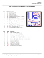
MV-55 and MV-55(B) have the following five simultaneous outputs:
•
Waveform Upright (pin 23)
•
Waveform Inverted (pin 24)
•
Tempo LED (pin 10)
Pin 10 will output a (0 - 3.1 volt) square wave that also reflects the duty cycle and will indicate the
offset amount.
The Tempo LED output is always pulsing, even if the chip is in Bypass mode. Further, in Clock
mode, the Tempo LED keeps pulsing even when no clock signal is being received.
Use a buffer if multiple circuits are driven off the Tempo LED.
•
Pin 14 - Synchronized Quarter-Note Pulse
Pin 14 will output synchronized quarter note (0 - 3.1 volt) pulses with a 50% duty cycle which are not
affected by the Duty Cycle, Offset, or Ratio controls.
In Pot/Tap mode, the pulses are continuously sent in time with the 1:1 ratio, quarter note interval.
In Pot/Tap mode, the pulses continue even if the chip is in Bypass mode. To synchronize the start
and stop of a sequencer circuit in Pot/Tap mode, connect Pin 18 via an inverter to the Clock Inhibit
pin of the 4017 Decade Counter chip rather than grounding that pin.
In Clock mode, the pulses are only sent when Clock data is being received and are synchronized to
the incoming Clock.
•
Pin 15 - Control Voltage (CV) Reset
To synchronize the reset of a sequencer circuit, connect Pin 15 to the Reset pin of the 4017 Decade
Counter chip.
In Pot/Tap mode, the CV Reset signal is sent upon the receipt of an initial Tap (i.e. the Tap Button
has not been pressed for at least 2.5 seconds). As such, a single tap can reset the sequencer.
In Clock mode, the CV Reset signal is sent after each MIDI Start command, whether or not Clock
information is being received.
[email protected]
PedalSync_MV-55_MV-55B_Tru-Foot_LFO_Datasheet.doc
© 2012 - MoltenVoltage.com - All Rights Reserved.
DRAFT v9.1