1
DMP248 Dewpoint
Transmitter
OPERATING
MANUAL
U263EN-1.4
MARCH 1999
PUBLISHED BY
VAISALA Oyj
P.O. Box 26
FIN-00421 Helsinki
FINLAND
Phone (int.): (+358 9) 894 91
Telefax:
(+358 9) 894 9227
Telex:
122832 vsala fi
Visit our internet pages at http://www.vaisala.com.
© Vaisala 1999
No part of this manual may be reproduced in any form or by any means,
electronic or mechanical (including photocopying), nor may its contents be
communicated to a third part without prior written permission of the copyright
holder.
The contents of instruction manuals are subject to change without prior notice.
_________________________________________________________________________CONTENTS
Table of contents
CHAPTER 1 GENERAL INFORMATION .......................................................................................................1
SAFETY ................................................................................................................................................................1
CHAPTER 2 PRODUCT DESCRIPTION .........................................................................................................3
GENERAL CHARACTERISTICS ...............................................................................................................................3
THE OPERATING PRINCIPLE OF THE DMP248 .......................................................................................................4
Use in high pressure .......................................................................................................................................6
CHAPTER 3 INSTALLATION ...........................................................................................................................7
SELECTING THE PLACE OF INSTALLATION ............................................................................................................7
MOUNTING THE TRANSMITTER ............................................................................................................................7
Mounting; overview .......................................................................................................................................9
Mounting the probe directly to the process ..................................................................................................10
Installing the probe through the ball valve assemply ...................................................................................11
Mounting the probe with a quick connect ....................................................................................................17
SAMPLE CELL .....................................................................................................................................................18
Optional installation by means of the sampling system DSS10 ...................................................................20
Grounding ....................................................................................................................................................21
Connections..................................................................................................................................................23
Connection to an AC supply ........................................................................................................................24
CHAPTER 4 COMMISSIONING .....................................................................................................................25
SECURITY LOCK JUMPER ....................................................................................................................................25
SELECTING THE ANALOGUE OUTPUTS ................................................................................................................26
CONNECTING THE RS 232C SERIAL BUS ............................................................................................................28
Reverting to factory settings of the serial port .............................................................................................30
CHAPTER 5 COMMANDS ...............................................................................................................................33
COMMANDS AND SECURITY LOCK JUMPERS .......................................................................................................33
LED COMMANDS ...............................................................................................................................................34
DISPLAY/KEYPAD COMMANDS ...........................................................................................................................35
Display mode ...............................................................................................................................................35
Command mode ...........................................................................................................................................35
Entering numbers .........................................................................................................................................35
Auto-calibration ...........................................................................................................................................36
Forced auto-calibration.................................................................................................................................38
Analogue output commands.........................................................................................................................38
Selecting the output (mA/V)..................................................................................................................................... 38
Selecting and scaling the analogue output quantities................................................................................................ 39
Output via serial bus.....................................................................................................................................40
Turning the serial interface echo oON/OFF ............................................................................................................. 40
Serial bus settings ..................................................................................................................................................... 40
Setting the transmitter address .................................................................................................................................. 42
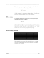
Selecting the output units.......................................................................................................................................... 42
Output modes ...............................................................................................................................................42
Setting the serial interface operation mode............................................................................................................... 43
Others ...........................................................................................................................................................44
Pressure compensation.............................................................................................................................................. 44
Setting the date ......................................................................................................................................................... 45
Setting the time......................................................................................................................................................... 45
VAISALA ___________________________________________________________________________I
OPERATING MANUAL _______________________________________________________________
SERIAL COMMANDS ........................................................................................................................................... 46
Auto-calibration........................................................................................................................................... 46
Pressure compensation ................................................................................................................................ 48
Analogue outputs......................................................................................................................................... 49
Setting the analogue outputs .....................................................................................................................................49
Selecting and scaling the analogue output quantities ................................................................................................49
Scaling the analogue outputs.....................................................................................................................................50
Output via the serial bus .............................................................................................................................. 50
Starting the measurement output...............................................................................................................................50
Stopping the measurement output .............................................................................................................................51
Outputting the reading once ......................................................................................................................................51
Setting the output interval for the RUN mode...........................................................................................................51
Serial bus settings......................................................................................................................................................52
Selecting the output units ..........................................................................................................................................52
Setting the transmitter address ..................................................................................................................................52
Resetting the transmitter............................................................................................................................................53
Operating the transmitter via the serial bus ................................................................................................. 53
Setting the serial interface .........................................................................................................................................53
OPEN & CLOSE ......................................................................................................................................................53
CHAPTER 6 CALIBRATION .......................................................................................................................... 55
HUMIDITY CALIBRATION ................................................................................................................................... 55
Two-point calibration procedure ................................................................................................................. 56
Using serial commands .............................................................................................................................................56
Using display/keypad commands..............................................................................................................................57
Using LED commands ..............................................................................................................................................57
Humidity calibration table ........................................................................................................................... 59
TEMPERATURE CALIBRATION ............................................................................................................................ 59
One point offset correction .......................................................................................................................... 59
Using serial commands .............................................................................................................................................59
Using display/keypad commands..............................................................................................................................60
Using LED commands ..............................................................................................................................................60
Two-point temperature calibration .............................................................................................................. 61
Using serial commands .............................................................................................................................................61
Using display/keypad commands..............................................................................................................................62
Using LED commands ..............................................................................................................................................62
CALIBRATION OF THE ANALOGUE OUTPUTS ...................................................................................................... 63
Using serial commands................................................................................................................................ 63
Using display/keypad commands ................................................................................................................ 63
Using LED commands................................................................................................................................. 64
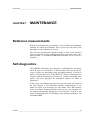
CHAPTER 7 MAINTENANCE ........................................................................................................................ 67
REFERENCE MEASUREMENTS ............................................................................................................................ 67
SELF-DIAGNOSTICS ........................................................................................................................................... 67
TEMPERATURE CHANNEL ADJUSTMENT WITH PT 100 SIMULATORS .................................................................. 68
Adjustment using serial commands ............................................................................................................. 69
Adjustment using display commands .......................................................................................................... 69
Adjustment using LED commands .............................................................................................................. 69
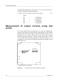
MEASUREMENT OF OUTPUT CURRENTS USING TEST POINTS............................................................................... 70
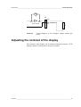
ADJUSTING THE CONTRAST OF THE DISPLAY ..................................................................................................... 71
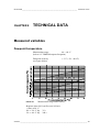
CHAPTER 8 TECHNICAL DATA .................................................................................................................. 73
MEASURED VARIABLES ..................................................................................................................................... 73
Dewpoint temperature ................................................................................................................................. 73
Temperature................................................................................................................................................. 74
Relative humidity ........................................................................................................................................ 74
Ppm volume concentration (dry) ................................................................................................................. 74
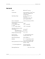
OUTPUTS ........................................................................................................................................................... 74
II _______________________________________________________________________
U263EN-1.4
_________________________________________________________________________CONTENTS
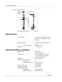
GENERAL ............................................................................................................................... ............................75
ELECTRONICS ....................................................................................................................................................76
SERIAL INTERFACE MODULES ............................................................................................................................76
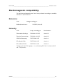
ELECTROMAGNETIC COMPATIBILITY .................................................................................................................77
Emissions .....................................................................................................................................................77
Immunity ......................................................................................................................................................77
CHAPTER 9 OPTIONS......................................................................................................................................78
CHAPTER 10 SPARE PARTS AND ACCESSORIES .................................................................................79
APPENDIX 1 SERIAL COMMANDS...............................................................................................................81
APPENDIX 2......................................................................................................................................................103
APPENDIX 3......................................................................................................................................................107
APPENDIX 4......................................................................................................................................................117
APPENDIX 5......................................................................................................................................................127
APPENDIX 6......................................................................................................................................................131
APPENDIX 7......................................................................................................................................................133
APPENDIX 8......................................................................................................................................................139
VAISALA __________________________________________________________________________ III
CHAPTER 1_______________________________________________________ GENERAL INFORMATION
CHAPTER 1
GENERAL INFORMATION
Safety
Throughout the manual important instructions regarding the safety
considerations are focused as follows.
WARNING Warning denotes a hazard. It calls attention to a procedure, practice,
condition or the like, which, if not correctly performed or adhered to,
could result in injury to or death of personnel.
CAUTION
Caution denotes a hazard. It calls attention to a procedure, practice,
condition or the like, which, if not correctly performed or adhered to,
could result in damage to or destruction of part or all of the product.
NOTE
Note highlights important information. It calls attention to an essential
procedure, practice, condition or the like.
Warranty
Vaisala issues a guarantee for the material and workmanship of this
product under normal operating conditions for one (1) year from the
date of delivery. Exceptional operating conditions, damage due to
careless handling and misapplication will void the guarantee.
VAISALA __________________________________________________________________________ 1
CHAPTER 2_______________________________________________________ PRODUCT DESCRIPTION
CHAPTER 2
PRODUCT DESCRIPTION
General characteristics
The DMP248 transmitter is a microprocessor-based instrument for the
measurement of dewpoint temperature in low humidities. The
transmitter measures other quantities as well: relative humidity,
temperature and ppm concentration (dry). When the dewpoint
temperature is below 0 °C, the transmitter calculates the frostpoint
instead of the dewpoint. The dewpoint output can be scaled freely, for
example, dewpoint -40...+20 °C can be set to correspond to 0...1 V.
The DMP248 transmitter has two analogue outputs and can be
connected to a serial bus via the RS 232C interface or optionally
through an RS 485/422 serial module or a current loop module.
The transmitter can be configured in many ways. It can have either a
blank cover or a cover with a local display and keypad with which the
user can operate the transmitter. The power supply voltage can be selected from three alternatives (24 VDC/VAC, 115 VAC, 230 VAC).
Two analogue output signals are selected from the measured
quantities; the signals can be scaled and the measurement ranges
changed within certain limits. The transmitter can be supplied with
two, five or ten metre sensor head cable. The alarm output option
enables two separate alarms that can be freely set by user.
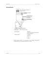
Options
Alarm output
Power supply
Serial interface
Display cover
Cable length
2 relays 8A/230V SPCO relays
24 VDC (VAC) (standard), 115/230 VAC
RS 232C (standard), RS 485/422, current loop
cover with or without local display & keypad
2, 5 or 10 metres
VAISALA __________________________________________________________________________ 3
OPERATING MANUAL _______________________________________________________________
The operating principle of the DMP248
The DMP248 transmitter incorporates the DRYCAP® sensor which is
optimized to be used in low humidities but has also an excellent
tolerance against condensation. The DRYCAP® sensor uses an
operating principle based on changes in capacitance as its thin
polymer film absorbs water molecules together with a combined
temperature measurement with a Pt 100 resistive temperature sensor.
The capacitance of the thin polymer film has a direct response
proportional to RH, but combined with the temperature signal the
response of the DRYCAP® sensor is rather proportional to Pw (water
vapour pressure) or to the dewpoint.
While frostpoints (dewpoints below 0 °C) in principle can be
determined by using traditional RH transmitters, it is very difficult
considering the required accuracy at the dry end calibration. As
relative humidity levels approach zero the accuracy rapidly decreases
and the offset soon becomes the largest source of errors when
monitoring frostpoints. Therefore, the focus is to minimize the offset
(error at 0% RH) when monitoring the process gas.
For example to monitor a process with a frostpoint of -40 C and a
temperature of +20 C translates to a relative humidity of 0.55%. An
offset error of -0.2 %RH, which is well within specifications for a
normal RH-transmitter, brings the measured RH down to 0.35%. This
would bring the calculated frostpoint down to -44 C. Thus seemingly
minor offset errors caused by drift or bad calibration translate into
unacceptable frostpoint errors when the RH is low.
To solve the accuracy problem the DMP248 transmitter utilizes a new
patented method that automatically adjusts the dry end measurement
in frostpoints. The offset calibration algorithm incorporated into the
DMP248 transmitter uses the fact that the capacitance of a thin film
polymer sensor is proportional to RH as seen in formula 1.
RHout = RH0 + Gain *
Pw
Pws( T )
(2-1)
where:
RH0=output in completely dry state
Pw=water vapor pressure
Pws(T)=temperature dependent water vapor saturation pressure
4 ______________________________________________________________________ U263EN-1.4
CHAPTER 2_______________________________________________________ PRODUCT DESCRIPTION
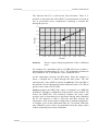
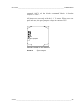
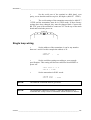
The function Pws(T) is well known from literature. Thus, it is
possible to determine the offset (RH 0) if measurements are made at
two or (preferably) more temperatures assuming a constant Pw
during the process.
0.4
0.3
20°C
RHout(%)
0.2
0.1
30°C
0
-0.1
-0.2
-0.3
0
0.005
0.01
0.015
0.02
0.025
0.03
0.035
0.04
0.045
1/Pws(T)
FIGURE 2-1
Device output during hypothetical offset calibration
cycle.
For example, for a transmitter with a -0.2%RH offset error is made 11
measurements at temperatures 20...30 °C. The frostpoint is assumed to
stay constant at -40 °C and that the 'Gain' is nominal 100%.
As the temperature increases the RH drops. Since the response is
linear, a straight line is fitted through the data points. The line
intercepts the y-axis at RH0 as shown in FIGURE 2-1. Now the RH0 is
known and it can be subtracted from the indicated value 0.35% RH to
get the correct value of 0.55% RH.
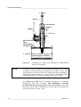
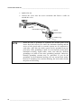
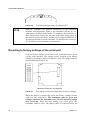
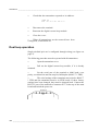
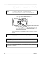
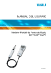
shows the DRYCAP sensor as mounted on a DMP248
probehead. Through a combination of the polymer sensor and Pt 100
sensor, the DRYCAP will accurately measure the water vapor
pressure used in determining low dewpoints. During auto-calibration
the Pt 100 element is used to first heat and then measure the
temperature of the sensor while cooling back to ambient temperature.
A complete cycle of auto-calibration takes 60...70 seconds. When the
auto-calibration cycle is active, the transmitter locks the output values
to those measured prior to auto-calibration.
FIGURE 2-2
VAISALA __________________________________________________________________________ 5
OPERATING MANUAL _______________________________________________________________
FIGURE 2-2
The DRYCAP sensor mounted on a DMP248 probe.
Note that the auto-calibration takes place only if the DMP248 is used
in ambient humidities below 10 %RH (dewpoint below -12 °C at 20 °
C) and at ambient temperature 0...+80 °C.
Use in high pressure
If the process pressure differs from the normal ambient pressure, the
value has to be entered in the transmitter memory to ensure the best
possible measurement accuracy. The pressure setting is used for
pressure compensation of the DMP248 transmitter. Note that although
dewpoint is a pressure dependent parameter, this setting cannot be
used for calculating dewpoints in different pressures. The probe
should be installed to a place with pressure equal to that of the process
in order to ensure the most reliable measurement. For converting
pressure units, see Appendix 8.
NOTE
The probe can be installed in the process through the ball valve
assembly provided that the process pressure is less than 10 bars. This
way, the process does not have to be shut down when installing or
removing the probe. However, if the probe is not removed from the
process as such (e.g. the process is shut down first), the process
pressure can be max. 20 bars.
6 ______________________________________________________________________ U263EN-1.4
CHAPTER 3_______________________________________________________________ INSTALLATION
CHAPTER 3
INSTALLATION
Selecting the place of installation
Select a place which gives a true picture of the environment or
process; also select a place that is as clean as possible. Air should
circulate freely around the sensor.
It is recommended that the sensor head is installed directly in the
process through the ball valve assembly. When the ball valve
assembly is used, the chamber or the duct does not have to be emptied
or shut down for installation or removal of the probe. Install the sensor
head transversely against the direction of the process flow.
If the probe head has to be installed aside of the process gas flow or
the process is very hot or particularly dirty, the probe can be installed
in a “leak-through” position. In this installation, the probe is mounted
behind the ball valve assembly and if necessary, a cooling coil and/or
a filter can be mounted in between. The flow passes through the
sensor head and leaks out through a vent hole in the fitting body
enabling a reasonable response time. In hot and dirty processes, a
sample system can also be used.
Mounting the transmitter
In FIGURE 3-1 and FIGURE 3-2, you can see the dimensions of the
DMP248 transmitter:
VAISALA __________________________________________________________________________ 7
OPERATING MANUAL _______________________________________________________________
104
120
CL
ENT
ø6.5
65
133
145
Dimensions of the DMP248 electronics housing (in
mm).
FIGURE 3-1
NOTE
1. Always mount the transmitter housing with the cable bushings
pointing downwards to ensure IP65 (NEMA4) rating
2. Make sure that the connection cable has the right thickness
(∅7...10 mm) and that the cable bushing is carefully tightened.
3. Pay always special attention to closing the transmitter cover
carefully and remember to tighten all four screws.
PROBE
PUSHED
DOWN
cable length
2, 5 or 10 m
ø5.5
PROBE UP
clasp nut
fitting body
non leaking screw (A)
(factory setting)
or leak screw (B)
(included in the package)
178
adjustment
range120 mm
149
31
29
R1/2 ISO 7/1
ø13.5
FIGURE 3-2
Probe dimensions (in mm).
8 ______________________________________________________________________ U263EN-1.4
CHAPTER 3_______________________________________________________________ INSTALLATION
NOTE
Take care not to damage the pipe of the probe. If the pipe is damaged,
the probe head is less tight and it will not go through the clasp nut.
Mounting; overview
fitting body
hex = 24mm
tapered thread
R1/2 ISO 7/1
parallel thread
G1/2 ISO 228/1
(BS 2779, JIS B0202)
ø19mm drilling
>10.5mm
>40mm
sealing with:
1. LOCTITE® No 542 + activ. No 7649 (t=-55...+150 °C)
2. MEGA-PIPE EXTRA No 7188 (t=-55...+170 °C)
3. PTFE tape (t=-60...+210 °C) NOTE: the tape does not lock
the parts together. Therefore, use two fork spanners (hex 24 and
27 mm) for tightening and opening the clasp nut of the probe
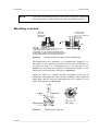
FIGURE 3-3
Process or pipe wall
Sealing and thread cutting for the fitting body.
The fitting body can be installed e.g. on standard pipe fittings (G 1/2
ISO 228/1) or on a thread in the process wall. If the wall thickness is
less than 10.5 mm, it is recommended to use a welded sleeve (see
FIGURE 3-3). Note that the minimum recommended distance of the
fitting body and probe head is 40 mm (see FIGURE 3-3).
probe
Adjust the probe to a suitable distance according to the type of
installation, and tighten the clasp nut first manually. Then, mark the
fitting body and the clasp nut and tighten the nut a further 50...60°
with a fork spanner (see FIGURE 3-4).
a pen
clasp nut
60° max.
fitting body
FIGURE 3-4
Tightening the clasp nut.
VAISALA __________________________________________________________________________ 9
OPERATING MANUAL _______________________________________________________________
NOTE
Be careful not to tighten the clasp nut more than 60° as this may
result in difficulties when trying to open it.
The probe is delivered with non-leaking screw A mounted. For bypass measurements, this screw is removed and replaced with leaking
screw B (included) and an O-ring is placed on the groove of the
sintered filter prior to installation. Make sure to tighten the screw
carefully.
Screw B has a small (0.08 mm) laser-made hole in the middle; the gas
or air to be measured passes through the sintered filter and by the
sensor, and leaks out through the screw.
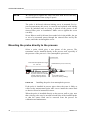
Mounting the probe directly to the process
Select a point, which gives a true picture of the process. The
transmitter can be installed directly in the process wall, especially if
the pressure of the process is 1 bar (atmospheric processes).
process wall
recommended adjustment range
25...135 mm
Leave at least 25 mm (1 ")
25 mm of probe head free to enable
a faster response time in
unpressurized processes
FIGURE 3-5
welded sleeve (G1/2, Ø 40 mm)
non leaking screw
(screw A, factory setting)
Installing the probe in an atmospheric process.
If the probe is installed in process pipes where the water is likely to
collect at the measurement point, take care to install the sensor head
so that it will not be immersed in water.
When the probe is installed directly on the process wall or pipe, note
that a closing valve may be needed on both sides of the installed probe
so that the sensor head can be removed from the process for
calibration and maintenance.
10 _____________________________________________________________________ U263EN-1.4
CHAPTER 3_______________________________________________________________ INSTALLATION
If the sensor head is installed in a pressurized chamber, always make
sure that the pressure of the chamber is equalized with the ambient
pressure prior to removing the probe.
capped nut
DIN 917-M22x1.5
when the probe is pulled
out for maintenance, cap
the hole with a capped nut;
this way, the process can be
open although the probe is
not in place
welded sleeve
(G1/2)
process pipe
FIGURE 3-6
sealing
Non leaking screw
(screw A)
closing valve
(ball valve)
Installing the sensor head directly on the process pipe.
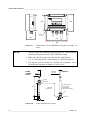
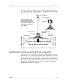
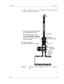
Installing the probe through the ball valve assembly
The best way to install the sensor head is through the ball valve
assembly. Use a 1/2” ball valve assembly with a ball hole of ∅14 mm
or more. In this kind of installation, it is not necessary to empty or
shut down the process for installing or removing the sensor head. If
the sensor head is installed in a process pipe, please note that the
nominal size of the pipe must be at least 1 inch. See FIGURE 3-7 FIGURE 3-8 for detailed instructions.
VAISALA _________________________________________________________________________ 11
OPERATING MANUAL _______________________________________________________________
probe
non-leaking
screw A
handle
>30 mm
ball of the ball
valve
(hole diameter
at least 14 mm)
process pipe / chamber
FIGURE 3-7
NOTE
Installing the sensor head through the DMP248BVS
ball valve assembly.
The probe can be installed in the process through the ball valve
assembly provided that the process pressure is less than 10 bars. This
way, the process does not have to be shut down when installing or
removing the probe. However, if the process is shut down before
removing the probe, the process pressure can be max. 20 bars.
See FIGURE 3-8- FIGURE 3-11 for detailed description of installation
through the ball valve assembly. This installation is possible
provided that the process pressure is less than 10 bars. Note also
that if the sensor head is installed in a process pipe, the nominal size
of the pipe must be at least 1 inch.
12 _____________________________________________________________________ U263EN-1.4
CHAPTER 3_______________________________________________________________ INSTALLATION
•
STEP 1: mount the probe with the ball valve assembly closed;
tighten the clasp nut manually.
bushing R1/2 cone/G1/2(40 bar)
e.g. Camozzi 2520-1/2-1/2
(the bushing serves for
moving the probe (sinter)
to such a distance from the
ball valve that the valve
can be closed)
ball valve 1/2" (40 bar)
e.g. Atlas Copco:BAL-1A 15 (G1/2)
clasp nut
fitting body
R1/2 cone, sealed
>30 mm
bushing
R1/2 cone
sealed
nipple
R1/2 cone
sealed
FIGURE 3-8
Installing the probe through the ball valve assembly;
step 1.
VAISALA _________________________________________________________________________ 13
OPERATING MANUAL _______________________________________________________________
STEP 2: open the ball valve assembly.
148 mm
manual
press
tool
adjustment range 120mm
•
probe pipe
ø5.5
marking groove
clasp nut
(hex 27 mm)
61
handle
fitting
ferrule
fitting body
(hex. 24 mm)
leak screw (B)
(hex. 1.5 mm)
ø14
15
29
(40)
ball of the
ball valve
O-ring
>
=
ø13.5
DRYCAP® sensor
filter
14
R1/2 ISO 7/1
FIGURE 3-9
Installing the probe through the ball valve assembly;
step 2 (measures in mm).
14 _____________________________________________________________________ U263EN-1.4
CHAPTER 3_______________________________________________________________ INSTALLATION
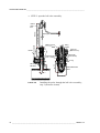
STEP 3: push the probe head through the ball valve assembly into the
process. If the pressure is high, use a manual press tool. Note that the
sensor head must be pushed so deep that the filter is completely inside
the process flow.
MANUAL
PRESS TOOL
VALVE OPEN
VALVE CLOSED
FILTER
FIGURE 3-10
Installing the probe through the ball valve assembly;
step 3.
For by-pass measurements, the probe is mounted behind the ball valve
assembly and non-leaking screw A on the fitting body is replaced with
leaking screw B and O-ring is placed on the groove of the sintered
filter. Screw B has a small (0.08 mm) laser-made hole in the middle;
the gas or air to be measured passes through the sintered filter and by
the sensor, and leaks out through the screw. The process pressure
reduces in the hole of the screw B. This installation is recommended if
the process flow rate is >20 m/s and there is over-pressure in the
process.
VAISALA _________________________________________________________________________ 15
OPERATING MANUAL _______________________________________________________________
gas escape channel:
use this position for
by-pass measurements
leak screw (B)
NOTE
keep the marking
groove in sight when
using leak screw (B)
O-ring
sintered
filter
DRYCAP® sensor
process pipe
or chamber
FIGURE 3-11
Installing the sensor head for by-pass measurements.
When pushing the probe head through the ball valve assembly, be
careful not to break the sintered filter. Open and close the ball valve
assembly with the marking groove always in sight. In by-pass
measurements, the clasp nut is tightened manually prior to pressing
the probe through the valve. When the probe has been pressed through
and the valve is open, the nut is tightened 50...60° with a fork spanner
(hexagon 27 mm).
16 _____________________________________________________________________ U263EN-1.4
CHAPTER 3_______________________________________________________________ INSTALLATION
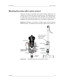
Mounting the probe with a quick connect
The probe can also be installed with a quick-connect, which acts as a
closing valve between the process and the probe. The installation can
be easily done even in small ducts with standard parts, and the probe
is easily removed when necessary. It is necessary for the probe to be
installed in the leak-through position for a reasonable response time.
illustrates an example of using a quick connect with the
DMP248 probe. The chamber can be made of stainless steel AISI 316.
FIGURE 3-12
keep the marking
groove in sight
when using
leak screw
15 mm
30 mm
leak screw
leak screw
G1/2
50 mm
chamber made of
hexagonal bar
(hex=27 mm)
G1/8
or G1/4
fitting part
of the quickconnect
process pipe
sealing
bayonet
socket
FIGURE 3-12
Installing the probe with a quick-connect.
VAISALA _________________________________________________________________________ 17
OPERATING MANUAL _______________________________________________________________
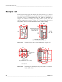
Sample cell
It may be necessary to use the sample cell if the process (e.g. a pipe) is
too small for the DMP248 sensor head. Furthermore, if the process is
very hot (>80 °C) or particularly dirty, the probe is installed in a
sample cell behind a cooling coil and/or filter. In this case, the
ambient temperature must be at least 10 °C warmer than the process
dewpoint in order to avoid condensation in the sample tubing.
6
40
28
6
PUSH PROBE
SINTER AGAINST
THIS EDGE,
TIGHTEN THE
CLASP NUT.
80
Sample gas inlet
use connector
R1/4 ISO 7/1
S
SAMPLE CELL
DMP248SC
G1/4
ISO
228/1
G1/2
ISO228/1
IN
view
A-A
68
OUT
G1/4
Sample gas outlet
use connector R1/4 ISO 7/1
FIGURE 3-13
Dimensions (in mm) of the DMP248SC sample cell.
25
20
22
for DMP248
probe
25
80
A
A
fixing screws
(e.g. M6x60 or 1/4" x 11/4")
40
TOP VIEW
FIGURE 3-14
SIDE VIEW
Fastening to a metal plate (top view) and on a concrete
frame (side view)
18 _____________________________________________________________________ U263EN-1.4
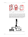
CHAPTER 3_______________________________________________________________ INSTALLATION
process
pipe
28
6
6
metal
plate
thickness e.g.
3mm (1/8")
AISI 316
SAMPLE CELL
DMP248SC
S
PUSH PROBE
SINTER AGAINST
THIS EDGE,
TIGHTEN THE
CLASP NUT.
G1/4
ISO
228/1
G1/4
screw
FRONT VIEW
FIGURE 3-15
68 80
thread M6 or
1/4"-20 UNC
metal
hose
clamp
40
TOP VIEW
Dimensions of the metal plate
Fastening to a process pipe with the help of a metal
plate
An overpressure in the process is necessary to create a flow through
the sample cell. Note that the pressure of the sample cell must not
differ from that of the process because dewpoint temperature changes
with pressure. In dirty processes, it may be necessary to use a filter
between the cooling coil and the sample cell. One more simple way of
using the sample cell with user provided accessories is shown in
FIGURE 3-16. The flow through the sample cell is controlled with the
needle valve and the pressure is kept equal to that of the process.
FIGURE 3-16
Installing the probe in high temperatures (an example).
VAISALA _________________________________________________________________________ 19
OPERATING MANUAL _______________________________________________________________
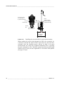
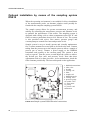
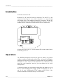
Optional installation by means of the sampling system
DSS10
When the operating environment is not suitable for direct installation
of the measurement probe, an alternate solution could possibly be
found with the complete sampling system DSS10.
The sample system allows for greater measurement accuracy and
stability by controlling the temperature, pressure and filtration levels
to optimize the performance of the sensor. The sampling system is
designed with cooling coils to reduce temperatures above 80 °C and
filters to remove particulate down to 0.01 micron of size. The system
is also provided with valves, flow meters, pressure gauges and
vacuum pumps to control flow rates and pressure levels.
Sample system is easy to install, operate and virtually maintenance
free. It comes mounted on a steel plate to be fixed to the wall. Connect
tubing from the process tap to the sample system to allow a sample of
process gas to travel. Connect a power supply to the DMP248
transmitter and possibly to the vacuum pump. The system is now
ready to operate. Turn the power on and adjust the values to achieve
the desired gas flow rates and pressure levels. Note that these
adjustments need to be done just once. As for maintenance, check the
filter elements periodically. The interval depends on the application.
1.
7.
2.
3.
5.
4.
6.
11.
9.
3.
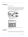
1. DMP248 transmitter
2. inlet valve
3. bracket
4. cooling coil
5. filter
6. sample cell
7. DMP248 probe
8. venting valve
9. pressure gauge
10. needle valve
11. flow meter
12. pump
13. power cord
connection
10.
12.
FIGURE 3-17
8.
13.
Sample system DSS10Electrical connections
20 _____________________________________________________________________ U263EN-1.4
CHAPTER 3_______________________________________________________________ INSTALLATION
Grounding
A single electrical cable with a screen and three to ten wires is
recommended for power and analogue output/serial bus connections.
The cable diameter should be 7...10 mm.
The screen of the electrical cable must be grounded properly to
achieve best possible EMC performance. Recommended cable shield
is done in the cable gland as shown.
•
remove the brass disks, rubber ring and nut from the transmitter
housing
•
strip 165 mm of the cable insulation, but leave 25 mm of the braid
visible
•
slip the nut and rubber ring over the cable insulation
•
slip the brass disk that has the bigger hole in it over the braid so
that it rests against the cable insulation
•
slip the other brass disk over the wires to the middle of the braid
flexible wires 0.5 mm²
(AWG 20), stranded wires
recommended
3
140
165
braid
shielding tube
brass
disks
braid
25
brass disks
rubber
ring
nut
D = Ø 7...10 mm
cable
(If the cable diameter is less
than 7mm, use a shrinking
tube or an adhesive tape)
•
push back the braid and press it between the two brass disks to
achieve a full 360° grounding; the fold between the disks should
have the same diameter as the brass disks
•
secure the braid with a shielding tube
•
insert the wires into the transmitter housing through the gland
VAISALA _________________________________________________________________________ 21
OPERATING MANUAL _______________________________________________________________
•
tighten the nut
•
connect the wires into the screw terminals and fasten a cable tie
around the wires
cable tie
transmitter housing
gland
brass disks
rubber ring
nut
NOTE
When the cable is grounded as explained, the metallic parts of the
sensor head, the screen of its cable, the transmitter housing and the
screen of the signal cable to external system are all connected to
each other. After this, the whole system can be grounded from one
point only. If the grounding is made via several points (sensor head,
transmitter housing, signal cable), make sure that the different
groundings are made to the same grounding potential. Otherwise,
harmful grounding currents may be generated. If you do the
grounding via the transmitter housing, use one serrated lock washer
between a mounting screw and the housing; the lock washer breaks
the paint on the housing.
22 _____________________________________________________________________ U263EN-1.4
CHAPTER 3_______________________________________________________________ INSTALLATION
CH1+
CH1 CH2 +
CH2 -
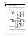
Connections
CH1- and CH2- are connected
together internally
+ V mA
CURRENT/VOLTAGE
OUTPUTS
+ V mA
24 V +
POWER SUPPLY
(INTERNAL OR
EXTERNAL)
Do not use power supply
ground (-) as output signal
ground
X2
X1
OPENED COVER OF THE DMP248
FIGURE 3-18
Power supply
Output signals
Electrical connections
24 VDC
24 VAC (see Chapter Connection
to an AC supply)
0...20 mA
4...20 mA
0...1 V
0...5 V
0...10 V
Power supply ground (-) is connected to the housing with parallel
connection of 15 nF capacitor and 300 kΩ resistor.
VAISALA _________________________________________________________________________ 23
OPERATING MANUAL _______________________________________________________________
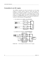
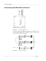
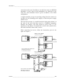
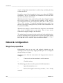
Connection to an AC supply
The DMP248 transmitter can also be connected to an AC supply
without an external rectifier. However, when more than one
transmitter is connected for example to one 24 VAC transformer, a
common loop is formed and there is an increased risk of a shortcircuit. To avoid this, always use separate floating supply for each
transmitter (see FIGURE 3-19A). However, if several transmitters have
to share one transformer, the phase (∼) must always be connected to +
connector in each transmitter (see FIGURE 3-19 B).
A) NO COMMON LOOP FORMED - RECOMMENDED
supply
voltage
signal
output
supply
voltage
signal
output
DMP248 transmitter
24 VAC
24 VAC
Controller
DMP248 transmitter
B) COMMON LOOP FORMED - NOT RECOMMENDED!
signal
output
Controller
shared
common
line
signal
output
supply
voltage
24 VAC
supply
voltage
DMP248 transmitter
DMP248 transmitter
FIGURE 3-19
Connecting the transmitter to an AC supply.
24 _____________________________________________________________________ U263EN-1.4
CHAPTER 4_____________________________________________________________ COMMISSIONING
CHAPTER 4
COMMISSIONING
When the DMP248 transmitter leaves the factory, its measurement
ranges and output signals have already been selected. The user can
subsequently change the measurement units between metric and nonmetric and select and scale the output signals with software functions,
see Chapter Selecting and scaling the analogue output quantities and
Appendix 1.
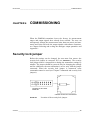
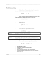
Security lock jumper
Before the settings can be changed, the user must first remove the
security lock jumper in connector X15 (see FIGURE 4-1). The security
lock jumper makes it impossible to change the transmitter settings by
mistake. The jumper should be removed only for changing the settings
and for calibration; the auto-calibration is active only with the jumper
connected. When the security lock jumper is connected, some
commands cannot be used (see Chapter Commands and security lock
jumpers).
X15
CHANGE OF SETTINGS
DISABLED
OPENED COVER OF THE DMP248
FIGURE 4-1
Location of the security lock jumper.
VAISALA _________________________________________________________________________ 25
OPERATING MANUAL _______________________________________________________________
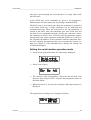
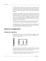
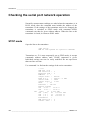
Selecting the analogue outputs
CH1
CH2
The DMP248 transmitter can be ordered ready with the current or
voltage outputs required. If the outputs need to be changed, move the
jumpers in connector X15 into positions as shown in FIGURE 4-2.
CH1 CH2
CH1
CH2
CURRENT OUTPUTS
0 ... 20 / 4 ... 20 mA
CH1 CH2
CH1
CH2
VOLTAGE OUTPUTS
0 ... 5 V / 0 ... 10 V
CH1 CH2
CH1
CH2
VOLTAGE OUTPUTS
0 ... 1 V
CH1 CH2
CH1 0 ... 1 VOLTAGE OUTPUT
CH2 CURRENT OUTPUT
X15
OPENED COVER OF THE DMP248
FIGURE 4-2
Selecting the analogue outputs with jumpers.
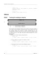
The software also has to be informed which outputs are in use. This is
done either through the serial interface or the menus on local display
when in use. The serial command is AMODE and the display/keypad
command 0RGHÕ$QDORJRXWSXWVÕ0RGH(see Chapter 5
commands). If the outputs need to be scaled, see serial
26 _____________________________________________________________________ U263EN-1.4
CHAPTER 4_____________________________________________________________ COMMISSIONING
command ASCL and the display command 0RGH Õ $QDORJ
RXWSXWVÕ6FDOH.
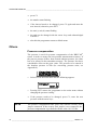
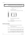
All jumpers are used only with the 0...1 V outputs. When other outputs are in use, the spare jumpers are kept in connector X55.
X55
spare jumpers
OPENED COVER OF THE DMP248
FIGURE 4-3
Spare jumpers
VAISALA _________________________________________________________________________ 27
OPERATING MANUAL _______________________________________________________________
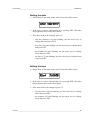
Connecting the RS 232C serial bus
RX
GND
TX
NC
X6
OPENED COVER OF THE DMP248
FIGURE 4-4
Serial bus connections.
To connect a PC to the DMP248 transmitters via the RS 232C serial
bus, one of the following cables is required. The type of cable depends
on the terminal and the connector type.
D9S
PC
2
5
3
4
6
7
8
3
7
2
D25S
5
6
8
20
TERMINAL
3
D25P 7
2
FIGURE 4-5
TXD
RXD
TXD
RXD
TXD
RXD
TX
GND
RX
TX
GND
RX
DMP248
TX
GND
RX
Connection of cables.
28 _____________________________________________________________________ U263EN-1.4
CHAPTER 4_____________________________________________________________ COMMISSIONING
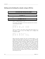
When the serial bus has been connected between the PC and the
transmitter, the PC is switched on. When using a PC, a terminal
emulation programme (e.g. Procomm Plus, Datastorm or Windows
terminal) is started.
The factory settings for data transfer are:
NOTE
•
4800 baud
•
even parity
•
7 data bits
•
1 stop bit
•
full duplex
When the serial bus settings are changed, the transmitter has to be
reset before the new settings become effective.
The processor does not allow the following combinations:
•
no parity, 7 data bits, 1 stop bit: if this combination is given the
DMP248 programme will change the number of stop bits to 2.
•
even or odd parity, 8 data bits, 2 stop bits: if this combination is
given the programme changes the number of stop bits to 1.
Refer to the manuals of the PC and the terminal emulation programme
when giving serial settings.
The RS 232C screw terminal cannot be used if an RS 485/422 serial
module or a current loop module is used. See Appendices 3 and 4 on
how to install and operate these modules.
In calibrating or changing the settings of the transmitter, it can be
more convenient to use the connector X17, if connector X6 is already
in use. This connector, however, transfers only RS 232C signals. If a
RS 485/422 serial port module or a current loop module has been
installed, it has to be removed before communicating through the X17
connector.
VAISALA _________________________________________________________________________ 29
OPERATING MANUAL _______________________________________________________________
RX GND TX
X17
FIGURE 4-6
NOTE
Location and connections of connector X17.
Some PC computers can generate interferences to the measured
humidity and temperature values if the transmitter and the PC are
connected to different mains outlets. To minimize the possibility of
these interferences, always use the same main outlet (same phase of
the main electricity) for the PC and the power supply of DMP248. It
is always preferable to use the connector X6 instead of the connector
X17 because it is more immune to interferences.
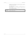
Reverting to factory settings of the serial port
If the serial port settings are not known, no commands can be given
via the serial interface. The settings can be reverted to the factory
settings by inserting a jumper in connector X16. The jumper must be
inserted when the power is on!
X16
OPENED COVER OF THE DMP248
FIGURE 4-7
Forcing the serial port settings back to factory settings.
When the jumper is inserted the serial line factory settings become
valid, but only temporarily. The transmitter must be given new
settings; otherwise, the transmitter uses the old, unknown settings
after power-up. When the new settings have been given, the
transmitter must be reset. The jumper must be removed before the
30 _____________________________________________________________________ U263EN-1.4
CHAPTER 4_____________________________________________________________ COMMISSIONING
transmitter is reset; if the jumper is in place when power is turned on,
the transmitter does not work.
After jumper insertion the transmitter is in STOP mode, ready to
receive commands.
The same method is used when the transmitter is in POLL mode and
the user has forgotten its address.
CAUTION
Inserting a jumper in any other place in connector X16 voids the
guarantee of the transmitter.
VAISALA _________________________________________________________________________ 31
CHAPTER 5________________________________________________________________ COMMANDS
CHAPTER 5
COMMANDS
The DMP248 transmitter uses a microprocessor; therefore, its
configuration can be set according to the user’s needs. This is done
through commands, either utilizing the menus on the local display or
giving commands through the serial interface (see Appendix 1). Most
often, the commands are used to change the settings of the two
analogue channels.
A limited range of commands can be given with the three press
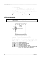
switches - up, down and enter - inside the transmitter housing. Four
LEDs indicate the command given with the up and down switches.
LED commands can be used to calibrate the transmitter (both
humidity and temperature) or to calibrate the analogue outputs.
A full range of commands can be given through the display/keypad or
through the RS 232C serial bus. The commands can be used e.g. to
select and scale the outputs, to calibrate the humidity and temperature
channels as well as the analogue outputs and to set the serial interface.
Commands and security lock jumpers
In order to prevent any tampering with the transmitter settings, the
transmitter cannot be calibrated, the analogue outputs set or the
analogue output quantities selected or scaled unless the security lock
jumper has been disconnected. The commands involved are:
•
all LED commands (except DCAL)
•
display/keypad commands:
&DOL
Õ
0RGH
Õ
5+7
$QDORJRXWSXWV
$QDORJRXWSXWV
Õ 0RGH
6FDOH
VAISALA _________________________________________________________________________ 33
OPERATING MANUAL _______________________________________________________________
•
serial commands:
CRH, CT, FCRH, ACAL; AMODE, ASEL, ASCL
In the following, the description of these functions is preceded with a
reminder of the security lock jumper:
Disconnect the security lock jumper!
LED commands
NOTE
If the transmitter has a display/keypad cover, the LED commands
cannot be used.
LEDs
UP
DOWN
press switches
ENT
OPENED COVER OF THE DMP248
FIGURE 5-1
Location of press switches and LEDs
Use the up and down switches (marked with arrows on the printed
board) to find the desired command code and acknowledge it with the
ENT switch. The command codes are (l = lit, = dark):
l
l
ll
ll
(0)
(1)
(2)
(3)
(9)
return to normal state
relative humidity calibration
temperature calibration
calibration of analogue outputs
forced auto-calibration (one auto-calibration; the
security lock jumper must be connected)
34 _____________________________________________________________________ U263EN-1.4
CHAPTER 5________________________________________________________________ COMMANDS
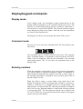
Display/keypad commands
Display mode
In the display mode, the transmitters output measurements on the
display; different quantities can be scrolled with the arrow keys. The
first line is scrolled with button σ and the second line with button τ;
all selections are stored with ENTER. The selected quantities appear
on the display also after power failure. After the reset, the transmitters
are always in the display mode.
The display also shows error messages and alarms if they occur.
Command mode
Press the CL key to enter the command mode. The first display is the
main menu:
The commands can be scrolled with the arrow keys. The currently
active command flashes; a command is selected with the ENT key.
When a menu is displayed, either the first command or the currently
valid setting flashes. The CL key takes the transmitter back to the
display mode.
Entering numbers
When the transmitter needs numbers to be entered into the programme
(e.g. when scaling or setting the analogue outputs, in calibration or
when giving the transmitter an address), the field is either empty or
the currently valid figure is displayed. Any previously given value is
deleted with the CL key.
When the field is empty, a cursor blinks at the right side of the
display. Pressing the arrow keys brings either a blank (), a comma (,),
a dash (-), a full stop (.) or a number from 0 to 9 on the display. The
right character is selected with ENT; after that, the number or numbers
move left one step. Entering numbers is ended with selecting a blank
() and pressing ENT. The last character entered can be deleted with
CL. If CL or ENT key is pressed when the field is empty, the program
returns to the previous display.
VAISALA _________________________________________________________________________ 35
OPERATING MANUAL _______________________________________________________________
With some commands (e.g. calibration) the figures are changed using
the arrow keys. When an arrow key is pressed continuously for a
while, the numbers start changing at an increasing rate.
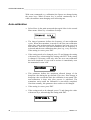
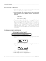
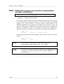
Auto-calibration
•
Select 0RUH in the main menu and then again 0RUH in the second
More menu. Select 'U\FDO and then 6HWWLQJV.
•
The interval parameter defines the frequency of auto-calibration
cycles. When the transmitter is turned on, the first auto-calibration
takes place after an hour unless the frequency has been set to less
than an hour. After the first auto-calibration, the set frequency is
activated and the auto-calibration takes place e.g. every six hours.
If the setting is correct, press ENT.
•
If the setting needs to be changed, press CL and change the setting
with arrow keys; acknowledge the setting with ENT. If the setting
is changed, it becomes valid only after the next auto-calibration
has been completed. If you wish to activate it immediately reset
the transmitter or turn it off.
•
This parameter defines the maximum allowed change of the
dewpoint value during the pre-defined G7GSWLPH. If the change in
dewpoint value exceeds the limit, the calibration is not started. The
auto-calibration is done only after process is stabilized. The
transmitter retries untill the calibration is succesfully complited.
Note that normally, this parameter does not have to be changed.
•
If the setting is correct, press ENT.
•
If the setting needs to be changed, press CL and change the value
with arrow keys; acknowledge the setting with ENT.
36 _____________________________________________________________________ U263EN-1.4
CHAPTER 5________________________________________________________________ COMMANDS
•
This parameter defines the measuring time of the change in
dewpoint prior to the auto-calibration (see the parameter 0D[
G7GS.
•
If the setting is correct, press ENT.
•
If the setting needs to be changed, press CL and change the value
with arrow keys. Acknowledge the setting with ENT.
•
This parameter defines the maximum correction (%RH) the
transmitter does during each auto-calibration cycle. If the
correction exeeds the limit, the calibration is ignored. Note that
normally, this parameter does not have to be changed.
•
If the setting is correct, press ENT.
•
If the setting needs to be changed, press CL and change the value
with arrow keys; acknowledge the setting with ENT.
•
This parameter defines the time the output values prior to the autocalibration are frozen after the calibration. The time is for sensor
temperature stabilization.
•
If the setting is correct, press ENT.
•
If the setting needs to be changed, press CL and change the value
with arrow keys; acknowledge the setting with ENT.
NOTE
Auto-calibration takes place only when the security lock jumper is
connected. During auto-calibration, the reading on the display is
frozen.
NOTE
If the process pressure differs from the normal ambient pressure, the
value has to be entered in the transmitter memory to ensure the best
possible measurement accuracy. The pressure setting is used for
pressure compensation of the DMP248 transmitter.
VAISALA _________________________________________________________________________ 37
OPERATING MANUAL _______________________________________________________________
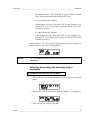
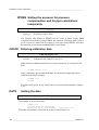
Forced auto-calibration
•
Select 0RUH in the main menu and then again 0RUH in the second
More menu. Select 'U\FDO and then &DOLEUDWLRQ
•
Select 0RUH in the main menu and then again 0RUH in the second
More menu. Select 'U\FDO and then &DOLEUDWLRQ. The following is
displayed:
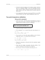
&DOLEUDWLRQ
SUHVVDQ\NH\WRDERUW
•
If you press any key, the calibration is interrupted. If no key is
pressed, the calibration takes place immediately. The text above is
displayed during the calibration. If the process is unstable (see
Chapter Auto-calibration) or relative humidity is over 10%, the
calibration is not performed. The text above is only shortly
displayed and the display returns to the measuring mode. The
calibration is not performed again even if the maximum correction
is exceeded.
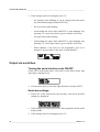
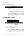
Analogue output commands
Selecting the output (mA/V)
Disconnect the security lock jumper!
•
Select 0RGH in the main menu and $QDORJRXWSXWV in the Mode
menu:
•
Select 0RGH P$ 9 . The current settings for channel 1 are
displayed:
•
If the settings are correct, press ENT.
•
If the settings need to be changed, press CL:
38 _____________________________________________________________________ U263EN-1.4
CHAPTER 5________________________________________________________________ COMMANDS
− the quantity (mA/V) starts flashing; it can be changed with the
arrow keys and acknowledged with the ENT key
− the lower limit starts flashing
− acknowledge the lower limit with ENT or start changing it by
pressing CL; a new lower limit is given one character at a time
with the arrow keys
− the upper limit starts flashing
− acknowledge the upper limit with ENT or start changing it by
pressing CL; a new upper limit is given one character at a time
with the arrow keys
When channel 1 has been set, the programme goes on to channel 2;
the procedure is the same as with channel 1.
NOTE
Also the analogue output jumpers must be set to correct places (see
FIGURE 4-2)
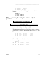
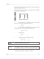
Selecting and scaling the analogue output
quantities
Disconnect the security lock jumper!
•
Select 0RGH in the main menu and $QDORJRXWSXWV in the Mode
menu:
•
Select 6FDOH. The quantity and scaling for channel 1 are displayed:
•
If the settings are correct, press ENT.
VAISALA _________________________________________________________________________ 39
OPERATING MANUAL _______________________________________________________________
•
If the settings need to be changed, press CL:
− the quantity starts flashing; it can be changed with the arrow
keys and acknowledged with the ENT key
− the lower limit starts flashing
− acknowledge the lower limit with ENT or start changing it by
pressing CL; a new lower limit is given with the arrow keys
− the upper limit starts flashing
− acknowledge the upper limit with ENT or start changing it by
pressing CL; a new upper limit is given with the arrow keys
− When channel 1 has been set, the programme goes on to
channel 2; the procedure is the same as with channel 1.
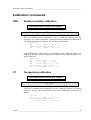
Output via serial bus
Turning the serial interface echo ON/OFF
Select 0RUH in the main menu, select 0RUH in the More menu, then
again 0RUH and then (FKR.
•
Use the arrow keys to select the right alternative and press ENT.
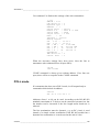
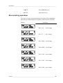
Serial bus settings
•
Select 6HUL in the main menu; the currently valid serial interface
settings are displayed:
•
If the settings are correct, press ENT; the programme returns to the
display mode.
•
If the settings need to be changed, press CL:
40 _____________________________________________________________________ U263EN-1.4
CHAPTER 5________________________________________________________________ COMMANDS
•
Select the parameter to be changed with the arrow keys and ENT
key.
Selecting baud rate:
Selecting parity:
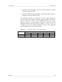
Selecting data bits:
Selecting stop bits:
Full duplex/half duplex:
The processor does not allow the following combinations:
NOTE
•
no parity, 7 data bits, 1 stop bit: if this combination is given the
DMP248 programme will change the number of stop bits to 2
•
even or odd parity, 8 data bits, 2 stop bits: if this combination is
given the programme changes the number of stop bits to 1
The serial bus settings become effective only after reset.
VAISALA _________________________________________________________________________ 41
OPERATING MANUAL _______________________________________________________________
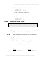
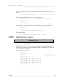
Setting the transmitter address
Address is used when more than one transmitter is connected to one
serial bus; it makes it possible to communicate with one transmitter at
a time.
•
Select 0RUH in the main menu and $GGU in the More menu; the
following is displayed:
•
Pressing ENT returns the programme to the main menu.
•
Pressing CL deletes the old address; enter the new address with
the arrow keys.
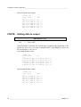
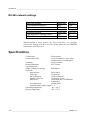
Selecting the output units
•
Select 8QLW in the main menu:
•
Use the arrow keys to select the right alternative and press ENT.
metric
RH
T
Td
ppmv
%RH
°C
°C
ppm
nonmetric
%RH
°F
°F
ppm
Output modes
The output modes only affect output through the serial interface: the
transmitter accepts all display and LED commands irrespective of
which serial output mode it is in. The DMP248 transmitter has three
serial output modes: RUN, STOP and POLL.
In the RUN state the transmitter outputs measurements automatically
through the serial interface to a PC or a peripheral. The only command
42 _____________________________________________________________________ U263EN-1.4
CHAPTER 5________________________________________________________________ COMMANDS
that can be given through the serial interface is S (stop) which ends
the RUN state.
In the STOP state serial commands are given to the transmitters.
Measurements are then output only by entering command SEND.
The POLL state is used when more than one transmitter is connected
to the same serial bus; a single transmitter can be addressed and
communicated with. When the connection to the one transmitter is
opened in the POLL state, the transmitter goes into STOP state and
can then receive commands normally. Closing the connection returns
the transmitter to POLL state. In POLL state the transmitter outputs
measurement only when requested (command SEND aa). If the user
has forgotten the address of the transmitter and the transmitter does
not have a display, the transmitter has to be reverted to the factory settings (see Chapter 0). If the transmitter has a display, the settings can
be checked through it.
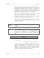
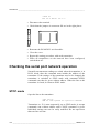
Setting the serial interface operation mode
•
Select 0RGH in the main menu; the following is displayed:
•
Select 6HULDORXWSXW:
•
The currently valid setting flashes. Select the desired mode with
the arrow keys and press ENT. After this the programme returns to
the Mode Menu.
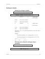
•
When Run mode is selected, the currently valid output interval is
displayed:
The output interval setting can be changed as follows:
VAISALA _________________________________________________________________________ 43
OPERATING MANUAL _______________________________________________________________
•
press CL
•
the number starts flashing
•
if the interval needs to be changed, press CL again and enter the
new interval; otherwise press ENT
•
the unit (s, min, h) starts flashing
•
the unit can be changed with the arrow keys and acknowledged
with ENT
•
after this the programme returns to Mode menu
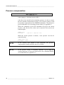
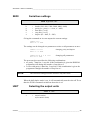
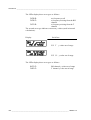
Others
Pressure compensation
The pressure is used for pressure compensation of the DRYCAP
sensor in order to ensure the best possible measurement accuracy. If
the process pressure differs from normal ambient pressure, the value
has to be entered in the transmitter memory. The pressure also has a
considerable effect on the ppmv value. The pressure to be entered is
the absolute pressure in hPa (for converting pressure units, see
Appendix 8).
NOTE
•
Select 3UHV in the main menu and the following appears:
•
Pressing ENT returns the programme to the main menu without
changing the pressure reading.
•
If the pressure needs to be changed, press CL; enter the new
pressure with the arrow keys
The pressure compensation takes place only with the security lock
jumper connected. If the security lock jumper is not connected, the
pressure compensation is performed with the value 1013.25 hPa.
44 _____________________________________________________________________ U263EN-1.4
CHAPTER 5________________________________________________________________ COMMANDS
Setting the date
•
Select 0RUH in the main menu; select 'DWH in the More menu:
•
If the date is correct, acknowledge it by pressing ENT; this takes
the programme back to the More menu.
•
If the date needs to be changed, press CL.
− first the centuries (19) start flashing; use the arrow keys to
change them and press ENT
− the years (92) start flashing; use the arrow keys to change them
and press ENT
− the months (06) start flashing; use the arrow keys to change
them and press ENT
− the days (17) start flashing; use the arrow keys to change them
and press ENT
Setting the time
•
Select 0RUH in the main menu; select 7LPH in the More menu:
•
If the time is correct, acknowledge it by pressing ENT; this takes
the programme back to the More menu.
•
If the time needs to be changed, press CL.
− first the hours (14) start flashing; use the arrow keys to change
them and press ENT
− the minutes (25) start flashing; use the arrow keys to change
them and press ENT
VAISALA _________________________________________________________________________ 45
OPERATING MANUAL _______________________________________________________________
− the seconds (32) start flashing; use the arrow keys to change
them and press ENT
NOTE
The transmitter does not have a real-time clock with backup battery.
This means that the date and time settings are not permanent.
Serial commands
More detailed descriptions of the serial commands can be found in
Appendix 1. Here only the most commonly used command sequences
are described. The instructions on how to connect the DMP248
transmitters to serial bus are given in Chapter Connecting the RS
232C serial bus.
Pressing ESC always interrupts any serial command being given. In
the commands <cr> means carriage return.
Auto-calibration
DRYCAL<cr>
>drycal
DCAL ON
Interval min : 360 ?
Max dTdp: 2.00 ?
dTdp time s : 10 ?
Max corr. : 0.040 ?
Settl time s : 50
>
The interval parameter defines the frequency of auto-calibration
cycles. When the transmitter is turned on, the first auto-calibration
takes place after on hour unless the frequency has been set to less than
an hour. After the first auto-calibration, the set frequency is activated
and the auto-calibration takes place e.g. every six hours. If the setting
is changed, it becomes valid only after the next auto-calibration has
been completed. If you wish to activate it immediately reset the
transmitter or turn it off.
46 _____________________________________________________________________ U263EN-1.4
CHAPTER 5________________________________________________________________ COMMANDS
The 0D[G7GS parameter defines the maximum allowed change of the
dewpoint value during the pre-defined G7GS time. If the change in
dewpoint value exceeds the limit, the calibration is not started. The
auto-calibration is done only after process is stabilized. The
transmitter retries untill the calibration is succesfully complited. Note
that normally, this parameter does not have to be changed.
The G7GSWLPH defines the measuring time of the change in dewpoint
prior to the auto-calibration (see the parameter 0D[G7GS.
The Max corr. parameter defines the maximum correction (%RH) the
transmitter does during each auto-calibration cycle.
The 6HWWO WLPH defines the time the output values prior to the autocalibration are frozen after the calibration. The time is for sensor
temperature stabilization.
NOTE
Normally, the Max dTdp and the Max corr. parameters need not be
changed.
NOTE
Auto-calibration takes place only when the security lock jumper is
connected. With command <fst on>, the serial line printing indicates
the stages of the auto-calibration (n = no auto-calibration, w,h,s =
different phases in auto-calibration, S = settling time auto-calibration
is on).
DCAL<cr>
>dcal
Calibration...
any key to abort
>
(appears when the auto-calibration
is completed in 60 - 70 seconds)
If you press any key, the calibration is interrupted. If no key is
pressed, the calibration takes place immediately. If the process is
unstable or relative humidity is over 10%, the prompt (>) appears
immediately. In that case the calibration is not performed. The
calibration is not performed again even if the maximum correction is
exceeded. (see Chapter Display/keypad commands)
VAISALA _________________________________________________________________________ 47
OPERATING MANUAL _______________________________________________________________
Pressure compensation
PRES pppp.pp <cr>
where pppp.pp = absolute pressure (hPa).
value has to be entered in the transmitter memory in order to ensure
the best possible measurement accuracy. The pressure setting is used
for pressure compensation of the DMP248 transmitter. The pressure is
given in hPa/mbar; for converting pressure units, see Appendix 8.
When the command is given, the transmitter first gives the current
pressure; after this the new value can be entered or the current one
acknowledged.
>PRES <cr>
Pressure :
1013.25 ? 1000.00 <cr>
When the current pressure is known, a new pressure can also be
entered directly:
>PRES 1010 <cr>
Pressure : 1010
NOTE
If the security lock jumper is not connected, the pressure
compensation is made with the value 1013.25 hPa.
NOTE
If the pressure setting is frequently adjusted, e.g. by using an
external barometer as a pressure input source, the command XPRES
is recommended (see Appendix 1).
48 _____________________________________________________________________ U263EN-1.4
CHAPTER 5________________________________________________________________ COMMANDS
Analogue outputs
Setting the analogue outputs
Disconnect the security lock jumper!
AMODE a bb.bbb cc.ccc d ee.eee ff.fff <cr>
a
= channel 1:
U
I
bb.bbb
= lower limit of channel 1
cc.ccc
= upper limit of channel 1
d
= channel 2:
= voltage output
= current output
U
= voltage output
I
= current output
ee.eee
= lower limit of channel 2
ff.fff
= upper limit of channel 2
The bb.bbb, cc.ccc, ee.eee and ff.fff parameters are entered in volts or
milliamperes.
Example:
lower limit of channel 1 is 0 V and upper limit 1 V (U 0 1)
lower limit of channel 2 is 2 V and upper limit 10 V(U 2 10)
>AMODE U 0 1 U 2 10 <cr>
Ch1 : 0.000 ...
1.000 V
Ch2 : 2.000 ... 10.000 V
Selecting and scaling the analogue output
quantities
Disconnect the security lock jumper!
ASEL xxx yyy <cr>
VAISALA _________________________________________________________________________ 49
OPERATING MANUAL _______________________________________________________________
xxx
=
channel 1’s quantity
yyy
=
channel 2’s quantity (RH, T, Td, ppm)
Example: dewpoint temperature selected on channel 1 and
temperature on channel 2
>ASEL
Ch1 (
Ch1 (
Ch2 (
Ch2 (
>
Td
Td
Td
T
T
T <cr>
) lo
) hi
) lo
) hi
-50.00
10.00
10.00
100.00
’C
’C
’C
’C
? -40<cr>
?
0<cr>
?
0<cr>
? 60<cr>
Scaling the analogue outputs
Disconnect the security lock jumper!
ASCL <cr>
Example: dewpoint is scaled in the range of -40...0 °C and temperature in the range of 0...+60 °C
>ASCL <cr>
Ch1 ( Td )
Ch1 ( Td )
Ch2 ( T )
Ch2 ( T )
>
lo
hi
lo
hi
-50.00
10.00
10.00
100.00
’C
’C
’C
’C
? -40<cr>
?
0<cr>
?
0<cr>
? 60<cr>
Output via the serial bus
Starting the measurement output
R <cr>
Starts output of measurements to the peripheral devices (RUN mode);
the only command that can be used is S (stop).
The output format can be changed with command FORM (see
Appendix 1).
50 _____________________________________________________________________ U263EN-1.4
CHAPTER 5________________________________________________________________ COMMANDS
Stopping the measurement output
S<cr>
Ends the RUN mode; after this command all other commands can be
used.
Outputting the reading once
SEND <cr>
in STOP mode
or
SEND aa <cr> in POLL state
aa
= address of the transmitter when more than one
transmitter is connected to a serial bus (0...99)
Output:
Td= -9.3 ’C PPM=
Td= -9.3 ’C PPM=
2733 T= 22.1 ’C RH= 10.4 %RH
2730 T= 22.1 ’C RH= 10.4 %RH
...
The output format can be changed with command FORM (see
Appendix 1).
Setting the output interval for the RUN mode
INTV xxx yyy <cr>
xxx
=
yyy
=
output interval (0...255)
0: no pause between outputs
unit (s, min or h)
Example: output interval is changed into 10 minutes
>INTV 10 min <cr>
Output intrv. : 10 min
VAISALA _________________________________________________________________________ 51
OPERATING MANUAL _______________________________________________________________
Serial bus settings
SERI b p d s x <cr>
b
p
d
s
x
=
=
=
=
=
bauds (300, 600, 1200, 2400, 4800, 9600)
parity (n = none, e = even, o = odd)
data bits (7 or 8)
stop bits (1 or 2)
duplex (H = half, F = full)
The settings can be changed one parameter at a time or all parameters
at once:
>SERI O <cr>
4800 O 7 1 HDX
changing parity only
>SERI 600 N 8 1 F <cr>
600 N 8 1 FDX
changing all parameters
The processor does not allow the following combinations:
• no parity, 7 data bits, 1 stop bit: if this combination is given the
DMP248 programme will change the number of stop bits to 2
• even or odd parity, 8 data bits, 2 stop bits: if this combination is
given the programme changes the number of stop bits to 1
NOTE
The serial bus settings become effective only after reset.
When the half-duplex mode is set, it will automatically turn the echo
off. Even then, the ECHO command can indicate that echo is on.
Selecting the output units
UNIT x <cr>
x
=
m(etric units) (°C)
n(on-metric units) (°F)
Setting the transmitter address
ADDR aa <cr>
aa
=
address (0...99)
Example: transmitter is given address 99
>ADDR <cr>
Address
: 2 ?
99 <cr>
52 _____________________________________________________________________ U263EN-1.4
CHAPTER 5________________________________________________________________ COMMANDS
Resetting the transmitter
RESET <cr>
Operating the transmitter via the serial bus
Setting the serial interface
SMODE xxxx<cr>
xxxx =
STOP, RUN or POLL
In STOP mode: measurements output only by command, all
commands can be used
In RUN mode: outputting automatically, only command S can be
used
In POLL mode: measurements output only with command SEND.
When in POLL state, the output state is changed as
follows:
OPEN aa <cr>
SMODE xxxx<cr>
aa
=
xxxx =
address of the transmitter
STOP, RUN or POLL
The OPEN command sets the bus temporarily in STOP state so that the
SMODE command can be given.
Example:
>SMODE STOP <cr>
Serial mode
: STOP
setting STOP state
OPEN & CLOSE
OPEN nn <cr>
nn = address of the transmitter (0...99)
CLOSE <cr>
In STOP mode: command OPEN has no effect, CLOSE sets the
transmitter in POLL mode
In POLL mode: command OPEN sets the transmitter temporarily in
STOP mode, command CLOSE returns the
instrument to POLL mode
VAISALA _________________________________________________________________________ 53
OPERATING MANUAL _______________________________________________________________
Example: relative humidity calibration is performed at transmitter
2 which is in POLL state
>OPEN 2 <cr>
>CRH <cr>
...
>CLOSE <cr>
opens the line to transmitter 2
calibration started
line closed
54 _____________________________________________________________________ U263EN-1.4
CHAPTER 6_______________________________________________________________ CALIBRATION
CHAPTER 6
CALIBRATION
The DMP248 transmitter has been fully calibrated at the factory so
there should be no immediate need for recalibration. The transmitter
should be calibrated only if there is reason to believe that the
adjustments have changed. The adjustments of the temperature
measurement channel and the analogue outputs are particularly stable
and in normal circumstances, there is no need to recalibrate them.
Humidity calibration should be performed at least once a year.
Humidity calibration
The DMP248 transmitter is calibrated against two accurate RH
references. The calibration can be performed by the end-user, or the
instrument can be sent to Vaisala or a Vaisala representative. A twopoint calibration can be performed with Vaisala’s HMK15 or
HMK13B Calibrator.
A Ø 13.5 adapter must be used when calibrating with the HMK13B
Calibrator. The adapter (part no. 16611) can be ordered from Vaisala
or Vaisala representatives.
Calibration can be performed by giving the commands using the press
switches inside the housing, through the serial bus (serial commands)
or through the menus on the local display (display/keypad
commands).
When LED commands are used and when the two analogue channels
do not output either relative humidity and/or temperature, relative
humidity is calibrated on channel 1 and temperature is calibrated on
channel 2. The calibration ranges are 0...100 %RH and -20...+80 °C.
When the transmitter is calibrated at two points, the points must be
either 50 %RH or 50 C apart from each other.
VAISALA _________________________________________________________________________ 55
OPERATING MANUAL _______________________________________________________________
NOTE
As relative humidity is a temperature dependent parameter, the probe
and the salt bath calibrator have to stabilize to the same temperature
for best accuracy.
Two-point calibration procedure
A two-point humidity calibration should be performed in stable
conditions using saturated salt solutions as references.
Using serial commands
•
Leave the calibrator and the transmitter for at least 4 hours in the
same space so that their temperatures have time to equalize.
Remove the filter cap on the transmitter.
Disconnect the security lock jumper
before turning the transmitter on!
•
Place the sensor head in the calibration hole of the LiCl bottle (dry
end reference) in the humidity calibrator.
•
Wait for 10 minutes.
•
Give command CRH <cr>, enter the first point value and press
<cr>.
>CRH <cr>
RH : xx.x
Ref1 ? yy.y <cr>
Press any key when ready...
•
If you want to see how the sensor stabilizes to the humidity in the
calibrator, enter c <cr> instead of the first reference:
RH : 11.9 Ref1 ?
RH : 11.5 Ref1 ?
RH : 11.5 Ref1 ?
Press any key when
c <cr>
c <cr>
11.3 <cr>
ready...
•
Place the sensor head in the calibration hole of the NaCl bottle
(wet end reference) in the humidity calibrator.
•
Wait for 10 minutes.
56 _____________________________________________________________________ U263EN-1.4
CHAPTER 6_______________________________________________________________ CALIBRATION
•
Press any key and enter the second point value and press <cr>.
RH
•
:
xx.x
Ref2 ?
yy.y <cr>
The stabilization of the sensor can be monitored here as well by
entering c <cr> instead of the reference value.
Using display/keypad commands
•
Leave the calibrator and the transmitter for at least 4 hours in the
same space so that their temperatures have time to equalize.
Remove the filter cap on the transmitter.
Disconnect the security lock jumper
before turning the transmitter on!
•
Place the sensor head in the calibration hole of the LiCl bottle (dry
end reference) in the humidity calibrator.
•
Select &DOL in the main menu and then 5+; select 1RW FKDQJHG
and then two-point calibration 5+ SRLQW FDO. Change the first
point reading with the arrow keys to correspond the reference
humidity and press ENT; pressing an arrow once changes the
reading by 0.05 %RH.
•
Place the sensor head in the calibration hole of the NaCl bottle
(wet end reference) in the humidity calibrator.
•
Wait for 10 minutes.
•
If necessary, change the second point reading with the arrow keys
and press ENT.
Using LED commands
•
Leave the calibrator and the transmitter for at least 4 hours in the
same space so that their temperatures have time to equalize.
Remove the filter cap on the transmitter.
Disconnect the security lock jumper
before turning the transmitter on!
VAISALA _________________________________________________________________________ 57
OPERATING MANUAL _______________________________________________________________
•
Place the sensor head in the calibration hole of the LiCl bottle (dry
end reference) in the humidity calibrator.
•
Connect an ammeter/voltmeter to the analogue outputs (connector
X2). Give command l. At the first calibration point the
LED on the left flashes; adjust the first point (offset) with the
arrow switches to the value given in the calibration table (Chapter
0) and press ENT switch.
•
Place the sensor head in the calibration hole of the NaCl bottle
(wet end reference) in the humidity calibrator.
•
Wait for 10 minutes.
•
Check that the reading corresponds within the desired accuracy to
that given in the calibration table (Chapter 0). If not, adjust the
second point with the arrow switches to the correct value and press
ENT. At the second calibration point the second LED from the left
flashes.
58 _____________________________________________________________________ U263EN-1.4
CHAPTER 6_______________________________________________________________ CALIBRATION
Humidity calibration table
TABLE 6-1
Temperature
LiCl
4...20 mA
0...20 mA
0...1 V
0...5 V
0...10 V
NaCl
4...20 mA
0...20 mA
0...1 V
0...5 V
0...10 V
Greenspan’s calibration table
°C
°F
%RH
15
59
*
20
68
11.3
5.81
2.26
0.113
0.565
1.13
25
77
11.3
5.81
2.26
0.113
0.565
1.13
30
86
11.3
5.81
2.26
0.113
0.565
1.13
35
95
11.3
5.81
2.26
0.113
0.565
1.13
%RH
75.6
16.10
15.12
0.756
3.780
7.56
75.5
16.08
15.10
0.755
3.775
7.55
75.3
16.05
15.06
0.753
3.765
7.53
75.1
16.02
15.02
0.751
3.755
7.51
74.9
15.98
14.98
0.749
3.745
7.49
*) If the LiCl solution is used or stored in temperature below +18 °C (+64 °F), the
equilibrium humidity of the salt solution changes permanently.
Temperature calibration
The temperature channel has been calibrated at the factory and since it
is very stable, adjustment should be made only when there is strong
reason to believe that the adjustments have changed.
Temperature calibration should be performed against some accurate
temperature reference. It can be done either using the press switches
inside the housing, through the serial bus or the menus on the local
display. Either a one point offset correction or a two point calibration
is possible.
One point offset correction
Using serial commands
•
Leave the reference instrument and the transmitter for at least 4
hours in the same space so that their temperatures have time to
equalize. Remove the filter cap prior to calibration.
Disconnect the security lock jumper
before turning the transmitter on!
VAISALA _________________________________________________________________________ 59
OPERATING MANUAL _______________________________________________________________
•
Check the transmitter against the reference.
•
Give command CT <cr>, enter the first point value and press <cr>:
>CT <cr>
T : xx.x
Ref1 ? yy.y <cr>
Press any key when ready
•
If you want to see how the sensor stabilizes to the reference
temperature, enter c <cr> instead of the first reference:
T : 0.90 Ref1 ? c <cr>
T : 0.55 Ref1 ? c <cr>
T : 0.55 Ref1 ? 0.0 <cr>
Press any key when ready...
•
After giving the correct temperature value (Ref1) and pressing
<cr> press any key and then <cr>.
Using display/keypad commands
•
Leave the reference instrument and the transmitter for at least 4
hours in the same space so that their temperatures have time to
equalize. Remove the filter cap prior to calibration.
Disconnect the security lock jumper
before turning the transmitter on!
•
Check the transmitter against the reference.
•
Select &DOL in the main menu and then 7; select one-point
calibration 7SRLQWFDO.
•
Change the reading with the arrow keys to correspond to the
reference and press ENT.
Using LED commands
•
Leave the reference instrument and the transmitter for at least 4
hours in the same space so that their temperatures have time to
equalize. Remove the filter cap prior to calibration.
Disconnect the security lock jumper
before turning the transmitter on!
•
Check the transmitter against the reference.
60 _____________________________________________________________________ U263EN-1.4
CHAPTER 6_______________________________________________________________ CALIBRATION
•
Connect an ammeter/voltmeter to the analogue outputs (connector
X2). Give command l. At the first calibration point the
LED on the left flashes; adjust the first point (offset) with the
arrow switches to the same reading with the reference and press
ENT switch.
•
After adjusting the offset point and pressing ENT the second LED
from left flashes. Press ENT without changing the output value.
Two-point temperature calibration
Using serial commands
•
Leave the reference instrument and the transmitter for at least 4
hours in the same space so that their temperatures have time to
equalize. Remove the filter cap prior to calibration.
Disconnect the security lock jumper
before turning the transmitter on!
•
Check the transmitter against the reference.
•
Give command CT <cr>, enter the first point value and press <cr>:
>CT <cr>
T : xx.x
Ref1 ? yy.y <cr>
Press any key when ready
•
If you want to see how the sensor stabilizes to the reference
temperature, enter c <cr> instead of the first reference:
T : 0.90 Ref1 ? c <cr>
T : 0.55 Ref1 ? c <cr>
T : 0.55 Ref1 ? 0.0 <cr>
Press any key when ready...
•
Change the temperature and again check the transmitter against
the reference.
•
Check that the reading corresponds with the reading of the
reference instrument. If not, adjust the second point.
•
Press any key, enter the second point value and press <cr>.
T
:
xx.x
Ref2 ?
yy.y <cr>
VAISALA _________________________________________________________________________ 61
OPERATING MANUAL _______________________________________________________________
•
The stabilization of the sensor can be monitored well by entering c
<cr> instead of the reference value.
Using display/keypad commands
•
Leave the reference instrument and the transmitter for at least 4
hours in the same space so that their temperatures have time to
equalize. Remove the filter cap prior to calibration.
Disconnect the security lock jumper
before turning the transmitter on!
•
Check the transmitter against the reference.
•
Select &DOL in the main menu and then 7; select two-point
calibration 7SRLQWFDO. Change the first point reading with the
arrow keys and press ENT.
•
Change the temperature and again check the transmitter against
the reference.
•
Check that the reading corresponds with the reading of the
reference instrument. If not, adjust the second point.
•
If necessary, change the second point reading with the arrow keys
and press ENT.
Using LED commands
•
Leave the reference instrument and the transmitter for at least 4
hours in the same space so that their temperatures have time to
equalize. Remove the filter cap prior to calibration.
Disconnect the security lock jumper
before turning the transmitter on!
•
Check the transmitter against the reference.
•
Connect an ammeter/voltmeter to the analogue outputs (connector
X2). Give command l. At the first calibration point the
LED on the left flashes; adjust the first point (offset) with the
arrow switches to the same reading with the reference and press
ENT switch.
•
Change the temperature and again check the transmitter against
the reference.
62 _____________________________________________________________________ U263EN-1.4
CHAPTER 6_______________________________________________________________ CALIBRATION
•
Check that the reading corresponds with the reading of the
reference instrument. If not, adjust the second point.
•
If necessary, adjust with the arrow switches to the correct value
and press ENT. At the second calibration point the second LED
from the left flashes.
Calibration of the analogue outputs
The analogue outputs have been calibrated at the factory and since
they are very stable, calibration of the outputs should be performed
only when there is reason to believe that their adjustments have
changed.
Using serial commands
Disconnect the security lock jumper!
ACAL <cr>
The outputs on channels 1 and 2 are measured and the measured
values (mA or V) entered as calibration coefficients.
Example: both channels have 0...10 V outputs (set with AMODE
command); enter the voltages measured at the analogue outputs:
>ACAL <cr>
Ch1 U1 ( V
Ch1 U2 ( V
Ch2 U1 ( V
Ch2 U2 ( V
)
)
)
)
?
?
?
?
0.123 <cr>
9.98 <cr>
0.120 <cr>
9.98 <cr>
Using display/keypad commands
Disconnect the security lock jumper!
•
Connect an ammeter/voltmeter to the output of channel 1, select
&DOL in the main menu and $QDORJRXWSXWV in the Cali menu. The
following is displayed (the quantity can be either mA or V):
VAISALA _________________________________________________________________________ 63
OPERATING MANUAL _______________________________________________________________
•
Enter the measured lower end current/voltage on channel 1.
•
Enter the measured upper end current/voltage on channel 1.
•
Connect the meter to the output of channel 2 and enter the
measured lower end current/voltage on channel 2.
•
Enter the measured upper end current/voltage on channel 2.
Using LED commands
If both the analogue outputs and humidity/temperature channels are
calibrated, the analogue outputs should be calibrated first. This applies
only when the calibrations are done using the LED commands!
•
connect an ammeter/voltmeter to the analogue outputs (connector
X2)
Disconnect the security lock jumper!
•
Give command ll.
•
the LED on the left flashes; set the low end of channel 1 with the
arrow keys and press ENT
•
the second LED from the left flashes; set the high end of channel 1
with the arrow keys and press ENT
64 _____________________________________________________________________ U263EN-1.4
CHAPTER 6_______________________________________________________________ CALIBRATION
•
the LED on the left flashes; set the low end of channel 2 with the
arrow keys and press ENT
•
the second LED from the left flashes; set the high end of channel 2
with the arrow keys and press ENT
The analogue outputs are calibrated to ensure that outputs are
correctly scaled: for example, when the output is scaled to 4...20 mA,
the low end of the scale is 4 mA and high end 20 mA exactly.
However, when 0... 20 mA output is used, the output can not be
adjusted to exactly 0 mA, but to 50 µA. When 0...1 V, 0...5 V or 0...10
V output is in use, the output is adjusted to 50 mV. The following
table summarizes the correct output values.
TABLE 6-2
low end:
high end:
Summary of the correct output values
Output scale:
0...20 mA 4...20 mA
50 µA
4 mA
20 mA
20 mA
0...1 V
50 mV
1V
0...5 V
50 mV
5V
0...10 V
50 mV
10 V
VAISALA _________________________________________________________________________ 65
CHAPTER 7____________________________________________________________ MAINTENANCE
CHAPTER 7
MAINTENANCE
Reference measurements
Reference measurements are needed to verify whether the transmitter
readings are within specifications. This way the user can check if the
transmitter needs calibration or service.
The reference measurement should be made as close to the checked
sensor as possible and the readings should be read at the same time,
when possible. A re-calibrated DMP248 transmitter can be used as a
reference.
Self-diagnostics
The DMP248 transmitter goes through a self-diagnostics procedure
when the power is switched on. If the procedure does not reveal any
errors or faults, the transmitter starts operating normally. If errors or
faults are found, check first if the DRYCAP sensor is damaged. If it
is intact, send the transmitter to Vaisala or a Vaisala representative for
repairs. The error messages the transmitter outputs are listed in
Appendix 5.
If any errors occur during operation, the error messages are output on
the local display if the transmitter displays measurements; if the
menus are used, error messages are not output. The LEDs indicate
errors at all times. During operation, however, the error messages are
not output automatically through the serial interface. If there is any
reason to doubt that there is something wrong with the transmitter, use
command ERRS:
VAISALA _________________________________________________________________________ 67
OPERATING MANUAL _______________________________________________________________
ERRS <cr>
If there are no error messages, only a prompt is displayed:
>ERRS <cr>
>
When errors have occurred, the transmitter outputs the error code (see
Appendix 5 for all error messages):
>ERRS <cr>
E40 f ( all )
>
out of range
Temperature channel adjustment with Pt 100
simulators
Switch the power off and disconnect the wires to the Pt 100 sensor
from solder lugs TP5, TP6 and TP7.
TP6
TP7
X88
TP5
FIGURE 7-1
Location of solder lugs TP5, TP6 and TP7 and
connector X88
Connect a Pt 100 simulator to connector X88 and set it at the lowest
temperature to be calibrated.
Pt 100
X88
FIGURE 7-2
Connecting the Pt 100 simulator to connector X88
Switch the power on.
68 _____________________________________________________________________ U263EN-1.4
CHAPTER 7____________________________________________________________ MAINTENANCE
Adjustment using serial commands
Give command CT and enter the first point value and press <cr>:
>CT <cr>
’C : xx.x
Ref1 ? yy.y <cr>
Press any key when ready
Set the Pt 100 simulator at the highest temperature to be calibrated,
and press any key. Enter the second point (gain) reference reading. If
second reference is not needed, press <cr> to complete one point
offset correction.
Adjustment using display commands
Select &DOL in the main menu and then 7; select two-point calibration 7
SRLQW FDO. Change the first point reading with the arrow keys and
press ENT.
Set the Pt 100 simulator at the highest temperature to be calibrated,
and adjust the second point (gain) to the reference reading.
Adjustment using LED commands
Connect an ammeter/voltmeter to the analogue outputs (connector
X2). Give command l, and adjust the first point (offset) with
the arrow switches to the same reading with the reference and press
ENT switch.
Set the Pt 100 simulator at the highest temperature to be calibrated,
and adjust the second point (gain) to the reference reading. If there is
no second reference, press ENT to complete one point offset
correction.
Disconnect the Pt 100 simulator and reconnect the Pt 100 wires to
solder lugs TP5, TP6 and TP7.
The correct connections according to the wire colours are:
TP5
blue
TP6
green
TP7
yellow
TP8
black
If there is not a Pt 100 simulator available, the adjustment can be
made with two resistors of 84 Ω and 154 Ω whose resistance is known
precisely. Measure the resistor with a resistance meter. Look up the
VAISALA _________________________________________________________________________ 69
OPERATING MANUAL _______________________________________________________________
corresponding temperature value from a Pt 100 conversion table or
calculate it using the following equation:
T = D0 + R x {D1 + R x [D2 + R x (D3 + R x D4)]}
(7-1)
where
D0
D1
D2
D3
D4
=
=
=
=
=
-243.5673014
2.278542701
0.002050681
-6.15025E-06
1.34949E-08
Measurement of output currents using test
points
X15
CH1 +
+
CH2-
CH2+
CH1-
CH1+
If a current output has been connected e.g. to a process computer, the
output current cannot be measured at the output connector X2 without
disconnecting the external load. The output current can, however, be
measured at test points CH1+/CH1- and CH2+/CH2- without
disconnecting the output wires. These test points can therefore be used
in one point offset correction against an accurate reference or in
checking the current output without disconnecting the analogue output
from the process.
X2
CH2
OPENED COVER OF THE DMP248
FIGURE 7-3
Location of the CH1 and CH2 test points
70 _____________________________________________________________________ U263EN-1.4
CHAPTER 7____________________________________________________________ MAINTENANCE
mA
X2
CH1+
CH1CH1+
TEST POINTS
FIGURE 7-4
CH1-
RL
Circuit diagram of the analogue output current test
points
Adjusting the contrast of the display
The contrast of the display can be adjusted using the trimmer "LCD
display contrast" located next to the press switches.
VAISALA _________________________________________________________________________ 71
CHAPTER 8____________________________________________________________ TECHNICAL DATA
CHAPTER 8
TECHNICAL DATA
Measured variables
Dewpoint temperature
Measurement range
-60...+80 °C
(below 0 °C DMP248 outputs frostpoint)
Dewpoint accuracy
(see figure below)
FIGURE 8-1
± 2 °C (-50...+80 °C)
Measurement range and accuracy.
Response time (90%) at flow rate 0.08 m/s
(1 bar) at 20 °C:
-40 → -20 °C dp 35 s
-20 → -40 °C dp 240 s
VAISALA _________________________________________________________________________ 73
OPERATING MANUAL _______________________________________________________________
Temperature
Measurement range
for specified Td accuracy
-40...+80 °C
0...+80 °C
Typical accuracy of electronics
at +20 °C (+68 °F)
±0.1 °C
Typical temperature dependence of
electronics
0.005 °C/°C
Temperature sensor
Pt 100 IEC 751 1/3 Class B
Relative humidity
Measurement range
Accuracy at 20 °C
RH< 10 %RH
RH> 10 %RH
0...100 %RH
± 0.025 %RH + 8.75% of reading
± 0.7 %RH + 2% of reading
Ppm volume concentration (dry)
Typical measurement range
0...5000 ppmv
Accuracy at 20 °C, 1013.25 mbar
7.3 ppmv + 8.3% of reading
Outputs
Two analogue outputs selectable
0...20 mA 4...20 mA
0...1 V
0...5 V
0...10 V
Typical accuracy of an analogue
output at +20 °C
±0.05 % full scale
Typical temperature dependence
of an analogue output
0.005 %/°C full scale
Serial outputs
RS 232C
RS 485 (option)
current loop (option)
74 _____________________________________________________________________ U263EN-1.4
CHAPTER 8____________________________________________________________ TECHNICAL DATA
General
Sensor
DRYCAP S sensor
Connections
screw terminals, 0.5 mm2 wires
(AWG 20), stranded wires
recommended
Operating voltage
24 VDC/ isolated VAC
(20...28 V)
115 VAC/230 VAC with
power supply module
Power consumption
100 mA maximum (24 VDC)
Recommended external load for
current outputs
<500 Ω
0...1 V voltage output
>2 kΩ (to ground)
0...5 and
0...10 V voltage outputs
>10 kΩ (to ground)
Operating temperature range
(electronics)
-40...+60 °C
with display cover
0...+50 °C
with power supply unit -40...+45 °C
Storage temperature range
-40...+70 °C
Pressure range
Housing material
0 ...20 bar absolute pressure
G-AlSi12 (DIN 1725)
Housing classification
IP 65 (NEMA 4)
Bushing
for 7...10 mm diameter cable
(8 x 0.5 mm2 shielded cable)
Sensor protection (∅13.5 mm) stainless steel sintered filter
(part no. 16452)
for vacuum applications
Housing dimensions
stainless steel filter
(part no. HM46999 )
145 x 120 x 65 mm
VAISALA _________________________________________________________________________ 75
OPERATING MANUAL _______________________________________________________________
Sensor head dimensions:
PROBE
PUSHED
DOWN
PROBE UP
ø5.5
cable length
2, 5 or 10 m
adjustment
range120 mm
R1/2
ISO 7/1
178
29
31
R1/2 ISO 7/1
ø13.5
Weight of display cover
420 g
User interface
3 keys and 4 LEDs inside the
housing or local display keypad
(option)
Display (option)
2 x 16 character alphanumeric
LCD
3.85 mm (0.15")
1 x 4 keypad
Electronics
character height
Keyboard
Serial interface modules
Module types
Connections
Assembly
Number of devices on line
RS 485/422
digital current loop
Network cable type
Network line length
Network data speed
RS 485/422
digital current loop
RS 485/422
digital current loop
screw terminals for 0.5 mm2
wires (AWG 20), stranded
wires recommended
plug-in module
32
6 (single loop)
9 (dual loop)
twisted pair
1000 m max.
9600 baud max.
4800 baud max.
76 _____________________________________________________________________ U263EN-1.4
CHAPTER 8____________________________________________________________ TECHNICAL DATA
Electromagnetic compatibility
The emission and immunity tests have been performed according to standards
EN50081-1 and EN50082-2.
Emissions
Test:
Setup according to:
Radiated interference
EN55022 (class B)
Immunity
Test:
Setup according to:
Performance:
Electrostatic discharge
EN61000-4-2:1995
criteria B
Electrical fast transients
EN61000-4-4:1995
criteria B
GSM field immunity
ENV50204:1995
criteria A
RF radiated fields
ENV50140:1993
criteria A
RF conducted fields
ENV50141:1993
criteria A
Voltage proof, AC: DC supply (+ or -) to housing 250 VAC, 1 minute (300 kΩ
and 15 nF parallel)
VAISALA _________________________________________________________________________ 77
OPERATING MANUAL _______________________________________________________________
CHAPTER 9
OPTIONS
Power supply
24 VDC (VAC)(standard),
115/230 VAC
Serial interface
RS 232C (standard), RS 485/422,
current loop
Cable length
2, 5 or 10 metres
Alarm output
2 relays 8 A/ 230 V SPCO (Single Pole
Change Over) for adjustable low and
high alarm
Display cover
cover with or without local display & keypad
78 _____________________________________________________________________ U263EN-1.4
CHAPTER 10_______________________________________________ SPARE PARTS AND ACCESSORIES
CHAPTER 10
SPARE PARTS AND
ACCESSORIES
Order code
16452
DRYCAP S
HMP230PW
5237
HMP230RS
HMP230CL
DMP240ALSP
17143
HMP248SC
DSS10
DMP248BVS
16611
Description
Sintered filter, stainless steel
DRYCAP® S dewpoint sensor
Power supply module
Fuse 160 mA T 5x20 mm for power supply module
RS 485/422 serial module
Current loop module
Alarm output unit
Fuse 8 A for alarm output unit
Sample cell
Sample system
Ball valve set
Calibration adapter for the HMK13B Calibrator
VAISALA _________________________________________________________________________ 79
APPENDIX 1 SERIAL COMMANDS __________________________________________________________
APPENDIX 1 SERIAL COMMANDS
APPENDIX 1
AUTO-CALIBRATION COMMANDS
DRYCAL Defining the frequency of auto-calibration cycles
DCAL Forced auto-calibration
ANALOGUE OUTPUT COMMANDS
AMODE Setting the analogue outputs
ASEL Selecting the scaling the analogue output quantities
ASCL Scaling the analogue outputs
CALIBRATION COMMANDS
CRH
Relative humidity calibration
CT Temperature calibration
ACAL Calibrating the analogue outputs
L
Outputting linear correction coefficients
LI
Entering linear correction coefficients
OUTPUT VIA THE SERIAL BUS
R
Starting the measurement output
S Stopping the measurement output
SEND Outputting a reading once
DSEND Outputting readings of all connected transmitters once
ERRS Outputting error messages
ECHO Turning the serial interface echo ON/OFF
INTV Setting the output interval for the RUN state
FORM Setting the output format
FTIME
Adding time to output
FDATE
Adding date to output
SERI
Serial bus settings
UNIT Selecting the output units
ADDR Setting the transmitter address
RESET
Resetting the transmitter
OPERATION MODES
SMODE Setting the serial interface
OPEN & CLOSE
OTHERS
ITEST Testing the analogue outputs
PRES Setting the pressure for pressure compensation and ppm calculations
XPRES
Setting the pressure for pressure compensation and for ppm calculations temporarily
CDATE Entering calibration date
DATE Setting the date
TIME Setting the time
VERS Name and version of the programme
? Outputting the transmitter settings
??
Outputting the transmitter settings also in POLL mode
Setting and activating the outputs with menu commands
Setting and activating the outputs using an RS line
81
83
83
84
84
84
85
86
87
87
87
88
88
89
89
89
90
90
90
91
91
91
92
93
94
95
95
96
96
97
97
97
98
98
99
100
100
100
101
101
101
102
135
136
The commands function as described when the serial interface is in full-duplex mode
and echo is on. All commands except FORM can be given in either capital or small
letters.
In the commands <cr> means carriage return, <lf> line feed and <ht> horizontal
tabulation.
VAISALA _________________________________________________________________________ 81
APPENDIX 1 SERIAL COMMANDS __________________________________________________________
Auto-calibration commands
DRYCAL Defining the frequency of auto-calibration cycles
DRYCAL<cr>
>drycal
DCAL ON
Interval min : 360 ?
Max dTdp: 2.00 ?
dTdp time s : 10
Max corr. : 0.040 ?
The interval parameter defines the frequency of auto-calibration
cycles. When the transmitter is turned on, the first auto-calibration
takes place after on hour unless the frequency has been set to less than
an hour. After the first auto-calibration, the set frequency is activated
and the auto-calibration takes place e.g. every six hours. If the setting
is changed, it becomes valid only after the next auto-calibration has
been completed. If you wish to activate it immediately, reset the
transmitter or turn it off.
The 0D[G7GS parameter defines the maximum allowed change of the
dewpoint value during the pre-defined G7GS time before autocalibration. If the change in dewpoint value exceeds the limit, the
calibration is not started. The auto-calibration is done only after
process is stabilized. The G7GS defines the time for 0D[ G7GS
measurement.
The Max corr. parameter defines the maximum correction (%RH) the
transmitter does during each auto-calibration cycle. The 6HWWO WLPH
defines the time the output values (measured before auto-calibration)
are frozen after the auto-calibration. The time is for sensor
temperature stabilization.
NOTE
Normally, the Max dTdp and the Max corr. parameters need not be
changed.
NOTE
Auto-calibration takes place only when the security lock jumper is
connected.
VAISALA _________________________________________________________________________ 83
APPENDIX 1 SERIAL COMMANDS __________________________________________________________
DCAL
Forced auto-calibration
DCAL<cr>
>dcal
Calibration...
any key to abort
>
(appears when the auto-calibration
is completed, max. 60 - 70 seconds)
If you press any key, the calibration is interrupted. If no key is
pressed, the calibration takes place immediately. The text above is
displayed during the calibration. If the process is unstable (see
Chapter ) or relative humidity is over 10%, the calibration is not
performed. The text above is only shortly displayed and the display
returns to the measuring mode. The calibration is not performed again
even if the maximum correction is exceeded.
Analogue output commands
AMODE Setting the analogue outputs
Disconnect the security lock jumper!
AMODE a bb.bbb cc.ccc d ee.eee ff.fff <cr>
a
=
bb.bbb =
cc.ccc =
d
=
ee.eee =
ff.fff
=
channel 1:
U = voltage output
I = current output
lower limit of channel 1
upper limit of channel 1
channel 2:
U = voltage output
I = current output
lower limit of channel 2
upper limit of channel 2
The bb.bbb, cc.ccc, ee.eee and ff.fff parameters are entered in volts or
milliamperes.
Sets the analogue outputs on channels 1 and 2. An example of this is
when the voltage output on channel 1 is set to be 0...1 V and channel 2
set to 2...10 V:
84 _____________________________________________________________________ U263EN-1.4
APPENDIX 1 SERIAL COMMANDS __________________________________________________________
>AMODE U 0 1 U 2 10 <cr>
Ch1 : 0.000 ...
1.000 V
Ch2 : 2.000 ... 10.000 V
The current settings can be checked by giving the command without any
parameters:
>AMODE <cr>
Ch1 : 0.000 ... 20.000 mA
Ch2 : 0.000 ... 20.000 mA
ASEL
Selecting the scaling the analogue output
quantities
Disconnect the security lock jumper!
ASEL xxx yyy <cr>
xxx
yyy
=
=
channel 1’s quantity (Td, ppm, RH, T)
channel 2’s quantity (Td, ppm, RH, T)
For example, dewpoint temperature is selected to be output on channel 1
and temperature on channel 2; the temperature range is scaled to 0...60 °
C:
>ASEL
Ch1 (
Ch1 (
Ch2 (
Ch2 (
>
Td
Td
Td
T
T
T <cr>
) lo
) hi
) lo
) hi
-50.00
10.00
10.00
100.00
’C
’C
’C
’C
? -40<cr>
?
0<cr>
?
0<cr>
? 60<cr>
When the ASEL command is given on its own, the transmitter outputs
its current settings:
Ch1
Ch1
Ch2
Ch2
>ASEL <cr>
( Td ) lo
( Td ) hi
( T ) lo
( T ) hi
-50.00
10.00
10.00
100.00
’C
’C
’C
’C
?
?
?
?
<cr>
<cr>
<cr>
<cr>
VAISALA _________________________________________________________________________ 85
APPENDIX 1 SERIAL COMMANDS __________________________________________________________
The outputs and their scales can also be given directly with the ASEL
command.
ASEL xxx yyy aaa.a bbb.b ccc.c ddd.d <cr>
xxx
yyy
aaa.a
bbb.b
ccc.c
ddd.d
ASCL
=
=
=
=
=
=
channel 1’s quantity
channel 2’s quantity
lower limit of channel 1
upper limit of channel 1
lower limit of channel 2
upper limit of channel 2
Scaling the analogue outputs
Disconnect the security lock jumper!
ASCL <cr>
Scales the outputs selected on channels 1 and 2.
For example, scaling dewpoint temperature on the range of -40...0 °C
and temperature 0...+60 °C:
>ASCL <cr>
Ch1 ( Td )
Ch1 ( Td )
Ch2 ( T )
Ch2 ( T )
>
lo
hi
lo
hi
-50.00
10.00
10.00
100.00
’C
’C
’C
’C
? -40<cr>
?
0<cr>
?
0<cr>
? 60<cr>
The output scales can also be given directly with the ASCL command.
ASCL aaa.a bbb.b ccc.c ddd.d <cr>
aaa.a
bbb.b
ccc.c
ddd.d
=
=
=
=
lower limit of channel 1
upper limit of channel 1
lower limit of channel 2
upper limit of channel 2
For example, when dewpoint temperature is scaled to -40...0 °C on
channel 1 and temperature to 0...+60 °C on channel 2:
>ASCL -40
Ch1 ( Td
Ch1 ( Td
Ch2 ( T
Ch2 ( T
>
0
)
)
)
)
0
lo
hi
lo
hi
60 <cr>
-40.00 ’C
0.00 ’C
0.00 ’C
60.00 ’C
?
?
?
?
<cr>
<cr>
<cr>
<cr>
86 _____________________________________________________________________ U263EN-1.4
APPENDIX 1 SERIAL COMMANDS __________________________________________________________
Calibration commands
CRH
Relative humidity calibration
Disconnect the security lock jumper!
CRH <cr>
With this command the transmitters can be calibrated against two RH
references. Two-point calibration is performed using saturated salt solutions in
controlled conditions according to the following instructions:
>CRH <cr>
RH : 12.00
Ref1 ? 11.3 <cr>
Press any key when ready ...
RH : 76.00
Ref2 ? 75.5 <cr>
If the stabilization of the sensor to the humidity in the calibrator needs to be
monitored, the measurement output can be repeated by giving command c<cr>
at Ref1 and Ref2:
>CRH <cr>
RH : 12.00
RH : 11.70
RH : 11.50
Press any key
RH : 76.00
CT
Ref1
Ref1
Ref1
when
Ref2
? c <cr>
? c <cr>
? 11.3 <cr>
ready ...
? 75.5 <cr>
Temperature calibration
Disconnect the security lock jumper!
CT <cr>
Using this command the transmitters can be calibrated against an accurate
reference, such as a Pt 100 simulator. A two-point calibration is performed as
follows:
>CT <cr>
T : 0.80
Ref1 ?
0.0 <cr>
Press any key when ready ...
T : 56.20
Ref2 ?
55.0 <cr>
VAISALA _________________________________________________________________________ 87
APPENDIX 1 SERIAL COMMANDS __________________________________________________________
In one-point offset correction, the Ref2 prompt is acknowledged with <cr>:
>CT <cr>
T : 0.80
Ref1 ?
0.0 <cr>
Press any key when ready ...
T : 75.50
Ref2 ?
<cr>
If the stabilization of the sensor to the temperature of the calibrator or the reference needs to be monitored, the measurement output can be repeated by giving command c<cr> at Ref1 and Ref2:
>CT <cr>
T : 0.80
T : 0.40
Press any key
T : 56.20
ACAL
Ref1
Ref1
when
Ref2
?
c <cr>
?
0.00 <cr>
ready ...
?
55.0 <cr>
Calibrating the analogue outputs
Disconnect the security lock jumper!
ACAL <cr>
Calibrates the outputs selected on channels 1 and 2. The output is measured
and the measured values (mA or V) entered as calibration coefficients.
For example, calibrating the outputs when 0...10 V signal has been selected on
both channels (set with AMODE command)
>ACAL <cr>
Ch1 U1
(V
Ch1 U2
(V
Ch2 U1
(V
Ch2 U2
(V
L
)
)
)
)
?
?
?
?
0.123 <cr>
9.98 <cr>
0.120 <cr>
9.98 <cr>
Outputting linear correction coefficients
L <cr>
Calibration coefficients can be checked with command L.
>L <cr>
RH
offset
RH
gain
Ts
offset
Ts
gain
:
:
:
:
0.000
1.000
0.000
1.000
88 _____________________________________________________________________ U263EN-1.4
APPENDIX 1 SERIAL COMMANDS __________________________________________________________
LI
Entering linear correction coefficients
Disconnect the security lock jumper!
LI <cr>
The LI command is one way of calibrating the transmitters.
>LI
RH
RH
Ts
Ts
<cr>
offset
gain
offset
gain
:
:
:
:
0.000
1.000
0.000
1.000
? -.6 <cr>
? <cr>
? <cr>
? .4 <cr>
The factory settings are offset 0 and gain 1.
NOTE
The temperature unit in offset correction is always degrees
Centigrade, even if the transmitter is using non-metric units
(Fahrenheit) in its measurement output.
Output via the serial bus
R
Starting the measurement output
R <cr>
Starts output of measurements to the peripheral devices (PC display or printer);
output interval is set with command INTV.
Factory setting of the output format:
Td= -9.3 ’C PPM=
Td= -9.3 ’C PPM=
...
2733 T= 22.1 ’C RH= 10.4 %RH
2730 T= 22.1 ’C RH= 10.4 %RH
When the transmitter sends out the readings, the serial interface does not echo
any commands; the only command that can be used is S (stop).
The output format can be changed with command FORM.
VAISALA _________________________________________________________________________ 89
APPENDIX 1 SERIAL COMMANDS __________________________________________________________
S
Stopping the measurement output
S<cr>
Ends the RUN state; after this command all other commands can be used.
SEND
Outputting a reading once
SEND <cr>
in STOP state
or
SEND aa <cr> in POLL state
aa
=
address of the transmitter when more than one transmitter is
connected to a serial bus (0...99; set with command ADDR)
Outputs the current measurement readings via the serial line. The output type is
the following:
Td= -9.3 ’C PPM=
Td= -9.3 ’C PPM=
...
2733 T= 22.1 ’C RH= 10.4 %RH
2730 T= 22.1 ’C RH= 10.4 %RH
The output format can be changed with command FORM.
DSEND
once
Outputting readings of all connected transmitters
DSEND <cr>
All transmitters connected to the serial bus send their addresses and current
measurement readings in an order defined by their addresses. After receiving
DSEND command a transmitter sets a delay time according to its address value
and sends the data after this delay. DSEND works also in POLL mode. With
this command, the user can for example easily find out the addresses of the
transmitters.
The output when four transmitters with addresses 4, 5, 10, 33 have been connected to the serial bus:
>dsend <cr>
4
14.43 %RH
5
22.7 ’C
10
14.99 %RH
33
22.3 ’C
>
90 _____________________________________________________________________ U263EN-1.4
APPENDIX 1 SERIAL COMMANDS __________________________________________________________
ERRS
Outputting error messages
ERRS <cr>
During operation error messages are not output automatically through the serial interface. If there is any reason to doubt that there is something wrong with
the transmitter, possible error messages can be output with command ERRS.
If there are no error messages, only a prompt is displayed:
>ERRS <cr>
>
If errors have occurred, the transmitter outputs the error code (see Appendix 5
for error messages):
>ERRS <cr>
E40 f ( all )
>
ECHO
out of range
Turning the serial interface echo ON/OFF
ECHO xxx <cr>
xxx
=
ON or OFF
When the echo is off, the commands given through the serial interface or the
prompt > cannot be seen on the display.
When the serial interface is in half-duplex mode, the echo is always off. Even
then the ECHO command can indicate that echo is on.
INTV
Setting the output interval for the RUN state
INTV xxx yyy <cr>
xxx =
yyy =
output interval (0...255)
0: no pause between outputs
unit (s, min or h)
Sets the output interval when the transmitter outputs
measurement readings to a peripheral device.
For example, the currently valid settings are output with:
>INTV <cr>
Output intrv. :
0 min
VAISALA _________________________________________________________________________ 91
APPENDIX 1 SERIAL COMMANDS __________________________________________________________
When this is changed into 10 minutes, the command is:
>INTV 10 <cr>
Output intrv. :
10 min
The unit is changed into seconds with:
>INTV S <cr>
Output intrv. :
10 s
The change can also be done with one command:
>INTV 10 S <cr>
Output intrv. :
FORM
10 s
Setting the output format
FORM <cr>
"xxx...xxx"
? zzz...zzz <cr>
xxx...xxx
zzz...zzz
=
=
old format
new format
The FORM command sets the format of the outputs generated in RUN state
and by SEND command.
NOTE
Please note that capital and small letters have different meanings.
\DD..DD\
\TT..TT\
\UU..UU\
\MM..MM\
\PP..PP\
\uu..uu\
\n
\r
\t
\\
dewpoint temperature
temperature
relative humidity
ppm concentration
absolute pressure (hPa) (manually feeded value)
unit according to the preceding variable
line feed <lf>
carriage return <cr>
horizontal tabulation <ht> or <tab>
\
For example:
format
\UUU.UU\ \+TT.TT\\r
\TTT.T\ \uu\\r\n
\UUU.U\ \uuu\\+DD.D\ \uu\\r
output
100.00 +99.99 <cr>
15.2 ’C <cr><lf>
46.9 %RH +10.8 ’C <cr>
92 _____________________________________________________________________ U263EN-1.4
APPENDIX 1 SERIAL COMMANDS __________________________________________________________
Any text can be written in the command and it appears in the output. For example:
RH: \UUU.U\ T: \+TT.TT\\r
RH: 54.0
T: +25 <cr>
The format can be deleted by giving \ as a parameter:
Note. only one space before \ and none after
>FORM \<cr>
or
>FORM <cr>
"xxx...xxx"
?\<cr>
An example of a format suitable for use in Microsoft Excel spreadsheets:
>FORM <cr>
"xxx...xxx"
?\UUU.U\\t\TTT.T\\t\DDD.D\\t\\r\n <cr>
The output is then:
47.4<tab> 22.4 <tab> 10.6 <tab> <cr><lf>
FTIME
Adding time to output
FTIME xxx <cr>
xxx
=
ON or OFF
When FTIME is activated, the current time is output at the beginning of the
output line. The time is set with command TIME. After RESET or power on
the current time is 00:00:00.
Activating the time output
>ftime on
Form. time
: ON
>intv 5 s
Output intrv. :
5
>r
09:31:13 RH= 19.4 %RH
09:31:18 RH= 19.4 %RH
09:31:23 RH= 19.8 %RH
09:31:28 RH= 19.6 %RH
09:31:33 RH= 19.5 %RH
09:31:38 RH= 19.5 %RH
...
setting the output interval
s
T=
T=
T=
T=
T=
T=
26.0
26.0
26.0
26.0
26.0
26.0
’C
’C
’C
’C
’C
’C
VAISALA _________________________________________________________________________ 93
APPENDIX 1 SERIAL COMMANDS __________________________________________________________
Inactivating the time output
>ftime off
Form. time
>r
RH= 19.4 %RH
RH= 19.8 %RH
RH= 20.6 %RH
RH= 20.5 %RH
RH= 19.9 %RH
RH= 19.6 %RH
...
FDATE
:
OFF
T=
T=
T=
T=
T=
T=
26.1
26.1
26.1
26.1
26.1
26.1
’C
’C
’C
’C
’C
’C
Adding date to output
FDATE xxx <cr>
xxx
=
ON or OFF
When FDATE is activated, the current date is output at the beginning of the
output line. The date is set with command DATE. After RESET or power on
the current date is 1991-01-01.
Activating the date output
>fdate on
Form. date
>r
1995-03-10
1995-03-10
1995-03-10
1995-03-10
1995-03-10
...
:
RH=
RH=
RH=
RH=
RH=
ON
21.1
21.3
23.1
22.2
20.6
%RH
%RH
%RH
%RH
%RH
T=
T=
T=
T=
T=
26.0
26.0
26.0
26.0
26.0
’C
’C
’C
’C
’C
Inactivating the date output
>fdate off
Form. date
>r
RH= 20.2 %RH
RH= 19.9 %RH
RH= 19.8 %RH
RH= 19.7 %RH
RH= 19.7 %RH
...
:
OFF
T=
T=
T=
T=
T=
26.0
26.0
26.0
26.0
26.0
’C
’C
’C
’C
’C
94 _____________________________________________________________________ U263EN-1.4
APPENDIX 1 SERIAL COMMANDS __________________________________________________________
SERI
Serial bus settings
SERI b p d s x <cr>
b
p
d
s
x
=
=
=
=
=
bauds (300, 600, 1200, 2400, 4800, 9600)
parity (n = none, e = even, o = odd)
data bits (7 or 8)
stop bits (1 or 2)
duplex (H = half, F = full)
Giving the command on its own outputs the current settings:
>SERI <cr>
4800 E 7 1 FDX
The settings can be changed one parameter at a time or all parameters at once:
>SERI O H <cr>
4800 O 7 1 HDX
changing parity and duplex
>SERI 600 N 8 1 F <cr>
600 N 8 1 FDX
changing all parameters
The processor does not allow the following combinations:
• no parity, 7 data bits, 1 stop bit: if this combination is given the DMP248
programme will change the number of stop bits to 2
• even or odd parity, 8 data bits, 2 stop bits: if this combination is given the
programme changes the number of stop bits to 1
The serial bus settings become effective only after reset.
NOTE
When the half-duplex mode is set, it will automatically turn the echo off. Even
then the ECHO command can indicate that echo is on.
UNIT
Selecting the output units
UNIT x <cr>
x
=
m(etric units)
n(on-metric units)
VAISALA _________________________________________________________________________ 95
APPENDIX 1 SERIAL COMMANDS __________________________________________________________
Td
T
RH
metric units
°C
°C
%RH
non-metric units
°F
°F
%RH
For example, the command for setting the non-metric units is:
>UNIT N <cr>
Output units : non metric
When the command is given with no parameters, the transmitter outputs the
currently valid setting.
ADDR
Setting the transmitter address
ADDR aa <cr>
aa
=
address (0...99)
The address is used when more than one transmitter is connected to one serial
bus. The ADDR command makes it possible to communicate with one
transmitter at a time in POLL state.
For example, transmitter is given address 99
>ADDR <cr>
Address
:
2 ?
99 <cr>
When asking the current address, no address number is given:
>ADDR <cr>
Address
RESET
:
2 ? <cr>
Resetting the transmitter
RESET <cr>
Resets the transmitter. All settings that have been changed stay in the memory
even after reset or power failure.
96 _____________________________________________________________________ U263EN-1.4
APPENDIX 1 SERIAL COMMANDS __________________________________________________________
Operation modes
SMODE Setting the serial interface
SMODE xxxx<cr>
xxxx
=
STOP, RUN or POLL
In STOP mode: measurements output only by command, all commands can
be used
In RUN mode: outputting automatically, only command S can be used
In POLL mode: measurements output only with command SEND. When in
POLL mode, the output state is changed as follows:
OPEN aa <cr>
SMODE xxxx<cr>
aa
xxxx
=
=
address of the transmitter
STOP, RUN or POLL
The OPEN command sets the bus temporarily in STOP MODE so that the
SMODE command can be given. For example:
>SMODE
Serial
>SMODE
Serial
<cr>
mode
: STOP
STOP <cr>
mode
: STOP
which mode is in use at the moment
setting STOP mode
OPEN & CLOSE
OPEN nn <cr>
nn
=
address of the transmitter (0...99)
CLOSE <cr>
In STOP mode: command OPEN has no effect, CLOSE sets the transmitter in
POLL mode
In POLL mode: command OPEN sets the transmitter temporarily in STOP
mode, command CLOSE returns the instrument to POLL
mode
When more than one transmitter is connected to the same serial bus, the POLL
mode makes it possible to communicate with the transmitters. For example, a
relative humidity calibration is performed at transmitter 2 (<bel> = ASCII 7):
VAISALA _________________________________________________________________________ 97
APPENDIX 1 SERIAL COMMANDS __________________________________________________________
>OPEN 2 <cr>
<cr><lf> ’DMP nn line opened for operator commands’
<cr><lf><lf><bel>
>CRH <cr>
...
>CLOSE <cr>
<cr><lf> ’line closed’ <cr><lf>
Others
ITEST
Testing the analogue outputs
ITEST <cr>
or
ITEST a b <cr>
a
b
=
=
current/voltage of channel 1
current/voltage of channel 2
The operation of the analogue outputs can be tested by forcing the outputs to
given values which can then be measured with a current/voltage meter from
the analogue outputs. The response to ITEST command gives six outputs/parameters. Only the first two are relevant; they show the channel current
or voltage in mA or V. The other four figures contain information for service
purposes only.
Examples:
• reading the channel outputs and parameters
>itest <cr>
1.9438 2.3483
>
•
1.00694 10.64634
2.17665
forcing outputs 0.5 V and 4 V to channels 1 and 2
>itest 0.5 4 <cr>
0.5000 4.0000 1.00694 10.62970
>
•
1.97374
1.23336
3.01722
releasing the forced control and reading the outputs
>itest <cr>
1.9427 2.3392
>
1.00731 10.62428
1.97157
2.16978
98 _____________________________________________________________________ U263EN-1.4
APPENDIX 1 SERIAL COMMANDS __________________________________________________________
PRES Setting the pressure for pressure compensation
and ppm calculations
PRES pppp.pp <cr>
pppp.pp =
absolute pressure (hPa)
If the process pressure differs from the normal ambient pressure, the value has
to be entered in the transmitter memory in order to ensure the best possible
accuracy. The pressure setting is used for pressure compensation of the
DMP248 transmitter. The pressure also strongly effects the ppmv value. The
pressure is always given in hPa/mbar; for pressure conversion, see Appendix 8.
When the command is given, the transmitter first gives the currently used
pressure; after this a new value can be entered or the old one acknowledged.
>PRES <cr>
Pressure
:
1013.25
?
1000.00 <cr>
When the currently used pressure is known, a new pressure can also be entered
directly:
>PRES 1010 <cr>
Pressure
: 1010
NOTE
If the security lock jumper is not connected, the pressure
compensation is made with the value 1013.25 hPa.
NOTE
If the pressure setting is frequently adjusted, e.g. by using an external
barometer as a pressure input source, the command XPRES is
recommended.
VAISALA _________________________________________________________________________ 99
APPENDIX 1 SERIAL COMMANDS __________________________________________________________
XPRES Setting the pressure for pressure
compensation and for ppm calculations
temporarily
XPRES pppp.pp <cr>
pppp.pp =
absolute pressure (hPa)
The function and format of XPRES are the same as those of the PRES
command except that by using XPRES, the setting is valid only until a reset is
given, or power is turned off or pressure is set to zero using XPRES. After this,
the pressure stored using command PRES is valid again.
CDATE
Entering calibration date
CDATE xxxxxx <cr>
xxxxxx =
calibration date (000101...991231)
When the latest calibration date has to be kept in memory, it is entered as follows:
>CDATE 940506 <cr>
If the command is given without the date, the transmitter outputs the latest
calibration already in memory.
>CDATE <cr>
940420
The date can be given in any format; however, the maximum number of digits
is six.
DATE
Setting the date
DATE <cr>
For example, to enter a new date:
>DATE <cr>
Current date is 1993-01-30
Enter new date (yyyy-mm-dd) : 1993-06-12 <cr>
When the current date is asked, the new date is passed with <cr>.
100 ____________________________________________________________________ U263EN-1.4
APPENDIX 1 SERIAL COMMANDS __________________________________________________________
TIME
Setting the time
TIME <cr>
For example, to enter a new time:
>TIME <cr>
Current time is 01:35:54
Enter new time (hh:mm:ss) : 13:25:56 <cr>
When the current time is asked, the new time is passed with <cr>.
VERS
Name and version of the programme
VERS <cr>
For example:
>VERS <cr>
DMP248 / x.yy
where x.yy is the programme version.
?
Outputting the transmitter settings
? <cr>
For example:
>? <CR>
DMP248 / 1.01
CPU serial nr :
Keyboard type :
Address
:
Output units :
Baud P D S
:
Serial mode
:
Output intrv. :
Mtim
:
Pressure (hPa):
Analog outputs
Ch1
0.00 ...
Ch2
0.00 ...
Ch1 ( Td ) lo
Ch1 ( Td ) hi
Ch2 ( T ) lo
Ch2 ( T ) hi
PRB serial nr :
PRB cal. date :
>
A1234567
0
0
metric
4800 E 7 1 FDX
STOP
0 s
32
1013.25
20.00 mA
20.00 mA
-40.00
100.00
-40.00
160.00
9619
960611
’C
’C
’C
’C
VAISALA ________________________________________________________________________ 101
APPENDIX 1 SERIAL COMMANDS __________________________________________________________
??
Outputting the transmitter settings also in POLL mode
?? <cr>
Command ?? outputs the same information as command ? but it works also
when the transmitter has been set to POLL mode. However, if there are more
than one addressed transmitters connected to the serial bus, they all will
respond at the same time and the output on the screen will be chaotic.
102 ____________________________________________________________________ U263EN-1.4
APPENDIX 2 ________________________________________________________________________
APPENDIX 2
POWER SUPPLY MODULE
APPENDIX 2......................................................................................................................................................103
POWER SUPPLY MODULE ..................................................................................................................................104
Installing the power supply module ...........................................................................................................104
TECHNICAL SPECIFICATIONS ............................................................................................................................105
Setting and activating the outputs using an RS line ...................................................................................136
VAISALA ________________________________________________________________________ 103
APPENDIX 2 ________________________________________________________________________
Power supply module
Installing the power supply module
The mains power connection may be connected to the power supply
module only by an authorized electrician. A readily accessible
disconnect device shall be incorporated in the fixed wiring (IEC 950).
Remove the plastic plug in the transmitter housing and replace it with
the cable gland. Fasten the power supply module to the bottom of the
housing with four screws; select the correct mains voltage with
voltage selector switch (230/115).
Attach the grounding wire screw and washer to the grounding terminal
on the right-hand side of the module. Attach the wires from the power
supply module to the power terminal on the main board of the
transmitter.
NOTE
The jumper in connector X3 has to be in position ON; otherwise no
power is supplied to the transmitter.
When the power supply module is on, the power on LED is lit.
RED
BLK
from power supply module
24V + ~
- ~
update the instrument label with
the correct supply voltage label
according to the selected operating
voltage
4 pcs M3 screws for mounting
(prefix with fibre washers)
on
off
voltage selector switch
115/230 VAC
M4 screw and washer for
protective ground terminal
X3
+ - + -
BLK
RED
probe cable gland
N
L
AC mains terminal
replace plastic plug with cable gland
for ¢ 7...12 mm cable
signal cable gland
arrange signal cable wires so that
they do not reach bare AC wires
when the cover is closed
power supply cable: strip wires
only 5 mm
use crimped terminal for ground wire if
stranded wire is used
104 ____________________________________________________________________ U263EN-1.4
APPENDIX 2 ________________________________________________________________________
Peel the correct power supply voltage from the sticker enclosed in the
power supply module package and attach it on the instrument label to
indicate that the supply voltage has been changed.
WARNING Do not detach the power supply module from the transmitter when
the power is on.
WARNING Do not connect the power supply to mains when it is not installed in a
DMP248 transmitter.
Technical specifications
Operating voltage
115 VAC (93...127 V)
230 VAC (187...253 V)
Connections
screw terminals for 0.5...
2.5 mm2 wire (AWG 20...14)
Bushing
for 7...12 mm diameter cable
Indicator
PWR ON LED on power
supply module board
Operating temperature range
-40...+45 °C
Storage temperature range
-40...+70 °C
VAISALA ________________________________________________________________________ 105
APPENDIX 3 ________________________________________________________________________
APPENDIX 3
INSTALLING AND USING THE RS 485/422 SERIAL PORT MODULE
APPENDIX 3......................................................................................................................................................107
INSTALLATION .................................................................................................................................................108
OPERATION ......................................................................................................................................................108
NETWORK CONFIGURATION .............................................................................................................................110
Single loop operation .................................................................................................................................110
Dual loop operation....................................................................................................................................112
CHECKING THE SERIAL PORT NETWORK OPERATION ........................................................................................114
STOP mode ................................................................................................................................................114
POLL mode................................................................................................................................................115
RS 485 network settings.............................................................................................................................116
SPECIFICATIONS ...............................................................................................................................................116
VAISALA ________________________________________________________________________ 107
APPENDIX 3 ________________________________________________________________________
Installation
Switch the transmitter off.
Resistors R2, R3 and R4 between connectors X4 and X5 in the
component board in the cover of the transmitter are removed with
side-cutting pliers. The module is plugged in connectors X4 and X5
on the main board of the DMP248 transmitter; connector X1 on the
module board to connector X4 and connector X2 to connector X5.
RX GND TX
Jumper (
) selections for the
RS 485/422 serial bus module
Single pair
X1
LOHI
TX
RX
LO
R2
R3
X5
R4
+ - + Ch1 Ch2
HI
RS 485/422
serial bus
X2 module
X1
X4
X2
X6
TX HI
TX LO
RX HI 24V
RX LO + -
Dual pair
X1
X2
Cut off the resistors R2, R3 and R4 on the main board.
New signal names for X6 screw terminal are on the module.
Follow the instructions on the module:
X1 to X4 and
X2 to X5 on the mother board
NOTE! If the transmitter is NOT at the end
of the bus OR the line has a dynamic line
termination, the resistors R3 and R6 have
to be removed!
R6
R3
Connect the data wires to screw terminal X6 on the main board.
Switch the power on.
Operation
The DMP248 transmitters can either be given an address or operated
without an address. Both single and dual loop wiring with half duplex
108 ____________________________________________________________________ U263EN-1.4
APPENDIX 3 ________________________________________________________________________
connection can be used. No address is needed when only one DMP248
transmitter is used; when several transmitters are connected to the
same line, each transmitter must be given an address in the initial
configuration.
A single transmitter can get its operating voltage from the master or it
can have its own (floating) power supply or it has the power supply
module in use.
The serial line structure is a parallel interfaced chain (daisy chain). At
the ends of the serial line there must be a DMP248 transmitter,
dynamic line adapter (120 ohm resistor in series with a 33 nF
capacitor) or line master. If a branch line is made with a junction box,
the branch should be shorter than 3 meters.
When connecting the device, follow the instructions given in the
figure in Chapter 1.
SINGLE LOOP WIRING
TWISTED PAIR WIRING
HOST COMPUTER
TX HI
RX HI
TX LO
RX LO
RX HI
TX HI
RX LO
TX LO
DMP248
transmitters
1 to n pieces
RX HI
-
RX LO
TX HI
TX LO
NOTE: DYNAMIC LINE TERMINATION
REQUIRED IF NO DEVICE
AT THE END OF THE BUS.
120R
33 nF
DUAL LOOP WIRING
TWISTED PAIR WIRING
HOST COMPUTER
TX HI
RX HI
TX LO
RX LO
RX HI
TX HI
RX LO
TX LO
DMP248
transmitters
1 to n pieces
RX HI
RX LO
TX HI
TX LO
120R
NOTE: DYNAMIC LINE TERMINATION
REQUIRED IF NO DEVICE
AT THE END OF THE BUS.
120R
33 nF
33 nF
VAISALA ________________________________________________________________________ 109
APPENDIX 3 ________________________________________________________________________
The RS 485/422 module has separate lines for transmitting and
receiving, but they can be connected together with jumpers. Dual loop
connection is the factory setting; when a single loop connection is
used, the positions of jumpers in connector X4 on the module must be
changed.
The HI of the receiving line is approx. 0.6 V and its LO is approx. 0 V
in order to reduce noise on the lines when no data is transferred
(idling). Both lines are terminated with a 120 ohm resistor in series
with a 33 nF capacitor. When operating the transmitter through a
single pair, naturally only one line terminal impedance is in use. The
line must not be terminated with a resistor alone, as then the power
consumption increases too much.
The data lines can withstand short circuit to ground and to each other.
They do not survive connection of supply voltage to the data lines.
The module must be mounted on the main board in the right direction.
It can be mounted in the wrong direction or to the wrong pins without
breaking the module; it simply does not work then.
Network configuration
Single loop operation
Bi-directional data on one pair is one of the great advantages of the
RS 485 line. Set jumpers in connector X4 on the module board as
shown in the figure below.
X1
X2
X4
X4
This jumper setting connects RX HI to TX HI and RX LO to TX LO
and selects only one common line termination. The HI and LO
terminals of the RX pair can now be used for operation.
Supplying power from the same end to the whole network prevents
common mode voltages from rising too high (over 7 V).
110 ____________________________________________________________________ U263EN-1.4
APPENDIX 3 ________________________________________________________________________
•
Connect wires to the transmitter’s serial connector.
•
Check the wiring.
The following procedure must be repeated with all transmitters.
•
Open the transmitter cover.
•
Pull out the RS 485/422 serial port module, if it is already
mounted.
•
Set the serial port of the terminal to 4800 baud, even
parity, seven data bits and one stop bit, full duplex (4800 E 7 1 FDX).
RX GND TX
X17
•
The serial settings of the transmitter must also be 4800 E 7
1 FDX and the transmitter must be in STOP mode. If these factory
settings have been changed, they must be changed back. Connect the
RS 232C port of the terminal to connector X17 on the top of the main
board and switch the power on.
•
Set the address of the transmitter; it can be any number
between 1 and 99. In this example the address is 22:
>addr 22
Address
:
22
•
Set the serial bus settings according to your network
specifications. This setting will become valid after next RESET or
power off:
>seri 2400 e 7 1 h
2400 E 7 1 HDX
•
Set the transmitter in POLL mode:
>smode poll
Serial mode
NOTE
: POLL
The SMODE command must be given last.
VAISALA ________________________________________________________________________ 111
APPENDIX 3 ________________________________________________________________________
NOTE
The transmitter outputs no prompt (>) after the SMODE POLL
command and it only reacts to commands which include its address.
•
Check that the transmitter responds to its address:
>send 22
Td= -47.4 ’C T= 29.1 ’C
•
Disconnect the terminal.
•
Check that the jumpers in connector X4 are in the right
places.
X1
X2
X4
X4
•
Remount the RS 485/422 serial module.
•
Close the cover.
•
When all transmitters on the network have been
configured, switch them off.
Dual loop operation
The following procedure must be repeated with all transmitters.
•
Open the transmitter cover.
•
Pull out the RS 485/422 serial port module, if it is already
mounted.
•
Set the serial port of the terminal to 4800 baud, even
parity, seven data bits and one stop bit, full duplex (4800 E 7 1 FDX).
•
The serial settings of the transmitter must also be 4800 E 7
1 FDX and the transmitter must be in STOP mode. If these factory
settings have been changed, they must be changed back. Connect the
112 ____________________________________________________________________ U263EN-1.4
APPENDIX 3 ________________________________________________________________________
RS 232C port of the terminal to connector X17 on the top of the main
board and switch the power on.
When dual loop is used, the jumpers in connector X4 on the module
board must be as shown below.
X1
X2
X4
X4
•
Set the address of the transmitter, it can be any number
between 1 and 99. In this example the address is 22:
>addr 22
Address
:
22
•
Set the serial bus settings according to your system. This
setting will become valid after next RESET or power off:
>seri 2400 e 7 1 f
2400 E 7 1 FDX
•
Switch echo on:
>echo on
ECHO
>
•
:
ON
Change the serial output mode into POLL:
>smode poll
Serial mode
: POLL
NOTE
The SMODE command must be given last.
NOTE
The transmitter outputs no prompt (>) after the SMODE POLL
command and it only reacts to commands which include its address.
•
Check that the transmitter responds to its address:
VAISALA ________________________________________________________________________ 113
APPENDIX 3 ________________________________________________________________________
>send 22
RH= 24.4 %RH T= 29.1 ’C
•
Disconnect the terminal.
•
Check that the jumpers in connector X4 are in the right places.
X1
X2
X4
X4
•
Remount the RS 485/422 serial module.
•
Close the cover.
•
Repeat this setting procedure with each transmitter.
•
When all transmitters on the network have been configured,
switch them off.
Checking the serial port network operation
Normally measurement readings are asked when the transmitter is in
POLL mode; then the command must include the address of the
transmitter. If the settings of the transmitter need to be changed, the
transmitter is switched to STOP mode with command OPEN;
commands can then be given without address. When the line to the
transmitter is closed, it returns to POLL mode.
STOP mode
Open the line to the transmitter:
open 22<cr>
DMP 22 line opened for operator commands
Transmitter no. 22 is now temporarily set to STOP mode; it accepts
commands sent without address until CLOSE command is given.
Individual settings can now be easily modified. Do not open more
than one line at a time.
114 ____________________________________________________________________ U263EN-1.4
APPENDIX 3 ________________________________________________________________________
Use command ? to find out the settings of the active transmitter:
? <cr>
DMP248 / 1.01
CPU serial nr : 0
Keyboard type : 0
Address : 7
Output units : metric
Baud P D S
: 4800 E 7 1 FDX
Serial mode
: STOP
Output intrv. : 0 min
Mtim
: 32
Pressure : 1013.25
Analog outputs
Ch1
0.00 ... 10.00 V
Ch2
0.00 ... 10.00 V
Ch1 ( RH )
lo
0.000 %RH
Ch1 ( RH )
hi
100.000 %RH
Ch2 ( T )
lo
-20.000 ’C
Ch2 ( T )
hi
180.000 ’C
Transducer
:
PRB serial nr : 0
Calibr. date : 0
When the necessary settings have been given, close the line to
transmitters (the command closes all open lines):
>close
line closed
CLOSE command is always given without address. If no lines are
open, there will be no response to the CLOSE command.
POLL mode
If a transmitter has been set to POLL mode, it will respond only to
commands which include its address:
send 22
Td= -47.4 ’C T= 29.1 ’C
Addresses from 1 to 99 can be used. According to the RS 485/422
standard a maximum of 32 devices can be connected on same bus, but
the number can be increased if the line length and/or baud rate is
reduced.
The line terminations must be dynamic; e.g. an RC circuit is used
instead of a simple resistor termination. Each RS 485 module has a
dynamic line termination so it can be used at the end of a line.
VAISALA ________________________________________________________________________ 115
APPENDIX 3 ________________________________________________________________________
RS 485 network settings
DMP248 settings
Full duplex/half duplex
Echo on/off
single pair
HDX
OFF
dual pair
FDX
ON
Terminal settings
Line feed after carriage return
HDX/FDX
single pair
yes
FDX
dual pair
no
FDX
When terminal is set to general <lf> (line feed) after <cr> (carriage
return), the listings will have two line feeds when also the DMP248
transmitters send line feed.
Specifications
Connections
on the main board
Assembly
Board dimensions
Operating mode
(single or dual pair wiring)
Network:
network type
cable type
line length max.
number of devices
data speed
Berg sockets
screw terminals 0.5 mm² wires,
stranded wires recommended
plug-in module
40 x 28 mm
half duplex
daisy chain
twisted pair
1000 m (3000 ft)
32 devices on line
9600 baud max. for DMP248
transmitters
operating mode
polling mode
common mode voltage range ±7 V
Operating temperature
-40...+60 °C
Storage temperature
-40...+70 °C
116 ____________________________________________________________________ U263EN-1.4
APPENDIX 4 ________________________________________________________________________
APPENDIX 4
INSTALLING AND USING THE RS 485/422 SERIAL PORT MODULE
INSTALLATION .................................................................................................................................... 118
OPERATION ....................................................................................................................................... 118
NETWORK CONFIGURATION ................................................................................................................ 120
Single loop operation .................................................................................................................. 120
Single loop wiring ........................................................................................................................ 121
Dual loop operation ..................................................................................................................... 122
Dual loop wiring........................................................................................................................... 123
CHECKING THE SERIAL PORT NETWORK OPERATION ............................................................................. 124
STOP mode ................................................................................................................................ 124
POLL mode ................................................................................................................................. 125
Current loop settings ................................................................................................................... 125
Specifications .............................................................................................................................. 126
VAISALA ________________________________________________________________________ 117
APPENDIX 4 ________________________________________________________________________
Installation
Switch the transmitter off.
Resistors R2, R3 and R4 between connectors X4 and X5 in the
component board in the cover of the transmitter are removed with
side-cutting pliers. The module is plugged in connectors X4 and X5
on the main board of the DMP248 transmitter; connector X1 on the
module board to connector X4 and connector X2 to connector X5.
RX GND TX
Current loop
module
X1
X2
DATA LOOPS
X17
R2
R3
X5
R4
X4
X6
RX +
RX TX +
TX -
Connect the data wires to screw terminal X6 on the main board.
Switch the power on.
Operation
The DMP248 transmitters can either be given an address or operated
without an address. Both single and dual loop wiring with half duplex
connection can be used. No address is needed when only one DMP248
transmitter is used; when several transmitters are connected to the
same line, each transmitter must be given an address in the initial
configuration.
A current loop must get its operating voltage from the master or it can
have its own (floating) power supply capable of supplying 15...40 V
and 20...30 mA. Unregulated AC/DC adapter can be used, if the
current is limited to 20 mA at least by a serial resistor.
118 ____________________________________________________________________ U263EN-1.4
APPENDIX 4 ________________________________________________________________________
NOTE
The host computer can restrict the loop supply voltage that can be
used; see computer specifications.
The serial line structure is a serial interfaced chain (daisy chain). At
one end of the serial line there must be a DMP248 transmitter and at
the other end a line master. A branch line can be made with a junction
box.
SINGLE LOOP WIRING
TWISTED PAIR WIRING
HOST COMPUTER
TX HI
RX HI
TX LO
RX LO
RX HI
TX HI
RX LO
TX LO
DMP248
transmitters
1 to n pieces
RX HI
-
RX LO
TX HI
TX LO
NOTE: DYNAMIC LINE TERMINATION
REQUIRED IF NO DEVICE
AT THE END OF THE BUS.
120R
33 nF
DUAL LOOP WIRING
TWISTED PAIR WIRING
HOST COMPUTER
TX HI
RX HI
TX LO
RX LO
RX HI
TX HI
RX LO
TX LO
DMP248
transmitters
1 to n pieces
RX HI
RX LO
TX HI
TX LO
120R
NOTE: DYNAMIC LINE TERMINATION
REQUIRED IF NO DEVICE
AT THE END OF THE BUS.
120R
33 nF
33 nF
The digital current loop module has separate lines for transmitting and
receiving. Both single loop wiring and dual loop wiring can be used
(see figure). Dual loop connection makes it possible to have a few
more transmitters on the same loop pair. A single loop connection has
VAISALA ________________________________________________________________________ 119
APPENDIX 4 ________________________________________________________________________
simpler wiring. Data transmission is achieved by switching the loop
current on and off.
Normally, current flows through the loop(s) even when the DMP248
transmitter is not on, so switching one transmitter off does not affect
the other transmitters on the loop.
When the wires have been connected correctly, the voltage drop from
RX+ to RX- is below 2 V. If the wires RX+ and RX- or TX+ and TXare connected incorrectly, the voltage drop from RX+ to RX- or from
TX+ to TX- is below 1 V and the transmitter does not work. Even
then the current goes through the loop and the other transmitters can
be operated normally.
When the loop supply is current limited, the data lines can withstand
short circuit to ground and to each other. They do not survive
connection of supply voltage to the data lines.
The module must be mounted on the main board in the right direction.
It can be mounted in the wrong direction or to the wrong pins without
breaking the module; it simply does not work then. Reverse wiring of
RX+ and RX- or TX+ and TX- does not affect the module.
Network configuration
Single loop operation
Bi-directional data on one pair and galvanic isolation are the
advantages of the current loop. Single pair/dual pair use is configured
through wiring (see figure).
Supplying power from the same end to the loops prevents crossover
voltages.
•
Connect wires to the transmitter’s serial connector.
•
Check the wiring.
The following procedure must be repeated with all transmitters.
•
Open the transmitter cover.
•
Pull out the digital current loop module, if it is already
mounted.
120 ____________________________________________________________________ U263EN-1.4
APPENDIX 4 ________________________________________________________________________
•
Set the serial port of the terminal to 4800 baud, even
parity, seven data bits and one stop bit, full duplex (4800 E 7 1 FDX).
•
The serial settings of the transmitter must also be 4800 E 7
1 FDX and the transmitter must be in STOP mode. If these factory
settings have been changed, they must be changed back. Connect the
RS 232C port of the terminal to connector X17 on the top of the main
board and switch the power on.
RX GND TX
X17
Single loop wiring
•
Set the address of the transmitter; it can be any number
between 1 and 99. In this example the address is 22:
>addr 22
Address
:
22
•
Set the serial bus settings according to your network
specifications. This setting will become valid after next RESET or
power off:
>seri 2400 e 7 1 h
2400 E 7 1 HDX
•
Set the transmitter in POLL mode:
>smode poll
Serial mode
: POLL
NOTE
The SMODE command must be given last.
NOTE
The transmitter outputs no prompt (>) after the SMODE POLL
command and it only reacts to commands which include its address.
VAISALA ________________________________________________________________________ 121
APPENDIX 4 ________________________________________________________________________
•
Check that the transmitter responds to its address:
send 22
Td= -47.4 ’C T= 29.1 ’C
•
Disconnect the terminal.
•
Remount the digital current loop module.
•
Close the cover.
•
When all transmitters on the network have been
configured, switch them off.
Dual loop operation
Single pair/dual pair use is configured through wiring (see figure on
page 2).
The following procedure must be repeated with all transmitters.
•
Open the transmitter cover.
•
Pull out the digital current loop module, if it is already
mounted.
•
Set the serial port of the terminal to 4800 baud, even
parity, seven data bits and one stop bit, full duplex (4800 E 7 1 FDX).
•
The serial settings of the transmitter must also be 4800 E 7
1 FDX and the transmitter must be in STOP mode. If these factory
settings have been changed, they must be changed back. Connect the
RS 232C port of the terminal to connector X17 on the top of the main
board and switch the power on.
RX GND TX
X17
122 ____________________________________________________________________ U263EN-1.4
APPENDIX 4 ________________________________________________________________________
Dual loop wiring
•
Set the address of the transmitter, it can be any number
between 1 and 99. In this example the address is 22:
>addr 22
Address
:
22
•
Set the serial bus settings according to your system. This
setting will become valid after next RESET or power off:
>seri 2400 e 7 1 f
2400 E 7 1 FDX
•
Switch echo on:
>echo on
ECHO
:
>
•
ON
Change the serial output mode into POLL:
>smode poll
Serial mode
: POLL
NOTE
The SMODE command must be given last.
NOTE
The transmitter outputs no prompt (>) after the SMODE POLL
command and it only reacts to commands which include its address.
•
Check that the transmitter responds to its address:
>send 22
Td= -47.4 ’C T= 29.1 ’C
•
•
•
•
•
Disconnect the terminal.
Remount the digital current loop module.
Close the cover.
Repeat this setting procedure with each transmitter
When all transmitters on the network have been configured,
switch them off.
VAISALA ________________________________________________________________________ 123
APPENDIX 4 ________________________________________________________________________
Checking the serial port network operation
Normally, measurement readings are asked when the transmitter is in
POLL mode; then the command must include the address of the
transmitter. If the settings of the transmitter need to be changed, the
transmitter is switched to STOP mode with command OPEN;
commands can then be given without address. When the line to the
transmitter is closed, it returns to POLL mode.
STOP mode
Open the line to the transmitter:
open 22<cr>
DMP 22 line opened for operator commands
Transmitter no. 22 is now temporarily set to STOP mode; it accepts
commands without address until CLOSE command is given.
Individual settings can now be easily modified. Do not open more
than one line at a time.
Use command ? to find out the settings of the active transmitter:
Ch1
? <cr>
DMP 248 /1.01
CPU serial nr : 0
Keyboard type : 0
Address : 7
Output units : metric
Baud P D S
: 4800 E 7 1 FDX
Serial mode
: STOP
Output intrv. : 0 min
Mtim
: 32
Pressure : 1013.25
Analog outputs
Ch1
0.00 ... 10.00 V
Ch2
0.00 ... 10.00 V
( RH )
lo
0.000 %RH
Ch1 ( RH )
hi
100.000 %RH
Ch2 ( T )
lo
-20.000 ’C
Ch2 ( T )
hi
180.000 ’C
Transducer
:
PRB serial nr : 0
Calibr. date : 0
124 ____________________________________________________________________ U263EN-1.4
APPENDIX 4 ________________________________________________________________________
When the necessary settings have been given, close the line to
transmitters (the command closes all open lines):
>close
line closed
CLOSE command is always given without address. If no lines are
open, there will be no response to the CLOSE command.
POLL mode
If a transmitter has been set to POLL mode, it will respond only to
commands which include its address:
send 22
Td= -47.4 ’C T= 29.1 ’C
Addresses from 1 to 99 can be used. According to the 20 mA current
loop standard, current flows with no transmission on line. A maximum
of 6 devices can be connected on same single loop line, but the
number can be increased to 9 by using dual loop wiring.
Current loop settings
DMP248 settings
Full duplex/half duplex
Echo on/off
single pair
HDX
OFF
dual pair
FDX
ON
Terminal settings
Line feed after carriage return
HDX/FDX
single pair
yes
FDX
dual pair
no
FDX
When terminal is set to general <lf> (line feed) after <cr> (carriage
return), the listings will have two line feeds when also the DMP248
transmitters send line feed.
VAISALA ________________________________________________________________________ 125
APPENDIX 4 ________________________________________________________________________
Specifications
Galvanic isolation
Loop supply voltage
Loop supply current
must be current limited
Operating loop voltage requirement
Loop current
Connections
on the main board
Assembly
Board dimensions
Operating mode
(single or dual pair wiring)
Network:
network type
cable type
line length max.
number of devices
data speed
operating mode
isolation voltage proof
Operating temperature
Storage temperature
1500 VAC/DC max. (1 min)
40 V max.
20 mA nominal
4 V/each transmitter (TX+/TX-)
on the loop
2 V/each receiver (RX+/RX-)
on the loop
12...30 mA (space)
0...2 mA (mark)
30 mA max.
Berg sockets
screw terminals 0.5 mm² wires,
stranded wires recommended
plug-in module
40 x 28 mm
half duplex
serial daisy chain
twisted pair
1000 m (3000 ft)
6 devices on line (single loop)
9 devices on line (dual loop)
4800 baud max.
polling mode
250 VAC (1 min)
-40...+60 °C
-40...+70 °C
126 ____________________________________________________________________ U263EN-1.4
APPENDIX 5 ________________________________________________________________________
APPENDIX 5
ERROR MESSAGES
APPENDIX 5......................................................................................................................................................127
ERROR MESSAGES ............................................................................................................................................128
Errors after reset .........................................................................................................................................128
Errors during operation ..............................................................................................................................129
VAISALA ________________________________________________________________________ 127
APPENDIX 5 ________________________________________________________________________
ERROR MESSAGES
The DMP248 transmitters go through a self-diagnostics procedure
when the power is switched on. When the procedure does not reveal
any errors or faults, the transmitter starts operating normally. If errors
or faults are found, the transmitter outputs an error message. The error
messages can be divided into two groups: error messages after the
reset and error messages during operation.
LED symbols:
LED dark
LED blinking
l
LED lit
Errors after reset
Display
Serial bus
E11 CPU EEPROM ackn. error
E12 CPU EEPROM csum error
E21 PRB EEPROM ackn. error
E22 PRB EEPROM csum error
ackn. error =
EEPROM is faulty
csum error =
check sum is erroneous
The LEDs display these error types as follows:
128 ____________________________________________________________________ U263EN-1.4
APPENDIX 5 ________________________________________________________________________
l
CPU EEPROM error
l
input hybrid error
Errors during operation
Two types of errors are possible during operation of the transmitters.
The first type indicates that no frequency comes from the converter.
Display:
Serial bus:
E40 f (all ) out of range
E41 f (T
) out of range
E43 f (Rk1 ) out of range
E44 f (Rk2 ) out of range
E45 f (Ud1 ) out of range
E47 f (Uk1 ) out of range
E48 f (Uk2 ) out of range
VAISALA ________________________________________________________________________ 129
APPENDIX 5 ________________________________________________________________________
The LEDs display these error types as follows:
no frequency at all
a frequency missing from the RH
channel
a frequency missing from the T
channel
The second error type indicates erroneous y-values (used in internal
calculations):
Display:
Serial bus:
E51 T
y-value out of range
E53 U1 y-value out of range
The LEDs display these error types as follows:
RH channel y-value out of range
T channel y-value out of range
130 ____________________________________________________________________ U263EN-1.4
APPENDIX 6 ________________________________________________________________________
APPENDIX 6
APPENDIX 7 ________________________________________________________________________
APPENDIX 7
Alarm output unit
The alarm output unit consists of two alarm relays and two optoisolated outputs (see Figure 1). The relay output 1 is available at screw
terminal X1 and the relay output 2 at screw terminal X2. The optooutputs are activated simultaneously with the corresponding relays
and available at screw terminal X5.
OPTIONS:
ALARM 1
ALARM 2
X1
C NONC CNONC
X2
SPCO relay outputs
max. 230 VAC 8A
24 VDC 8 A
or
ALARM 1
ALARM 2
+
+
opto-outputs
max. 24 VDC 30 mA
X5
Figure 1
Relay and opto-outputs
When the relay is not activated, the C and NC outputs of the screw
terminal are closed. When the relay is activated, these outputs are
opened and the C and NO outputs are closed. If required, the relays
can be activated by inserting a jumper to the test connector X4. By
inserting the jumper to two pins on the left, relay 1 is activated and by
inserting the jumper to two pins on the right, relay 2 is activated.
The alarm output unit is delivered with the alarm outputs in OFF
mode (not in use). Therefore, the customer needs to set and take into
use the desired outputs.
If the mains power is in use, only an authorized electrician may
connect the alarm unit. A readily accessible disconnect device shall be
incorporated in the fixed wiring (IEC 950).
For alarm output cabling, remove the plastic plug in the transmitter
housing and replace it with the cable gland. Fasten the alarm unit to
the bottom of the housing with four screws. Attach the grounding wire
with the screw and washer to the grounding terminal on the right-hand
VAISALA ________________________________________________________________________ 133
APPENDIX 7 ________________________________________________________________________
side of the module if the mains power is in use. Attach the ribbon
cable from X3 of the alarm unit to the X16 on the main board of the
transmitter.
NOTE
NO jumper in connector X4 during normal operation.
When one alarm unit relay is on, the corresponding LED is lit.
ribbon cable
X16
M3 screws (4 pcs) for mounting
(prefix with fibre washers)
X3
+- +-
M4 screw and washer for
protective ground terminal
+-
probe cable gland
replace the plastic plug with cable
gland for ¢7...12 mm cable
cable: strip wires only 5 mm; use
signal cable gland
crimped terminal for ground wire
arrange signal cable wires so
if stranded wire is used
that they do not reach bare AC
wires when the cover is closed
Prefix the fastening screws with fiber washers for mounting the unit to
the box.
NOTE
The alarm unit cannot be used with the power supply unit
HMP230PW.
WARNING Do not detach the alarm unit from the transmitter when the power is
on.
WARNING Do not connect the mains power to alarm unit without grounding the
transmitter.
134 ____________________________________________________________________ U263EN-1.4
APPENDIX 7 ________________________________________________________________________
Setting and activating the outputs with menu commands
Disconnect the security lock jumper!
• Select MORE in the main menu and then ALARM; the following
is displayed:
• If the settings need to be changed, press CL:
- the quantity starts blinking; it can be changed with arrow switches,
and acknowledged with ENT.
- the third parameter (in this example HI ON) starts blinking. This
parameter determines whether the alarm output is in use or not, and
when it is activated. Select the output control state with the arrow keys.
The selection is acknowledged with
ENT.
The options are the following:
- HI ON (the alarm is activated by exceeding the setpoint, the output
is in use)
- LO ON (the alarm is activated if the value goes below the setpoint,
the output is in use)
- HI OFF (the alarm is activated by exceeding the setpoint, the output
is not in use)
- LO OFF (the alarm is activated if the value goes below the setpoint,
the output is not in use)
- The setpoint starts blinking (in this example, -20.00); if you wish to
change it, press CL. Use the arrow keys to select the new setpoint digit
by digit and acknowledge each digit using the ENT key. Using the CL
key, you can correct the entry by deleting the digits one by one. When
you have entered the whole setpoint, press ENT for the second time.
- The hysteresis value starts blinking (in this example, 5.00); if you wish
to change it, follow the instructions given in previous paragraph.
NOTE
The options HI OFF and LO OFF are used to deactivate the relay
outputs e.g. for service purposes.
The settings of the channel 2 are changed in the same way.
VAISALA ________________________________________________________________________ 135
APPENDIX 7 ________________________________________________________________________
Setting and activating the outputs using an RS line
Disconnect the security lock jumper!
ALARM <cr>
or
ALARM n ON <cr>
where n = channel number (1 or 2)
The currently valid settings of the alarm output unit can be checked
with command ALARM:
>alarm<cr>
Ch1 RH
LO
Ch2 RH
HI
OFF
OFF
0.00
100.00
0.00 %RH
0.00 %RH
>
This is an example of the factory setting (both alarm outputs are in
OFF mode, i.e. not in use). The settings can be changed with
command ALARM:
>alarm
Ch1 Td
Ch2 RH
>
1
HI
HI
Td
OFF
OFF
HI
-20
-20.00
100.00
5
5.00 ’C
0.00 %RH
When giving this command, first enter the channel number i.e. the
number of the alarm output you wish to use (1 or 2). Then select the
quantity you wish to have on that channel (Td, ppm, RH or T). The
third parameter (HI/LO) determines, whether the alarm is activated
when the setpoint value is exceeded (HI) or not reached (LO). The
fourth parameter is the actual setpoint value, which activates the
alarm. The last parameter is the hysteresis value; it indicates how
much the measured value has to exceed or go below the setpoint
before the alarm is deactivated. If the third parameter is HI, the alarm
is deactivated when the measured value goes below the setpoint with
the chosen hysteresis value. If the parameter is LO, the alarm is
deactivated when the measured value exceeds the setpoint with the
chosen hysteresis value.
136 ____________________________________________________________________ U263EN-1.4
APPENDIX 7 ________________________________________________________________________
When the alarm outputs have been set, you can activate the outputs
with commands ALARM 1 ON (channel 1) or ALARM 2 ON
(channel 2). Note that you can also activate the outputs when giving
other parameters with command ALARM.
Examples of activating the outputs:
with command ALARM:
>alarm
Ch1 Td
Ch2 RH
>
1
HI
HI
Td
ON
ON
HI
-20
-20.00
100.00
5
5.00 ’C
0.00 %RH
with commands ALARM 1 ON and ALARM 2 ON:
>alarm
Ch1 Td
Ch2 T
>alarm
Ch1 Td
Ch2 T
>
1
HI
HI
2
HI
HI
ON
ON
OFF
ON
ON
ON
-20.00
30.00
5.00 ’C
5.00 ’C
-20.00
30.00
5.00 ’C
5.00 ’C
VAISALA ________________________________________________________________________ 137
APPENDIX 8_________________________________________________________________________
APPENDIX 8
Pressure conversion chart
Multiplication factors
NOTE: conversions from mmHg and inHg are defined at 0°C and for
mmH2O and inH2O at 4°C.
FROM:
TO:
hPa/mbar
0.01
PaN/m2
mmHg torr 1.333224
33.86388
inHg
0.09806650
mmH2O
2.490889
inH2O
1013.25
atm
980.665
at
1000
bar
68.94757
psi
psia = psi absolute
Example: 29.9213 inHg = 29.9213 x 33.86388 = 1013.25 hPa/mbar
VAISALA ________________________________________________________________________ 139