1
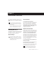
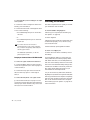
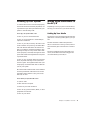
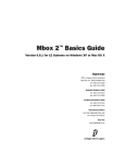
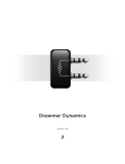
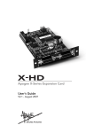
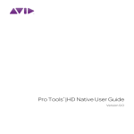
96 I/O
Guide
Digidesign
2001 Junipero Serra Boulevard
Daly City, CA 94014-3886 USA
tel: 650·731·6300
fax: 650·731·6399
Technical Support (USA)
650·731·6100
650·856·4275
Product Information (USA)
650·731·6102
800·333·2137
International Offices
Visit the Digidesign Web site
for contact information
Web Site
www.digidesign.com
Copyright
This guide is copyrighted ©2002 by Digidesign, a division of
Avid Technology, Inc. (hereafter “Digidesign”), with all rights
reserved. Under copyright laws, this guide may not be
duplicated in whole or in part without the written consent of
Digidesign.
DIGIDESIGN, AVID and PRO TOOLS are trademarks or
registered trademarks of Digidesign and/or Avid Technology,
Inc. All other trademarks are the property of their respective
owners.
All features and specifications subject to change without
notice.
PN 910609282-00 REV B 09/03
Communications & Safety Regulation Information
Compliance Statement
The model 96 I/O complies with the following standards
regulating interference and EMC:
• FCC Part 15 Class A
• EN55103 – 1, environment E4
• EN55103 – 2, environment E4
• AS/NZS 3548 Class A
Radio and Television Interference
This equipment has been tested and found to comply with the
limits for a Class A digital device, pursuant to Part 15 of the
FCC Rules.
Communications Statement
This equipment has been tested to comply with the limits for a
Class A digital device. Changes or modifications to this product
not authorized by Digidesign, Inc., could void the Certification
and negate your authority to operate the product. This product
was tested for CISPR compliance under conditions that
included the use of peripheral devices and shielded cables and
connectors between system components. Digidesign
recommends the use of shielded cables and connectors
between system components to reduce the possibility of
causing interference to radios, television sets, and other
electronic devices.
Safety Statement
This equipment has been tested to comply with USA and
Canadian safety certification in accordance with the
specifications of UL Standards; UL1419 and Canadian CSA
standard; CSA C22.2 No.1-M90. Digidesign Inc., has been
authorized to apply the appropriate UL & CUL mark on its
compliant equipment.
Important Safety Instructions
When using electric or electronic equipment, basic precautions
should always be followed, including the following:
• Read all instructions before using this equipment.
• To avoid the risk of shock, keep this equipment away from
rain water, and other moisture. Do not use this equipment
if it is wet.
• The equipment should only be connected to the correct
rating power supply as indicated on the product.
• Do not attempt to service the equipment. There are no
user-serviceable parts inside. Please refer all servicing to
authorized Digidesign personnel.
• Any attempt to service the equipment will expose you to a
risk of electric shock, and will void the manufacturer’s
warranty.
• The product should be connected only to the correct power
supply as indicated on the product.
Warning!
• HD audio interfaces need room at their sides to maintain
proper air flow and cooling.
• Do not install these units into a rack or other enclosure that
doesn't leave room on either side for the unit fans.
• Do not block the sides of the units (where fans are), or
disconnect the fan.
• If the units are racked up in a case, remove all lids, doors,
or covers before operating the units.
• Failure to do so can result in the units overheating very
quickly, which can permanently damage them.
contents
Chapter 1. Introduction to the 96 I/O . . . . . . . . . . . . . . . . . . . . . . . . . . . . . . . . . . . . . . . . . 1
What’s Included . . . . . . . . . . . . . . . . . . . . . . . . . . . . . . . . . . . . . . . . . . . . . . . . . . . . . . . . . 1
System Requirements . . . . . . . . . . . . . . . . . . . . . . . . . . . . . . . . . . . . . . . . . . . . . . . . . . . . . 1
About This Guide . . . . . . . . . . . . . . . . . . . . . . . . . . . . . . . . . . . . . . . . . . . . . . . . . . . . . . . . . 2
About www.digidesign.com . . . . . . . . . . . . . . . . . . . . . . . . . . . . . . . . . . . . . . . . . . . . . . . . . 2
Chapter 2. 96 I/O Hardware Overview . . . . . . . . . . . . . . . . . . . . . . . . . . . . . . . . . . . . . . . . . 3
96 I/O Front Panel . . . . . . . . . . . . . . . . . . . . . . . . . . . . . . . . . . . . . . . . . . . . . . . . . . . . . . . 3
96 I/O Back Panel . . . . . . . . . . . . . . . . . . . . . . . . . . . . . . . . . . . . . . . . . . . . . . . . . . . . . . . 5
Chapter 3. Installation Overview . . . . . . . . . . . . . . . . . . . . . . . . . . . . . . . . . . . . . . . . . . . . . . 9
Installing the 96 I/O . . . . . . . . . . . . . . . . . . . . . . . . . . . . . . . . . . . . . . . . . . . . . . . . . . . . . . 9
Checking Installation . . . . . . . . . . . . . . . . . . . . . . . . . . . . . . . . . . . . . . . . . . . . . . . . . . . . . 10
Powering Up Your System . . . . . . . . . . . . . . . . . . . . . . . . . . . . . . . . . . . . . . . . . . . . . . . . . 11
Making Signal Connections to the 96 I/O . . . . . . . . . . . . . . . . . . . . . . . . . . . . . . . . . . . . . . 11
Example Studio Setup with a Mixing Console . . . . . . . . . . . . . . . . . . . . . . . . . . . . . . . . . . . . 12
Example Studio Setup without a Mixing Console . . . . . . . . . . . . . . . . . . . . . . . . . . . . . . . . . 13
Setting Operating Levels . . . . . . . . . . . . . . . . . . . . . . . . . . . . . . . . . . . . . . . . . . . . . . . . . . 14
Appendix A. Card Removal and Replacement . . . . . . . . . . . . . . . . . . . . . . . . . . . . . . . . . . 17
Removing an I/O Card . . . . . . . . . . . . . . . . . . . . . . . . . . . . . . . . . . . . . . . . . . . . . . . . . . . . 17
Hardware Setup Changes . . . . . . . . . . . . . . . . . . . . . . . . . . . . . . . . . . . . . . . . . . . . . . . . . . 19
Replacing an I/O Card . . . . . . . . . . . . . . . . . . . . . . . . . . . . . . . . . . . . . . . . . . . . . . . . . . . . 19
Index . . . . . . . . . . . . . . . . . . . . . . . . . . . . . . . . . . . . . . . . . . . . . . . . . . . . . . . . . . . . . . . . . . . . . 23
Contents
iii
iv
96 I/O Guide
chapter 1
Introduction to the 96 I/O
The Digidesign 96 I/O is a 16-channel digital audio interface, featuring 24-bit analog-to-digital
(A/D) and digital-to-analog (D/A) converters.
The 96 I/O supports sampling rates of up to
96 kHz for superior dynamic range and low
noise floor.
What’s Included
• 96 I/O with power cable
• This guide
• DigiLink cable (18 inches [0.46m])
• BNC cable (1.5 feet [0.46m])
96 I/O Features
• 16 discrete channels of input and output,
with 4-segment LED meters on each channel.
Input and Output channels can include:
• Eight channels of 24-bit D/A and A/D converters for superior analog input and output at sampling rates of 44.1 kHz, 48 kHz,
88.2 kHz, and 96 kHz.
• S/PDIF, AES/EBU, and Optical (ADAT) digital inputs and outputs.
• Word Clock input and output for synchronizing 96 I/O with external Word Clock or 256x
(Slave Clock) devices.
• Simultaneous use of up to six 96 I/O units is
supported, for a maximum of 96 channels of
I/O at 48 kHz.
• Legacy port for Digidesign MIX-series audio
interfaces.
System Requirements
The Digidesign 96 I/O requires:
• A Pro Tools|HD-series system on a Digidesign-qualified Macintosh or Windows computer.
• Pro Tools software, version 5.3 or higher.
• A monitoring system (mixer, amplifier,
speakers, or headphones).
Digidesign can only assure compatibility and
provide support for hardware and software it
has tested and approved. For a list of Digidesignqualified computers, operating systems, and
third-party devices, refer to the latest compatibility information on the Digidesign Web site
(www.digidesign.com/compato).
• Interface with digital mixing consoles and
other peripherals equipped with ADAT Lightpipe connections (using the ADAT Optical
standard at up to 24-bit resolution).
Chapter 1: Introduction to the 96 I/O
1
About This Guide
About www.digidesign.com
This guide provides a basic overview of the
96 I/O’s features and functionality.
The Digidesign Web site (www.digidesign.com)
is your best source for information to help you
get the most out of your Pro Tools system. The
following are just a few of the services and features available.
Complete instructions for connecting and configuring your Pro Tools|HD-series system are located in the Getting Started with HD Guide.
Conventions Used in This Guide
Digidesign guides use the following conventions to indicate menu choices and key commands:
Convention
Action
File > Save
Session
Choose Save Session from the
File menu
Control+N
While pressing the Control key,
press the N key
Control-click
While pressing the Control key,
click the mouse button
Right-click
(Windows)
Click with the right mouse button
The following symbols are used to highlight important information:
User Tips are helpful hints for getting the
most from your system.
Important Notices include information that
could affect your data or the performance of
your system.
Shortcuts show you useful keyboard or
mouse shortcuts.
Cross References point to related sections in
other Digidesign guides.
2
96 I/O Guide
Support Contact Digidesign Technical Support
or Customer Service; download software updates and the latest online manuals; browse the
Compatibility documents for system requirements; search the online Answerbase; join the
worldwide Pro Tools community on the Digidesign User Conference.
Training and Education Become a certified
Pro Tools Operator or Expert; study on your
own using courses available online, or find out
how you can learn in a classroom setting at a
certified Pro Tools Training Center.
Products and Developers Learn about Digidesign
products; download demo software; learn about
our Development Partners and their plug-ins,
applications, and hardware.
News and Events Get the latest news from
Digidesign; sign up for a Pro Tools demo.
To learn more about these and other resources
available from Digidesign, visit our Web site
(www.digidesign.com).
chapter 2
96 I/O Hardware Overview
96 I/O Front Panel
96 I/O Front Panel
The 96 I/O has the following front panel
features:
Power Switch and LED Ring
This button turns the 96 I/O on and off.
The LED ring around the power button lights
green when the unit has powered up successfully and is connected to an active
Pro Tools|HD-series system. If the LED ring is orange, the unit has power, but the computer it is
connected to is shut down.
Sample Rate LEDs
These LEDs display the current sample rate of
the 96 I/O internal crystal oscillator, which can
be 44.1 kHz, 48 kHz, 88.2 kHz, and 96 kHz. The
sample rate can be set when you create a new
session, or in the Hardware Setup or Playback
Engine dialogs if no session is open.
Chapter 2: 96 I/O Hardware Overview
3
Loop Master LED
The LOOP MASTER LED indicates which
Pro Tools|HD-series audio interface is the master
Pro Tools peripheral. Loop Master defaults to
the first HD I/O connected to the HD Core card.
Loop Master will always be lit with a single interface, regardless of the synchronization mode.
Only one HD I/O can be Loop Master at a time.
When you change the clock source to an external clock on a particular HD I/O, that I/O will
automatically become the Loop Master and all
other HD I/Os in the chain will be switched to
Loop Slave mode. The Loop Master LED will be
continuously lit on the current Loop Master peripheral only, and unlit on all other peripherals.
Sync Mode LEDs
The SYNC MODE LEDs indicate different clock
source modes. Synchronization mode LEDs reflect the Clock Source choice in Pro Tools.
The SYNC MODE LEDs indicate the current
clock source.
INT (Internal) This is the 96 I/O standard clock
setting. In this mode, the 96 I/O sample clock is
generated by its internal crystal oscillator, as determined by the session Sample Rate.
DIG (Digital) This setting indicates that an external AES/EBU, Optical (ADAT), or S/PDIF device
is providing system clock.
4
96 I/O Guide
LOOP (Loop Master) This LOOP LED indicates
that the 96 I/O is slaving to another HD I/O
through Loop Sync.
EXT (External) This setting indicates that 96 I/O
is using the EXT CLOCK IN port for system synchronization. External Clock input and output
do not have to be at the Word clock rate.
For more information, see the Getting Started
Guide that came with your system.
Input and Output LEDs and Meters
16 sets of four-segment LEDs indicate signal
level for each of the 96 I/O’s 16 channels.
These meters are calibrated at –42 dB, –18 dB,
–6 dB, and 0 dB, respectively.
Note that 0 dB is not to be confused with
clipping; please use the on-screen meters in
Pro Tools to determine whether a signal is
clipping. See the Getting Started with HD
Guide.
Two additional LEDs, located to the left of the
meters, indicate whether the meters display input or output levels; the meters indicate output
levels by default, and can be switched from
within the Hardware Setup dialog in Pro Tools.
96 I/O Back Panel
96 I/O Back Panel
The 96 I/O has the following back panel connectors:
Analog Audio Inputs
The 96 I/O has eight balanced, 1/4-inch TRS
jacks for analog audio input connections. These
inputs feature 24-bit A/D converters.
The TRS inputs are wired as follows:
■
Tip = positive
■
Ring = negative
■
Sleeve = ground
These connectors also support unbalanced connections.
Input operating levels are switchable between
+4 dBu and –10 dBV operation. Unbalanced
connections are supported with the use of standard 1/4-inch mono phone plugs.
Analog Audio Outputs
The 96 I/O has eight balanced/unbalanced, 1/4inch TRS jacks for analog audio output connections. These outputs feature 24-bit D/A converters.
All eight output channels are continuously active. Output operating levels are switchable between +4 dBu and –10 dBV operation from
within the Hardware Setup window in
Pro Tools. Unbalanced connections are supported with the use of standard 1/4-inch mono
phone plugs.
AES/EBU Digital In and Out
These are balanced, three-conductor XLR connectors that accept and output a stereo, 24-bit
AES/EBU digital data stream. These two ports
support up to 96 kHz sample rates.
S/PDIF Digital In and Out
These are unbalanced, two-conductor RCA jacks
that accept and output a stereo S/PDIF digital
data stream. S/PDIF supports up to 24-bit audio,
at sample rates up to 96 kHz. To avoid RF interference during S/PDIF transfers, use 75-ohm coaxial cable.
Chapter 2: 96 I/O Hardware Overview
5
Loop Sync In and Out
EXT. CLOCK In and Out
Loop Sync is a dedicated clock loop for synchronizing multiple Pro Tools|HD-series interfaces
together. Loop Sync uses a word clock signal
based on sampling rates of either 44.1 kHz or
48 kHz. As sample rates increase in the system,
Loop Sync continues to operate at a base rate of
44.1 kHz or 48 kHz, depending upon the higher
rate.
The External Clock I/O ports are standard BNC
connectors that receive and output a word clock
signal. These ports can be used to synchronize
the 96 I/O to any device that requires (or provides) word clock.
The Loop Sync In and Out ports are standard
BNC connectors that output a 1x Loop Sync
clock signal. Loop Sync should only be used to
chain multiple Pro Tools|HD-series peripherals
together.
The External Clock In port is configured by your
choice for Clock Source in the Hardware Setup
dialog. The External Clock Out is configured using the External Clock Out selector in the Hardware Setup dialog.
Because crucial timing data is passed
through the Loop Sync and Word Clock ports,
you should use high-quality, 75-ohm RG-59
cables for making connections.
Optical (ADAT) In and Out
The Optical ports accept up to eight channels of
Optical (ADAT) input and output, or two channels (stereo) optical S/PDIF input and output.
Optical (ADAT) mode supports sample rates up
to 48 kHz. In TOS-Link mode, the 96 I/O supports two-channel Optical input and output at
sample rates up to 96 kHz.
About Lightpipe-Compatible Devices
Lightpipe is an industry standard, eight-channel
optical digital audio connection created by Alesis. Lightpipe is found on many devices, including Optical (ADAT) decks, modular digital
multitracks (MDMs), sound cards, A/D or D/A
converters, and digital consoles.
6
96 I/O Guide
AC Power
This connector accepts a standard AC power cable. The 96 I/O is auto power-selecting (100V to
240V) and will automatically work with a standard modular cable to connect to AC power receptacles in any country.
Primary Port
The Primary port is where the DigiLink cable
connects from your HD Core or Process card to
the 96 I/O. The Primary DigiLink port sends and
receives all 32 I/O channels to and from the HD
Core or Process card. As the 96 I/O is a 16-channel only device, channels 17–32 are passed
through to the Expansion port or the Legacy
port.
Expansion Port and Legacy Port
Legacy and Expansion Peripheral Port
Limitations
Expansion Port
The Expansion port is where the DigiLink cable
connects an additional HD I/O to your base, or
primary, HD I/O. This port passes channels
17–32 to the secondary, or expansion, I/O.
Legacy Port
This port is used to connect MIX-series Digidesign audio interfaces to 96 I/O. You can connect
two eight-channel interfaces (such as the 888|24
or 882|20) or a single sixteen-channel interface
(1622 I/O, 24-bit ADAT Bridge I/O, or the original ADAT Bridge I/O) for expanded input and
output options, using their original cables.
Because both the Legacy port and the Expansion
port use channels 17–32, you can only use one
at a time.
To select the Legacy or Expansion ports, refer to
the Pro Tools Reference Guide.
The Legacy port is not available in any session in
which the sample rate is set for higher than
48 kHz.
Accessory Port
This port is not supported at this time.
When the Legacy port has been activated from
within Pro Tools, your MIX-series I/O will appear as channels 17–32 in the Pro Tools mixer.
To connect HD or Legacy audio interfaces, refer
to the Getting Started with HD Guide.
Chapter 2: 96 I/O Hardware Overview
7
8
96 I/O Guide
chapter 3
Installation Overview
This chapter provides basic instructions for installing a 96 I/O, and configuring its operating
levels.
See the Getting Started with HD Guide for
complete system installation and configuration instructions.
If you are adding the 96 I/O to an existing
system, see the Expanded Systems Guide.
Power Connection
To connect AC power to the 96 I/O:
■ Using the AC power cable included with the
96 I/O, connect the 96 I/O to a standard AC
power receptacle. The 96 I/O is auto power-selecting (100V to 240V), and will work automatically when plugged into an AC power
receptacle in any country.
DigiLink Cable Connections
Installing the 96 I/O
All installations require the following AC Power
and DigiLink connections. Expanded systems
also require Loop Sync connections.
Before You Begin
Turn off your computer, hardware interfaces,
monitoring system, hard drives, and peripherals. Making connections while power is on
can damage your system.
DigiLink cable connections differ depending on
whether the 96 I/O is the only audio interface in
the system, or if it is being added as an expansion I/O to an existing Pr Tools|HD system.
The DigiLink cable provided with the 96 I/O is
18 inches long. You can purchase optional DigiLink cables of differing lengths (12 inches, or
25-, 50-, or 100-feet), depending on the needs of
your studio configuration.
To connect the 96 I/O as the only interface in a
new Pro Tools system:
1 Connect one end of the included DigiLink ca-
ble to the Primary port on the 96 I/O.
2 Connect the other end of the DigiLink cable
to the DigiLink port on the HD Core card.
See the Getting Started with HD Guide for
complete system installation instructions.
Chapter 3: Installation Overview
9
To connect the 96 I/O to an existing Pro Tools|HDseries system:
Checking Installation
1 Connect one end of a DigkLink cable to the
Primary port of the 96 I/O.
This section explains how to quickly check that
your installation was successful.
2 Connect the other end of the DigiLink cable
to one of the following:
To check installation using DigiTest:
• An available DigiLink port on an HD Process card.
1 Start up your computer (see “Powering Up
– or –
2 Launch DigiTest.
• An available Expansion port on the existing HD I/O.
If you have at least one 192 I/O or
192 Digital I/O in your system configuration, it must be the primary audio interface
and Loop Sync master.
For additional information, see the Expanded Systems Guide.
Loop Sync Connections with BNC Cable
To connect Loop Sync between two interfaces:
1 Connect the BNC cable from the Loop Sync
Out of the original HD I/O to the Loop Sync in
of the new 96 I/O.
2 Connect the Loop Sync Out from the new
96 I/O to the Loop Sync In of the original
HD I/O.
To connect the 96 I/O into a Loop Sync chain:
■ Connect the new 96 I/O Loop Sync In and
Out ports to properly place the new interface in
the Loop Sync chain. See the Getting Started with
HD Guide for more information.
10
96 I/O Guide
Your System” on page 11).
3 Ensure that any and all HD cards and HD I/Os
are identified properly. If not, see the Getting
Started with HD Guide.
4 When finished, quit DigiTest and restart.
To check or reconfigure I/O:
1 Launch Pro Tools and choose Setup > Hard-
ware Setup.
2 Use the Identify button to verify that your
newly-added 96 I/O has been properly identified. Select each HD I/O in the Peripherals list,
and click on the Identify radio box in the lower
left corner of the Hardware Setup dialog to illuminate all of the LEDs on the front panel. This
will clearly demonstrate which HD I/O you
have selected in the Peripherals list.
3 If you encounter any difficulties, delete the
DigiSetup file (located in the System Folder/Preferences), power down the computer completely,
and turn off all interfaces. Then turn the power
back on all interfaces and boot the computer.
See “Powering Up Your System” on page 11 for
more information.
Powering Up Your System
In order for Pro Tools to communicate properly
with audio interfaces and other peripherals, it is
important that you start up and shut down your
system in the following order:
Power up your system in this order:
1 Turn on your Pro Tools hard drives.
2 Turn on synchronization or other MIDI pe-
Making Signal Connections to
the 96 I/O
Depending on how you plan to use the 96 I/O,
the way you connect it to your studio will vary.
Setting Up Your Studio
The figures on the following pages provide suggestions for connecting studio gear to your system.
ripherals or interfaces.
3 Turn on your 96 I/O and any other Pro Tools
audio interfaces. On power up, the status LEDs
will flash. Wait at least fifteen seconds for the
96 I/O to initialize, and the status LEDs to stop
blinking and stay lit on any and all audio interfaces. If properly connected, the ring around the
power switch will be orange while the computer
is powered down.
The first illustrates a studio setup with the
96 I/O connected to a mixing console, with effects and other gear routed into the console as
well.
The second diagram shows a setup without a
mixer, where effects and monitoring gear are
connected directly to the 96 I/O.
4 Turn on your computer. When the computer
boots, all power LED rings on HD I/O should
switch to green. This signifies that the HD I/Os
are properly connected to HD cards or other HD
I/Os in your system.
MIX-series audio interfaces will not be available
until they have been made active in the Hardware Setup dialog. See the Getting Started with
HD Guide for info.
Power down your system in this order:
1 Quit Pro Tools.
2 Shut down the computer.
3 Power off your audio interfaces.
4 Turn off any synchronization, MIDI, or other
peripherals or interfaces.
5 Turn off your drives.
Chapter 3: Installation Overview
11
Example Studio Setup with a
Mixing Console
Digital Inputs/Outputs
To DAT Recorder
DAT Recorder
optical in/out
to ADAT
Analog
Audio
Inputs
ADAT
Analog
Audio
Outputs
Digital Effects Device
(set to external sync)
Effects Devices
Channel
Outputs
Tape Returns
or Inputs
Instruments
Connected to Console
Example Studio Setup with a Mixing Console
12
96 I/O Guide
Power Amp
and Speakers
Example Studio Setup
without a Mixing Console
Mic, Preamp,
Direct Box, Synth, etc.
Digital Inputs/Outputs
To DAT Recorder
Analog
Audio
Inputs
DAT Recorder
Optical in/out
to ADAT
Analog
Audio
Outputs
ADAT
Analog
Audio
ins/outs
Digital Effects Device
(set to external sync)
Other Effects Devices
Power Amp
and Speakers
Example Studio Setup without a Mixing Console
Chapter 3: Installation Overview
13
Setting Operating Levels
There are specific windows within the Pro Tools
Hardware Setup dialog in which to make I/O settings specific to your 96 I/O. These include setting input and output operating levels.
Consider the following when connecting a
mixer:
◆ If your mixer cannot handle more than 1.5V
(RMS) inputs at +4 dBu, then you should set the
96 I/O to operate at –10 dBV line level.
◆ If your mixer can handle up to 6.15V (RMS)
inputs, or has pads or attenuators on its inputs,
then you can use the +4 dBu setting on the
96 I/O.
◆ 96 I/O is calibrated for 14 dB headroom at the
+4 dBu setting.
Hardware Setup dialog with 96 I/O as the Primary
audio interface
Most manuals contain device input specifications, including whether or not there are pads or
attenuators. Consult the manufacturer’s documentation for your mixer or power amplifier for
further information.
Choosing +4 dBu or –10 dBV
Operating Levels
Selecting Analog Input Operating
Levels
It is important that you determine which line
level is appropriate for your studio. In +4 dBu
operating mode, the 96 I/O is a 24-bit digital
audio device capable of producing audio signals
up to + 18 dBu across +4 dBu input/output. The
default headroom value is 14 dB. This translates
to a maximum output of + 18 dBu.
If you want to switch the input levels of the
96 I/O from +4 dBu to –10 dBV, you can access
these parameters, on a channel-by-channel basis, in the Hardware Setup dialog.
Check the owner’s manual for your mixer,
power amplifier or effects processor to see if it
can handle this load. If the other devices in your
studio cannot handle this load, consider lowering the headroom value of Pro Tools.
2 Choose Setups > Hardware Setup in Pro Tools.
To Set Input Operating Levels:
1 Launch Pro Tools.
About Input Operating Levels
As with Output levels, check the owner’s manual for your mixer, power amplifier or effects
processor to see if it operates more comfortably
at line level, in which case consider setting the
96 I/O to operate at –10 dBV line levels.
14
96 I/O Guide
Selecting +4 dBu or –10 dBV levels in the Hardware
Setup Dialog
3 Click on the Analog In tab to access the radio
buttons with which to select your input operating levels for each channel.
4 Click OK to leave the Hardware Setup dialog.
See the Getting Started with HD Guide for
complete system configuration instructions.
Chapter 3: Installation Overview
15
16
96 I/O Guide
appendix a
Card Removal and Replacement
Removing an I/O Card
In the event of a problem with the A/D or D/A
cards in your 96 I/O, you can remove the card
and send it to Digidesign for repair.
3 Remove all of the 16 small phillips-head
screws around the edges of the top cover. Don’t
lose the screws -- put them in a safe place!
The modular nature of the HD system lets you
simply return the specific card, instead of the
entire 96 I/O. Your HD system will continue to
function while missing a single card. It will not
function if more than one of the factory-installed cards is removed.
Before handling any of the cards or internal
components of 96 I/O, discharge any static
electricity by touching the outer casing of the
power supply.
To remove an I/O card from the 96 I/O:
1 Power off and disconnect the 96 I/O from
Removing the top cover screws
4 Lift off the top of the 96 I/O and set aside.
5 Gently pull the 50-pin connector off of the
edge of the card.
your HD system.
2 Make sure that the 96 I/O is plugged in so that
it is grounded.
Appendix A: Card Removal and Replacement
17
6 Remove the five screws on the front plate of
the card to be removed.
8 Pull the card out by gripping the edges be-
tween your thumb and forefinger on each side.
Pull straight back, lifting very slightly to avoid
contact between components on the underside
of the card and the 96 I/O back panel faceplate.
7 To discharge any static electricity, touch the
power supply casing. It is a good idea to do this
often, throughout the process.
9 Place the card immediately in an anti-static
bag and send it to Digidesign according to instructions from the Customer Support dept.
When you pull a card out, pay particular attention to keeping components on the surfaces of the card from bumping into any of
the internal components or the back panel
faceplate on the 96 I/O.
Touching power supply casing to discharge any
static electricity
18
96 I/O Guide
Hardware Setup Changes
6 Look into the empty bay to locate the guide
rails for the card to slide in on.
When Removing a Card
In this case, the Hardware Setup dialog will reflect the change by setting the removed inputs
and outputs to None. The remaining inputs and
outputs will function normally.
For example, if you remove the Analog Input
card, the Analog Input tab will disappear from
the Hardware Setup dialog.
You will also lose the configuration of any pairs
of inputs or outputs that were assigned to the
card being removed.
Example of an empty bay. Note guide rails along the
inside edge
Replacing an I/O Card
To replace a card:
1 Power off and disconnect the 96 I/O from
your HD system.
2 Make sure that the 96 I/O is plugged in so that
it is grounded.
3 Remove the top cover of the 96 I/O by extracting all of the 16 small phillips-head screws
around the edges of the top cover, and lifting it
off.
4 If the card you are replacing is still connected
to the 96 I/O, see “Removing an I/O Card” on
page 17.
5 To discharge any static electricity, touch the
power supply casing. It is a good idea to do this
often, throughout the process.
Placing the edge of the card into the guide rails
7 Slide the edges of the card into the guide rails
on each side of the bay. Push the card all the way
in until the card’s faceplate is nearly flush with
the rear panel of the 96 I/O.
8 Screw the card’s faceplate onto the rear panel
surface of the 96 I/O with the same screws you
removed from the empty bay cover.
Appendix A: Card Removal and Replacement
19
9 Locate the raised ridge in the middle of the 50pin cable which connects to the 96 I/O chassis.
This ridge is only on one side of the connector,
and there is a matching groove on only one side
of the 50-pin connector on the card.
11 Place the top cover onto the 96 I/O and replace the screws that you removed with it.
12 Connect the 96 I/O to your HD system.
13 Press the Power switch.
14 When you power on the unit, the power LED
should turn orange.
15 Start up the computer.
16 When you boot up the computer, the power
ring should turn from orange to green.
– or –
If it doesn’t, see “Troubleshooting” on page 21.
17 If the ring turns green, and the computer
boots properly, launch Pro Tools.
18 Open the Hardware Setup dialog to confirm
Locating the ridge on the 50-pin cable and the matching
groove on the 50-pin connectors on the card
10 Gently push the cable connector into the
card’s connector. The ridge on the cable connector must be line directly into the groove on the
card connector. Be very careful not to bend any
of the pins.
Pressing the 50-pin cable connector into the card
20
96 I/O Guide
that the new card is recognized:
• If you installed a 96 AD card, you should
see a new tab called Analog In 1–8.
• If you installed a 96 DA card, you should
see a new tab called Analog Out 1–8.
19 If the new card does not appear in the Hardware Setup dialog, power down, check the seating of the card, and recheck the cables inside the
96 I/O.
Troubleshooting
If the power ring does not turn from orange to
green when you boot the computer, make sure
you reconnected the DigiLink cable to the Primary port on the rear of the unit. If the DigiLink
cable is securely fastened and the other end is
plugged into an HD Core or Process card in a
computer that is booted, you may have inadvertently disconnected another 50-pin cable
when installing the card.
Hardware Setup Changes
Whenever a card is removed or replaced, the
Hardware Setup I/O routing reverts to original
defaults.
Appendix A: Card Removal and Replacement
21
22
96 I/O Guide
index
Numerics
E
–10 dBV 14
1622 7
24-bit ADAT Bridge 7
+4 dBu 14
48 kHz 3
882|20 7
888|24 7
96 I/O Back Panel 5
96 I/O Front Panel 3
Example Studio Setup 12
Expansion
DigiLink 7
port 7
External Clock
In 4, 6
In port 6
Out 6
Out port 6
port 4
A
H
AC Power Input 6
Accessory Port 7
ADAT Bridge 7
AES/EBU 4
In/Out 5
Analog Audio Inputs 5
Analog Audio Outputs 5
Hardware Setup 3, 4, 5, 10
headroom 14
B
base rate 6
C
Clock Source 4
D
DIG (Digital) 4
DigiLink
Cable Connections 9
expansion 7
Primary 6
secondary 7
DigiSetup 10
DigiTest 10
I
Identify button 10
Input Operating Levels 14
Installation Overview 9
Installing the 96 I/O 9
INT (Internal) 4
L
Legacy
port 7
Legacy port 7
Lightpipe 1, 6
line level 14
Loop Master 4
Loop Sync 4
chain 10
Connections with BNC Cable 10
In 10
In and Out 6
Out 10
Index
23
M
T
Making Signal Connections to the 96 I/O 11, 12
Meters 4
MIDI 11
peripherals 11
MIX-series
audio interfaces 11
peripherals 7
TOS-Link mode 6
Troubleshooting 21
O
Optical
(ADAT) 6
(S/PDIF) 6
P
Peripherals list 10
Playback Engine 3, 14
Port Limitations
Legacy and Expansion Peripherals 7
power down
order 11
procedures 11
Power Switch and LED Ring 3, 11
power up 11
order 11
procedures 11
Primary
DigiLink 6
port 6
R
RF interference 5
S
S/PDIF 4, 5
sample clock 4
Sample Rate 3, 4
secondary I/O 7
Setting Operating Levels 14
Setting Up Your Studio 11
Sync Mode 4
LEDs 4
synchronization 11
24
96 I/O Guide
U
Unbalanced connections 5
W
word clock 4, 6
Index
25