1
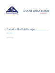
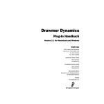
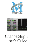
Drawmer Dynamics
Version 7.0
Copyright
© 2005 Digidesign, a division of Avid Technology, Inc. All rights
reserved. This guide may not be duplicated in whole or in part
without the express written consent of Digidesign.
Digidesign, Avid, and Pro Tools are either trademarks or
registered trademarks of Avid Technology, Inc. in the US and
other countries. All other trademarks contained herein are the
property of their respective owners.
Product features, specifications, system requirements, and
availability are subject to change without notice.
PN 9329-17758-00 REV A 10/05
contents
Chapter 1. Introduction . . . . . . . . . . . . . . . . . . . . . . . . . . . . . . . . . . . . . . . . . . . . . . . . . . . . . . 1
Contents of the Boxed Version of Your Plug-In . . . . . . . . . . . . . . . . . . . . . . . . . . . . . . . . . . . . 1
System Requirements . . . . . . . . . . . . . . . . . . . . . . . . . . . . . . . . . . . . . . . . . . . . . . . . . . . . . 2
Register Your Plug-Ins . . . . . . . . . . . . . . . . . . . . . . . . . . . . . . . . . . . . . . . . . . . . . . . . . . . . . 2
Working with Plug-Ins . . . . . . . . . . . . . . . . . . . . . . . . . . . . . . . . . . . . . . . . . . . . . . . . . . . . . 2
Conventions Used in This Guide . . . . . . . . . . . . . . . . . . . . . . . . . . . . . . . . . . . . . . . . . . . . . . 3
About www.digidesign.com . . . . . . . . . . . . . . . . . . . . . . . . . . . . . . . . . . . . . . . . . . . . . . . . . 3
Chapter 2. Installation . . . . . . . . . . . . . . . . . . . . . . . . . . . . . . . . . . . . . . . . . . . . . . . . . . . . . . . 5
Installing Drawmer Dynamics . . . . . . . . . . . . . . . . . . . . . . . . . . . . . . . . . . . . . . . . . . . . . . . . 5
Authorizing Drawmer Dynamics . . . . . . . . . . . . . . . . . . . . . . . . . . . . . . . . . . . . . . . . . . . . . . 5
Removing Expired Plug-Ins . . . . . . . . . . . . . . . . . . . . . . . . . . . . . . . . . . . . . . . . . . . . . . . . . . 7
Chapter 3. Drawmer Dynamics Parameters. . . . . . . . . . . . . . . . . . . . . . . . . . . . . . . . . . . . . 9
Adjusting Parameters . . . . . . . . . . . . . . . . . . . . . . . . . . . . . . . . . . . . . . . . . . . . . . . . . . . . . 9
Expander Module . . . . . . . . . . . . . . . . . . . . . . . . . . . . . . . . . . . . . . . . . . . . . . . . . . . . . . . 10
The Gate Module . . . . . . . . . . . . . . . . . . . . . . . . . . . . . . . . . . . . . . . . . . . . . . . . . . . . . . . . 13
The Compressor Module . . . . . . . . . . . . . . . . . . . . . . . . . . . . . . . . . . . . . . . . . . . . . . . . . . 18
The Limiter . . . . . . . . . . . . . . . . . . . . . . . . . . . . . . . . . . . . . . . . . . . . . . . . . . . . . . . . . . . . 21
Meters and Indicators . . . . . . . . . . . . . . . . . . . . . . . . . . . . . . . . . . . . . . . . . . . . . . . . . . . . 22
Chapter 4. Using Drawmer Dynamics . . . . . . . . . . . . . . . . . . . . . . . . . . . . . . . . . . . . . . . . . 23
Using Plug-Ins as Inserts . . . . . . . . . . . . . . . . . . . . . . . . . . . . . . . . . . . . . . . . . . . . . . . . . . 23
Inserting Drawmer Dynamics on a Track . . . . . . . . . . . . . . . . . . . . . . . . . . . . . . . . . . . . . . . 23
Using the Side-Chain Input in DrawmerGCL . . . . . . . . . . . . . . . . . . . . . . . . . . . . . . . . . . . . . 24
Appendix A. DSP Requirements . . . . . . . . . . . . . . . . . . . . . . . . . . . . . . . . . . . . . . . . . . . . . . 27
Drawmer Dynamics DSP Requirements . . . . . . . . . . . . . . . . . . . . . . . . . . . . . . . . . . . . . . . . 28
Contents
iii
Appendix B. DSP Delays Incurred by TDM Plug-Ins . . . . . . . . . . . . . . . . . . . . . . . . . . . . 29
Drawmer Dynamics DSP Delay . . . . . . . . . . . . . . . . . . . . . . . . . . . . . . . . . . . . . . . . . . . . . 30
Appendix C. Drawmer Dynamics Demo Sessions . . . . . . . . . . . . . . . . . . . . . . . . . . . . . . 31
Using the Demo Sessions . . . . . . . . . . . . . . . . . . . . . . . . . . . . . . . . . . . . . . . . . . . . . . . . . 31
Index . . . . . . . . . . . . . . . . . . . . . . . . . . . . . . . . . . . . . . . . . . . . . . . . . . . . . . . . . . . . . . . . . . . . . 33
iv
Drawmer Dynamics Plug-Ins Guide
chapter 1
Introduction
Thank you for purchasing the Drawmer Dynamics plug-in for Pro Tools|HD systems.
Based in England, Drawmer has a longstanding
reputation for creating high-quality, industrystandard, analog and digital signal processing
devices, including microphone preamplifiers,
esoteric tube equipment, equalizers, and most
significantly, dynamics processors.
The Drawmer Dynamics plug-in is a real-time
TDM plug-in that retains the look and sound of
Drawmer’s renowned hardware units, specifically, the highly-acclaimed Drawmer DS201 and
DL241.
Contents of the Boxed
Version of Your Plug-In
Your Drawmer Dynamics plug-in package contains the following components:
• Installation CD-ROM
• License card (for installing Drawmer Dynamics plug-ins with an iLok USB Smart
Key, not supplied)
• Drawmer Dynamics Plug-Ins Guide (electronic PDF guide)
• Registration information card
There are two configuration of the Drawmer Dynamics plug-in:
• DrawmerECL, providing an Expander,
Compressor, and Limiter
• DrawmerGCL, providing a Gate, Compressor, and Limiter
Chapter 1: Introduction
1
System Requirements
To use Drawmer Dynamics, you need:
◆
A Digidesign-qualified Pro Tools|HD system
Register Your Plug-Ins
If you purchase a plug-in online from the DigiStore (www.digidesign.com) using Internet Activation, you are automatically registered.
– or –
A Digidesign-qualified Pro Tools|HD system
and a third-party software application that supports the TDM plug-in standard
◆
For complete system requirements, visit the
Digidesign Web site (www.Digidesign.com).
The Drawmer Dynamics plug-in does not
support sample rates above 96 kHz.
If you purchase a plug-in boxed version, check
the enclosed information card for information
about how to register online.
Registered users will receive periodic software
update and upgrade notices.
Please refer to the Digidesign Web site
(www.digidesign.com) or the registration card
for information on technical support.
Compatibility Information
Digidesign can only assure compatibility and
provide support for hardware and software it
has tested and approved.
For a list of Digidesign-qualified computers, operating systems, hard drives, and third-party devices, refer to the latest compatibility information on the Digidesign Web site
(www.digidesign.com/compato).
Working with Plug-Ins
Besides the information provided in this guide,
refer to the DigiRack Plug-Ins Guide for general
information on working with plug-ins, including:
• Inserting Plug-Ins on Tracks
• Clip Indicators
• The Plug-In Window
• Adjusting Parameters
• Automating Plug-Ins
• Using the Librarian
2
Drawmer Dynamics Plug-Ins Guide
Conventions Used in This
Guide
All Digidesign guides use the following conventions to indicate menu choices and key commands:
:
Convention
Action
File > Save
Choose Save from the
File menu
Control+N
Hold down the Control
key and press the N key
Control-click
Hold down the Control
key and click the mouse
button
Right-click (Windows)
Click with the right
mouse button
The following symbols are used to highlight important information:
User Tips are helpful hints for getting the
most from your Pro Tools system.
Important Notices include information that
could affect your Pro Tools session data or
the performance of your Pro Tools system.
Shortcuts show you useful keyboard or
mouse shortcuts.
Cross References point to related sections in
the Pro Tools Guides.
About www.digidesign.com
The Digidesign Web site (www.digidesign.com)
is your best source for information to help you
get the most out of your Pro Tools system. The
following are just a few of the services and features available.
Registration Register your purchase online. See
the enclosed registration form for details.
Support Contact Digidesign Technical Support
or Customer Service; download software updates and the latest online manuals; browse the
Compatibility documents for system requirements; search the online Answerbase; join the
worldwide Pro Tools community on the Digidesign User Conference.
Training and Education Become a certified
Pro Tools Operator or Expert; study on your
own using courses available online, or find out
how you can learn in a classroom setting at a
certified Pro Tools Training Center.
Products and Developers Learn about Digidesign
products; download demo software; learn about
our Development Partners and their plug-ins,
applications, and hardware.
News and Events Get the latest news from Digidesign; sign up for a Pro Tools demo.
To learn more about these and other resources
available from Digidesign, visit the Digidesign
Web site (www.digidesign.com).
Chapter 1: Introduction
3
4
Drawmer Dynamics Plug-Ins Guide
chapter 2
Installation
Installing Drawmer Dynamics
Installers for your plug-ins can be downloaded
from the DigiStore (www.digidesign.com) or can
be found on the plug-in installer CD-ROM (included with boxed versions of plug-ins). Additionally, an installer may also be available on a
Pro Tools software bundle CD-ROM.
Authorizing Drawmer
Dynamics
The Drawmer Dynamics plug-in is authorized
using the iLok USB Smart Key (iLok), manufactured by PACE Anti-Piracy, Inc.
Installation steps are essentially the same, regardless of the bundle, package, or system you
purchase.
Installation
To install Drawmer Dynamics:
1 Download and unpack the appropriate plug-
in installer from the Digidesign DigiStore
(www.digidesign.com), or insert the plug-in
installer CD-ROM into your CD-ROM drive.
2 Click Install.
3 When installation is complete, click Finish
iLok USB Smart Key
The iLok is similar to a dongle, but unlike a dongle, it is designed to securely authorize multiple
software applications from a variety of software
developers.
This key can hold over 100 licenses for all of
your iLok-enabled software. Once an iLok is authorized for a given piece of software, you can
use the iLok to authorize that software on any
computer.
(Windows) or Quit (Macintosh).
When you open Pro Tools, you will be
prompted to authorize your new plug-in.
The iLok USB Smart Key is not supplied
with your plug-in or software option. You
can use the one included with certain
Pro Tools systems (such as Pro Tools|HDseries systems), or purchase one separately.
Chapter 2: Installation
5
If you purchased a plug-in online at the DigiStore (www.digidesign.com), you authorize the
plug-in by downloading licenses from iLok.com
to an iLok. See the iLok Usage Guide for details, or
visit the iLok Web site (www.iLok.com).
If you purchased a boxed version of a plug-in,
you authorize the plug-in by inserting the enclosed License Card into an iLok.
Use the following instructions to authorize any
plug-ins that come with an iLok License Card.
3 Follow the on-screen instructions until you
are prompted to insert the License Card into the
iLok.
4 Separate the GSM cutout from the larger pro-
tective card by pulling it up and out with your
thumb. Do not force the cutout down with your
finger.
5 Insert the GSM cutout into the iLok. Visually
verify that the metal portion of the cutout
makes contact with the iLok’s metal card reader.
Authorizing Plug-Ins with an iLok
and a License Card
License Cards are specific to each plug-in or software option. You will receive the appropriate License Cards for the plug-ins that you purchase.
License Cards have a small punch-out plastic
chip called a GSM cutout.
The authorization steps in this section must be
repeated for each plug-in you purchased.
For additional information about iLok technology and authorizations, see the electronic PDF of the iLok Usage Guide.
To authorize a plug-in with the iLok:
1 Insert the iLok into an available USB port on
your computer.
2 Launch Pro Tools. You will be prompted to authorize any installed unauthorized plug-ins or
software options.
If you are already using a demo version of
the plug-in or software option, launch
Pro Tools before you insert the iLok, then
insert the iLok into any available USB port
when prompted by Pro Tools.
6
Drawmer Dynamics Plug-Ins Guide
iLok with License Card
6 Follow the on-screen instructions to complete
the authorization process for each plug-in.
7 After the authorization has completed, re-
move the GSM cutout from the iLok. (If you
have to remove the iLok from the computer to
remove the cutout, be sure to re-insert the iLok
in any available USB port on your computer
when you are finished.)
Removing Expired Plug-Ins
If you let a demo version of a plug-in expire, you
should remove it from your system. Otherwise,
each time you open Pro Tools you will be
prompted with a message that the plug-in has
expired.
Windows
To remove an expired plug-in:
1 Click Start.
2 Click Control Panel.
3 Double-click Add or Remove Programs.
4 Select the expired plug-in from the list of in-
stalled applications.
5 Click the Change/Remove button.
6 Click OK to remove the plug-in.
7 When removal is complete, close the Add or
Remove Programs window.
Mac OS X
To remove an expired plug-in:
1 Open the Plug-Ins folder on your Startup drive
(Library/Application Support/Digidesign).
2 Drag the expired plug-in to the Trash.
3 Empty the Trash.
Chapter 2: Installation
7
8
Drawmer Dynamics Plug-Ins Guide
chapter 3
Drawmer Dynamics Parameters
This chapter explains the parameters of the
Drawmer Dynamics Expander, Gate, and Compressor modules.
Adjusting Parameters
The Drawmer Dynamics plug-in allows several
methods of parameter adjustment.
Editing Parameters with a Mouse
Click and Drag
You can adjust rotary controls with a mouse by
dragging horizontally or vertically. Parameter
values increase as you drag upward or to the
right, and decrease as you drag downward or to
the left.
DrawmerECL plug-in
Increment & Decrement
For incremental parameter adjustment, click the
up or down increment buttons at the right of
each parameter text box.
Using the increment and decrement buttons
DrawmerGCL plug-in
Chapter 3: Drawmer Dynamics Parameters
9
Editing Parameters with a Computer
Keyboard
Each rotary control has a corresponding parameter text field directly below it. This displays the
current value of the parameter. You can edit the
numeric value of a parameter with your computer keyboard.
Expander Module
The Expander is part of the DrawmerECL plugin and is modelled on the Drawmer DL241 and
DS201 hardware processors.
Features
To type a parameter value:
◆ Auto-adaptive attack and release for a more
musical response
1 Click on the parameter text that you want to
edit.
◆ Upward expansion capability with a wide
Threshold
2 Change the value.
◆
Adjustable Ratio with soft-knee options
◆
Gain reduction LED metering
• Type the desired value.
– or –
• To increase a value, press the Up Arrow on
your keyboard. To decrease a value, press
the Down Arrow on your keyboard.
3 Press Enter on the numeric keyboard to input
the value and remain in keyboard editing mode.
– or –
Press Enter on the alpha keyboard (Windows) or
Return (Macintosh) to enter the value and leave
keyboard editing mode.
To move from a selected parameter to the
next parameter, press the Tab key. To move
backward, press Shift+Tab.
Enabling Switches
To enable a switch, click on the switch.
Expander
A common problem with compression is that
maximum gain compensation occurs during extremely quiet passages or during pauses. This results in an increase of background noise, the degree of which depends on the amount of
compression applied.
The accepted way of dealing with this problem
is to use an Expander for low-level gating that
keeps quiet passages or pauses in the material
clean. A problem with simple expanders is that
they may undesirably process low-level audio
signals, since the expander has no way of differentiating low-level audio signals from noise.
On a vocal track, for example, this can lead to
the start or ending of words being accidentally
removed, especially if the singer has a wide dynamic range.
10
Drawmer Dynamics Plug-Ins Guide
Auto-Adaptive Expansion
Ratio Control
The Expander has the ability to automatically
adapt its settings to audio material. This mode
of operation is enabled by turning the Ratio
control fully clockwise to the Soft or Softer setting. It automatically varies ratio and release
time depending on the dynamics of the signal
being processed.
The Ratio control sets the amount of attenuation applied to the signal as it decreases below
the Threshold level.
The Expander’s transition from unity gain to
maximum gain reduction is then dependant on
how far the input level exceeds the threshold
setting.
Because the onset of expansion is progressive,
low-level signals will be processed with a lower
ratio of expansion while the residual noise during pauses will be processed with a higher ratio
of expansion (resulting in greater attenuation).
This makes the Expander easier to use effectively
and more likely to preserve desired audio signals
that are only slightly above the residual noise
floor.
Expander Parameters
Threshold Control
The Threshold control sets the level below
which expansion starts to take place. Threshold
range is from –70 dB to +12 dB.
Setting this control above 0 dB permits upwards
expansion, where over-compressed material can
be re-expanded.
Ratio range is from 1.1:1 to 50:1. At 1.1:1 the Expander closes only slightly (an input signal that
is 10dB below the Threshold setting will be output at –11 dB). At 50:1 the Expander functions
like a Gate (an input signal that is 2 dB below
the Threshold setting will be reduced by
100 dB).
To enable the Expander’s ability to automatically adapt its settings to audio material, turn
the Ratio control fully clockwise until either the
Soft or Softer setting appears.
Attack Control
The Attack control sets the rate at which the Expander opens from a closed state. Attack speed
ranges from 100 µS (0.0001 seconds) to 1.5 seconds. A very fast attack time can sometimes produce audible clicks on low frequency signals.
Release Control
The Release control determines the speed at
which the Expander closes to the Range setting
once the input signal has fallen below the
Threshold level. Release ranges from 50 ms to
2.5 seconds.
With slow, legato audio material, very fast release times can result in audible and possibly
undesirable side-effects, due to the gain changing too quickly.
Chapter 3: Drawmer Dynamics Parameters
11
Range Control
To use the Expander:
The Range control sets the level to which the Expander will close, once the input signal has
fallen below the Threshold setting. Range is
from 0 dB (no expansion) to infinity (∞dB). In
general, use a much smaller range setting than
you would with a Gate.
1 Bypass the Compressor by clicking the Com-
Bypass Switch
The Bypass toggle switch bypasses the Expander.
Expander Gain Reduction (GR) Meter
This ten-element LED meter indicates from 0 dB
to 90 dB of gain reduction. The number of illuminated LEDs will change as the Range control
is adjusted, indicating the maximum gain reduction achievable.
Suggestions for Using the
Expander
The fastest way to begin using the Expander is to
choose one of the presets in the Librarian menu.
(See the DigiRack Plug-Ins Guide for details.) Alternatively, create your own settings using the
procedure that follows.
12
Drawmer Dynamics Plug-Ins Guide
pressor Bypass toggle.
2 Select the desired amount of reduction using
the Range control.
3 Set the Attack and Release controls based on
the character of the audio material you want to
expand. For material with long, legato release,
set a long Release. For material with a lots of low
frequency content, set a slow Attack. For sharp,
percussive sounds, set a short Attack.
4 Set the Ratio control based on the character of
the audio material. Try a maximum setting of
2.5:1 for vocals, and higher ratios for dynamic,
full mix material.
5 Adjust the Threshold control until the the vertical VU meter and the Expander Gain Reduction (GR) meter begin to light.
As a rule, the Threshold should be between 6 dB
to 10 dB below the average input level. Use a
section of audio material with pauses and adjust
the threshold to be as low a dB level as possible
while still attenuating the noise during pauses.
Listen carefully to how the sounds come in after
the pauses and how cleanly they fade away
again. If the Expander changes the sound in an
unacceptable way, the Threshold is probably set
too high.
The Gate Module
The Gate is part of the DrawmerGCL plug-in. It
is based on the highly acclaimed Drawmer
DS201 hardware dynamics processor, which was
instrumental in creating many recording effects
that have become industry standard practice
such as the Gated reverb, and enhanced percussive kick-drums.
Features
◆ Variable high-pass and low-pass filters for frequency-conscious gating
Comprehensive envelope control with attack,
hold, release and range
◆
◆
Ultra-fast response time
◆
Comprehensive side-chain filtering
Key listen capability for monitoring the effect
of the Key Filter
◆
◆
LEDs for clear indication of Gate status
◆
Duck mode for voice-overs
Gate Parameters
HF & LF Key Filters
These controls adjust the roll-off frequencies of
the Key filters. The LF or low frequency filter
ranges from 32 Hz to 4 kHz and attenuates signals below the cut-off frequency at 12 dBs per
octave. The HF or high frequency filter ranges
from 250 Hz to 16 kHz and attenuates signals
above the cut-off frequency. When both filters
are used, only the frequency band between the
two settings remains.
These controls do not overlap each other, since
this would produce very little audio output.
Side-Chain/Internal Control
Setting this control to Side-Chain enables sidechain processing. Side-Chain processing permits
triggering of the Gate by a mono source or key
input other than the gated material itself. Setting
this control to internal disables side-chain processing. (See “Using the Side-Chain Input in
DrawmerGCL” on page 24 for more information.)
Key Listen/Normal Switch
Gate
Set this toggle to Key Listen to monitor the audio specified as the key input. (See “Using the
Side-Chain Input in DrawmerGCL” on page 24
for more information.)
Threshold Control
The Threshold control sets the level below
which gating takes place (the level at which the
output of the Key Filter triggers the Gate).
Threshold ranges from –70 dB to 0 dB. Setting
this control fully counter-clockwise closes the
Gate.
Chapter 3: Drawmer Dynamics Parameters
13
For most noise removal applications, set the
Threshold as low as is possible, so that none of
the desired signal is lost.
Attack Control
The Attack control sets the rate at which the
Gate opens from a closed state. Attack ranges
from 20 µS (about 1 sample) to 1.7 seconds.
A very fast attack time can sometimes produce
audible clicks on low frequency signals.
Hold Control
The Hold control determines the amount of
time the Gate is held open after the signal falls
below the Threshold setting. Hold range is from
2 ms to 2.2 seconds. Hold helps prevent spurious re-triggering of the Gate when using fast release times. It is also useful for creating the classic gated reverb sound often applied to drums.
The Hold cycle starts when the Threshold is
crossed. Audio material with slow attacks requires the Hold setting to be at least as long as
the Attack setting for it to complete its attack cycle.
Release Control
The Release control determines the speed at
which the Gate closes to the Range setting after
the input signal has fallen below the Threshold
level. Release range is from 1 ms to 9 seconds.
Longer releases help retain the original envelopes of the gated audio.
Range Control
The Range control sets the level to which the
Gate closes after the input signal has fallen below the Threshold setting.
14
Drawmer Dynamics Plug-Ins Guide
The range is from 0 dB (no gating) to infinity
(fully gated, or no signal).
When Ducking is enabled, the Range control
sets the level to which the signal will be reduced
when open (triggered). For Ducking set this between –3 dB and –12 dB.
Gate/Duck Control
This toggle switch selects the Gate’s mode of operation. In Gate mode, a signal above the
Threshold will cause the Gate to open. In Duck
mode, the audio passes unattenuated until the
signal exceeds the Threshold. Ducking is mainly
for applications such as voice-overs or removal
of pops and clicks.
Bypass Control
The Bypass control bypasses the Gate.
Gate Envelope LED Meter
This traffic light-style LED shows the active state
of the Gate envelope:
• When the Gate is closed, the red LED is lit.
• When the Gate is open, only the green and
yellow LEDs are lit.
• When the input signal falls below the
threshold, the yellow LED will light then
fade over the duration of the release time.
In Duck mode, the green LED indicates an untriggered (resting) state.
Suggestions for Using the Gate
The fastest way to begin using the Expander is to
choose one of the presets available in the Librarian menu. (See the DigiRack Plug-Ins Guide for
details.) Alternatively, create your own settings
using the procedure that follows.
Additional Tips for Effective
Gating
Initially, set the LF Key Filter fully counterclockwise and the HF Key Filter fully clockwise.
This lets you hear the full audio spectrum of the
key input. Set the Range control fully counterclockwise and Key Listen to Normal.
To use the Gate:
1 Bypass the Compressor by clicking the Com-
pressor Bypass toggle.
2 Choose the key input mode (Side-Chain or Internal). If you select Side-Chain, from the Side
Chain Input pop-up, choose the input/bus that
carries the audio you want to use to trigger gating.
With the Release control set at its midway position, and with suitable program material fed
into the Gate module, increase the Threshold
level from its counter-clockwise position until
the Gate starts to operate. This will be indicated
by the LEDs. Pauses in the program should now
be silent. If the Threshold setting is too high, the
Gate will start to cut out desired audio. If so, adjust it as low as possible.
3 To hear the key input audio source you have
selected to control gating, click Key Listen.
4 To filter the key input so that only certain fre-
quencies trigger the plug-in, set the LF Key Filter
and HF Key Filter controls to the desired frequency range.
5 Begin playback. Gating is now controlled by
If the ends of sounds are obviously being truncated, a longer Release time may help. On the
other hand, if unwanted noise is audible after
the desired audio has ended, a shorter Release
time is more appropriate.
Filtering Out Noise
the input/bus you chose as a key input.
6 Select the desired amount of reduction using
the Range control. Typically, set this fully
counter clockwise.
7 Set the Attack, Hold and Release controls. For
material with long legato release, use a long Release time. For material with a lot of low frequency content, use a slow Attack.
8 Adjust the Threshold control until the the vertical VU meter and the LED meters, show gating
activity. As a rule, the Threshold should be
about 3 dB below the average input level to see
and hear the dynamic processing.
There may be circumstances when the program
material contains unwanted random noise or
other sounds. For example, in a multi-miked
drum kit set up, hi-hat will inevitably leak into
the snare microphone, snare drum will leak into
the kick drum microphone, and so on.
Similarly, when processing audio recorded on
location, you may experience problems due to
wind or traffic noise or close-by conversation. If
the unwanted noise is different in pitch to the
desired audio, it is often possible, using Key Listen, to use the filters to tune in to the wanted
sound while excluding as much of the unwanted sound as possible. Used carefully, these
filters can significantly decrease false triggering
of the Gate.
Chapter 3: Drawmer Dynamics Parameters
15
Adjusting Attack Time Effectively
The Attack control has a very wide range. At its
fastest, it can open instantaneously. Conversely,
setting the Gate attack time too fast on material
with a slow or moderate attack can cause clicks,
particularly if the Threshold has to be set high
because of excessive background noise.
This is a common problem with noise gates, especially when processing low-frequency audio
such as bass guitar or bass drum. With a high
threshold, a low frequency sine wave will be ignored as the signal starts from its zero level
point.
As this wave climbs towards its peak, the level
will suddenly exceed the threshold setting. At
this point a very fast attack rate will switch the
signal through the noise Gate with such a steep
(almost vertical) leading edge that the low frequency sound will have a single high frequency
square wave added to its first cycle, causing a
click.
In cases like these, start with a fast attack time
and moderate threshold, then gradually
lengthen the attack time until the click disappears when the Gate opens.
Performing Ducking
Probably the most common form of Ducking is
that used by radio announcers, whereby the volume of the background music being played is
dropped, enabling them to speak over it. In
Duck mode the Gate module can perform this
effect. The music signal is routed to the input
and the announcer's microphone signal is fed
into the key input. (Be sure to set the key input
to Side-Chain.)
16
Drawmer Dynamics Plug-Ins Guide
The Range control is used to set the level to
which the music will drop when the Ducker is
triggered from the key input. The envelope controls determine the rate at which the level will
drop and then recover. It is usual to select a medium to fast Attack time, so that the music level
drops rapidly as soon as the announcer begins
to speak—with a slow Release time of a second
or so.
This will bring the music level back up slowly
and smoothly. Some Hold time will help prevent chattering, when the voice on the key input pauses to breathe. This technique can also
be used to reduce the level of other instruments
during a solo.
Besides voice over applications, the Duck function of the Gate module can also be used to treat
a signal where the peaks are too loud and require attenuating. In this application, Duck and
Side-Chain key input modes should be selected,
and the Range control adjusted to give the desired attenuation to signals above the Threshold
setting. In extreme cases, the ducking action
may be used to attenuate signal peaks, and by
careful use of the filters, it may be possible to remove a snare drum from a drum mix or clicks
and pops from a recording.
For most ducking applications, the lowest practical Threshold setting must be used.
Using a Stereo Gate
When using the Gate on a stereo signal, be
aware that the control signal is derived by averaging the left audio channel with the right audio channel. Where one channel differs significantly from another in a stereo track, better
results may be obtained if the channels are
treated as two mono channels. (For a side-chain
key signal, the control is always a mono signal.)
By setting up a stereo plug-in with one channel
in Gate mode and the other in Duck, the envelope controls can be used to create interesting
triggered panning effects, simply by feeding a
mono signal into left and right channels and
setting the Range control to maximum attenuation.
Difficult Material To Gate
As with any Gate, noise can only be removed
during pauses in the desired material. If noise
contamination is serious enough to be evident
even during moderately loud program material,
simple gating will do little to help. In fact, the
very fact that the Gate produces silence during
pauses can make the noise content of the program material even more apparent. In extreme
cases, restricting the Range of the Gate to about
–15 dB will adequately reduce noise during
pauses but not sufficiently to cause an unacceptably dramatic change in noise level as the Gate
opens and closes.
Creative Use of the Key Input Filters
The key input filters in the Gate may also be
used to good effect in situations where the desired audio does not occupy the full audio spectrum. Conventional equalizers seldom have a
sharp enough response to remove unwanted
noise without also removing desired audio.
Used with electric guitar, this produces little below 100 Hz or above 3 kHz, so setting the Gate
to Key Listen mode will enable you to use the filters to exclude much of the amplifier hum at the
low end and hiss at the top end while having little effect on the sound of the guitar. The same is
true for acoustic guitar. The filters can be used to
reduce fret noise or a player's breathing.
Other applications of the filters include removing unpleasant overtones from direct-injected
instruments and warming up digital synthesizer
sounds.
Tips For Using Key Inputs and Key
Input Filtering
Complicated Keying
For a more intricate and musical key input, combine several tracks together by bussing them to
Auxiliary Inputs.
Leaving Key Listen Enabled
You can use the Gate as a simple filter by enabling Key Listen.
Key Filter Propagation Delay
Key input filtering with high frequency attenuation can cause a slight delay in the time the
Gate takes to trigger. Under most circumstances
this will be imperceptible. However, when transient sounds are being processed with the HF
Key Filter control set to a very low value, some
degradation of the attack transient may become
apparent.
Consequently, always set the HF Key Filter control to the highest possible value when processing percussive sounds and set the Threshold as
low as possible.
Cleaner Keying
It is often useful to use a Drawmer Dynamic
plug-in to process the key input before it is used.
Good results can be achieved by using an Expander (with the Compressor bypassed) on the
key input source. This will give the key input
source a more accentuated difference between
Chapter 3: Drawmer Dynamics Parameters
17
program and silence. With a cleaner key input,
any associated gating will be more defined, and
the Gate’s Threshold settings will be easier to
optimize.
The Compressor Module
The Compressor appears in both the DrawmerECL and DrawmerGCL plug-ins.
Compressor Parameters
Threshold Control
The Threshold control determines the input
level above which gain reduction will be applied. Threshold range is from –64 dB to +0 dB.
Soft knee compression takes place for signals exceeding the threshold level by up to 10 dB.
Above this level, conventional ratio compression is applied.
Features
Wide Threshold range for accurate compression
◆
Ratio Control
◆ Auto-adaptive Attack and Release for a more
musical response
The Ratio control sets the compression ratio applied after the 10 dB soft-knee region of the
Threshold is exceeded.
◆ Adjustable Ratio, ranging from very gentle
compression to absolute Limiting
Ratio ranges from 1.1:1 to infinity. This allows
hard limiting with adjustable attack and release.
◆ Soft knee for progressive and unobtrusive
compression
Attack Control
◆ Automatic Gain Make-up calculates the most
suitable output Gain position for maximum
data dynamic range
◆
Gain reduction meter
The Attack control sets the rate at which the
Compressor will respond to input signals that
exceed the Threshold level setting. Attack
ranges from 100µS to 100 ms.
When Auto Attack and Release is enabled, the
control knobs have no effect.
Auto (Attack & Release) Switch
Compressor
The Compressor combines aspects of both traditional ratio-style compressors and soft-knee
compressors, making it equally adept at creative
work and subtle level control. Traditionally,
soft-knee compressors have been preferable for
subtle level control where the original sound is
changed as little as possible. Ratio-type compressors are generally considered better suited to
creative applications where large amounts of
gain reduction are required.
18
Drawmer Dynamics Plug-Ins Guide
This toggle switch disables the Attack and Release rotary controls and instead optimizes the
Attack and Release times to suit the dynamics of
the material being processed.
Enabling this setting will often produce the subtlest level control on signals with widely varying
dynamics or complete mixes.
Release Control
Auto Gain Make-Up Switch
The Release control sets the rate at which gain
returns to normal after the input signal level has
fallen below the Threshold. Release range is
from 50 ms to 5 seconds.
With Auto Gain Make-Up on, Gain Make Up is
adjusted automatically when the Compressor’s
Threshold, Attack and Ratio or Limiter Threshold are adjusted, so that the output level is as
close as possible to the Limit Threshold.
With very long release settings the Compressor
may not have enough time to recover between
the signal peaks.
With very short release settings low frequency
signals will have a tendency to distort as the
Compressor tries to release on the signal sine
wave.
Gain Control
When set to extremes, the Auto Gain Makeup feature cannot restore enough gain to
make back all the level that would be required to repair excessive Compression.
Compressor Gain Reduction Meter
This nine-element LED-style meter indicates
from 0 dB to 30 dB of gain reduction.
The Gain control has two functions, depending
on the current state of the Auto Gain Make-up
toggle switch. When Auto Gain Make-up is on,
the control has a center-zero and is used as a fine
trim for optimum output level. This should be
centered at 0 dBfs, but can be reduced up to
9 dB, or driven harder, in which case the signal
will hit the Limiter.
Limit Threshold Control
When Auto Gain Make Up is turned on, the gain
control becomes a ±9 dB trim. In manual mode,
up to 36 dB of gain compensation can be added
for level changes caused by Compression.
The Compressor Gain control should be used to
ensure that the Peak Limiter operates rarely, if at
all. Alternatively, you can deliberately drive it
into limiting for creative effects.
In the signal path, this control comes before the
Peak Limiter detector. This fact should be taken
into account when setting the Peak limiter
threshold. Driving the gain too hard will often
produce excessive limiting.
Limit Gain Reduction Meter
The Limit Threshold control sets an absolute
limit in decibels that the output signal is not allowed to exceed. This control is normally left in
its fully clockwise position, where preventative
limiting will sometimes occur with audio material containing high level peaks.
This five-element LED-style meter indicates
from 1 dB to 16 dB of gain reduction. The meter
scale has been designed so that more sensitive
amounts of limiting are displayed, rather than
the maximum available.
Chapter 3: Drawmer Dynamics Parameters
19
Bypass (Compressor and Limiter)
Switch
This toggle switch bypasses the Compressor and
Peak Limiter. Normally it is used to compare the
unprocessed signal with the processed signal.
Suggestions for Using the
Compressor
The fastest way to begin using the Expander is to
choose one of the presets available in the Librarian menu. (See the DigiRack Plug-Ins Guide for
details.)
Alternatively, create your own settings using the
procedure that follows.
To use the Compressor:
1 Bypass the Gate or Expander by clicking their
Bypass toggle.
2 Turn on Auto Attack & Release.
3 Turn on Auto Gain Make-up.
4 Set the Limiter control fully clockwise.
5 Set the Ratio control. For vocals, try 2.5:1 or
less. For full mixes use even less. For dynamic
single tracks, use more.
6 Adjust the Threshold control until the the vertical VU meter and the Compressor Gain Reduction (GR) meter show activity. As a rule, the
Threshold should be 6 dB to 10 dB below the average input level to hear much change.
Additional Suggestions for Using
the Compressor
Setting up the Compressor is simpler if the Expander or Gate is initially set to Bypass and the
Peak Limiter threshold set to maximum. This
lets you adjust the Compressor in isolation.
20
Drawmer Dynamics Plug-Ins Guide
Ratio Amount
The Ratio setting depends on how much the signal dynamics need controlling. As a rule, higher
ratios provide a higher degree of control but also
tend to be more audible in operation when high
levels of gain reduction are required. The softknee feature of the Compressor makes this far
less pronounced. Overall, a higher ratio can be
used than on conventional compressors without compromising the sound quality.
Effective Gain Reduction
If the Attack & Release switch is set to Auto, setting up is simply a matter of adjusting the
Threshold control until the desired amount of
gain reduction occurs. You can judge this partly
by ear and partly by observing the gain reduction meter.
A maximum gain reduction of between 8 dB
and 12 dB is usually adequate. If more gain reduction is necessary, consider applying compression during recording and then further
compression while mixing.
With Auto Gain Make-up disabled, rotate the
Gain control until as near to 0 dB (full scale) signal output is seen at the VU meter. For greater
simplicity, select Auto Gain Make-Up.
Background Noise
Compression during a mix increases the subjective level of background noises during pauses
and quiet passages. Unless the noise problem is
serious, the Expander can attenuate this noise to
a very high degree, without compromising the
desired audio signal.
Attack Times
The longer the attack time, the longer the Compressor takes to respond to increases in signal
level and a slow attack time is often used to accentuate the beginning of percussive or plucked
sounds such as drums, basses and guitars. a long
attack time can also permit peaks to pass unattenuated. The limiter will pick these up, so it is
quite common with slow attack times to see increased limiter activity. A fast attack time will
bring the input signal under control very
quickly.
Pumping
Pumping refers to heavy compression with incorrectly set envelope parameters. This results in
very audible gain changes when the compressor
attacks and releases. It is often an indication
that the release time is too long. Release time
should be set short enough so that the gain has
returned to normal before the next signal peak
occurs, and, in general, it should be set as short
as possible before audible gain pumping occurs.
In most cases, an output of 0 dBfs is the optimum output level. Lower output levels can be
set using the Limiter Threshold. You might want
to do this so that later inserts can better receive
an optimized signal level at their input. If so, set
the Peak Limiter Level to the desired output
value then adjust the Compressor Auto or manual Gain control to ensure minimum Limiter activity.
Peak Limiter Bypass
The Peak Limiter has no bypass control. However, turning the Level control fully clockwise
will prevent virtually all limiting. To use the
Limiter while effectively bypassing the Compressor, turn the Compressor Threshold fully
counter clockwise to its maximum of +0 dB.
Then set the Ratio to its lowest setting of 1.1:1 if
Gain Make-Up is set to manual. Set the Gain to
0 dB if Auto Gain is enabled.
Compensating for Apparent Dullness in
Compressed Material
Compression can sometimes seem to have the
effect of dulling audio material. Most of the energy in typical broadband music is contained
within the bass range. This high energy causes
the Compressor to operate, causing any quieter,
high frequency sounds occurring at the same
time to be reduced in level. That is why the cymbals and hi-hats in a heavily compressed drum
track seem to dip in level whenever a loud bass
drum or snare drum beat occurs.
The solution is to use less compression or increase the attack time to allow the leading edge
of the brighter sounds to pass through the Compressor before gain reduction occurs. Though
the semi-soft-knee compression systems used in
Drawmer Dynamics modules tend to minimize
this effect, in extreme cases, it may be necessary
to add a little artificial brightness to the processed sound using equalization or some form of
exciter.
The Limiter
If the Compressor module is used with higher
ratios, it will function as a Limiter. In addition
to this feature, there is a separate auto-adaptive
Peak Limiter. This not only catches any peaks
that a slow Compressor attack might pass
through unprocessed, but also lets the user set
an absolute output signal level that will not be
exceeded.
Chapter 3: Drawmer Dynamics Parameters
21
Limiting is extremely valuable in digital recording where an absolute maximum recording level
exists. When overdriven with Gain, it can also
be used creatively to produce deliberate levelpumping effects.
Meters and Indicators
Drawmer Dynamics provides several types of
LED-type signal meters and indicators.
VU meter (stereo)
Peak Input LED
The Peak Input LED indicates peaks in input signals. At 1.0 dB below digital full scale the LED is
amber. At –0.01 dB, (just below full scale input)
it is red. If the Peak Input LED frequently flashes
red, the input signal is clipping and should be
reduced.
Stereo Input Balance
This control, which appears only when Drawmer Dynamics is used in stereo, lets you correct
an imbalance between stereo input images without introducing any gain. (Stereo dynamic control is best achieved with a mix that is equally
centered.)
Peak Input LED
VU Meter
Stereo Input Balance control
The sixteen-element LED VU Meter shows output levels after processing. Metering ranges
from 60 dB below full scale to 0 dBfs. Green
LEDs indicate levels below –4 dB. Yellow LEDs
indicate levels from –3 dB to –1 dB. An amber
LED indicates –0.5 dB and turns red for peaks
held at 0 dBfs.
The LEDs show relative input balance and how
far off center the incoming stereo mix is. A perfectly matching stereo input should produce virtually no LED activity, regardless of audio level.
When centered, the Stereo Input Balance control has no effect. Moving the control to the left
attenuates the right input signal by up to 6 dB
and pans the image to the left. Moving the fader
to the right attenuates the left input signal by up
to 6 dB and pans the image to the right.
Peak input LEDs appear at both ends of the
meter.
22
Drawmer Dynamics Plug-Ins Guide
chapter 4
Using Drawmer Dynamics
Drawmer Dynamics is a real-time TDM plug-in.
It processes audio non-destructively in real time.
It does not alter the original source audio, but
only applies its effects during playback.
Inserting Drawmer Dynamics
on a Track
Using Plug-Ins as Inserts
To show inserts in the Mix window:
To use the Drawmer Dynamics plug-in, you
must insert it in-line on an audio track, Auxiliary Input, or a Master Fader.
When more than one insert is used on a track,
they process the audio in series, each effect being added to the previous one, from top to bottom in the Mix window.
Pre-Fader Operation
To use Drawmer Dynamics in a Pro Tools session, add it to a track as an insert.
■
Choose View > Mix Window > Inserts.
To insert Drawmer Dynamics on a track:
1 Click the Inserts selector on a track and select
the plug-in that you want to use.
2 Click Play on the Transport to begin audio
playback.
3 Adjust the parameters of the plug-in for the effect you want.
Drawmer Dynamics functions as a pre-fader insert, meaning that its level is not affected by a
track’s volume fader (except when used on a
Master Fader).
For this reason, clipping can occur if you boost
its gain to extremes. This is particularly true on
tracks recorded at high amplitude. Watch onscreen metering to identify and rectify clipping
if it occurs.
Adding Drawmer Dynamics as an insert
Shortcuts
■ For finer adjustments, Control-drag (Windows) or Command-drag (Macintosh), the desired parameter.
Chapter 4: Using Drawmer Dynamics
23
To return a control to its default value, Altclick (Windows) or Option-click (Macintosh)
the control.
■
To remove Drawmer Dynamics from a track:
■
A common production technique is to use these
controls to filter a drum track so that only specific high frequencies (a hi-hat, for example) or
low frequencies (a tom or a kick, for example)
trigger the gate.
Click the Insert selector and choose No Insert.
Using a Key Input for External
Side-Chain Processing
To use a filtered or unfiltered external key input to
trigger dynamics processing:
Removing Drawmer Dynamics
1 Click the Key Input selector and select the input or bus carrying the audio from the reference
track or external audio source.
Using the Side-Chain Input in
DrawmerGCL
The side-chain is the split-off signal used by a
plug-in's detector to trigger dynamics processing, and is generally drawn internally from the
input signal. However, some plug-ins (such as
the DrawmerGCL) let you switch between internal and external side-chain processing.
With external side-chain processing, a plug-in's
detector is triggered by an external signal (such
as a separate reference track or audio source)
known as the key input.
Selecting a Key Input
2 Set the Key section to the Side-Chain setting.
Key
Listen
Side-Chain
A typical use for this feature is to use a kick drum
track to gate and tighten up a bass track, or a
rhythm guitar track to gate another instrument
track such as a keyboard pad.
Side-Chain Filters
The DrawmerGCL plug-in also features highpass and low-pass side-chain filters, which lets
you can make dynamics processing more or less
sensitive to certain frequencies.
24
Drawmer Dynamics Plug-Ins Guide
LF Key
Filter
HF Key
Filter
Side-chain controls in DrawmerGCL
3 To hear the audio source you have selected to
control side-chain input, click Key Listen.
4 To filter the side-chain input so that only certain frequencies trigger the plug-in, set the LF
Key Filter and HF Key Filter controls to the desired frequency range.
5 Begin playback. The plug-in uses the filtered
input signal to trigger dynamics processing.
6 To fine-tune side-chain triggering, adjust the
plug-in controls.
5 Begin playback. Gating is now controlled by
the input or bus you chose as a key input.
6 Adjust the Noise Gate’s Threshold to fine tune
side-chain triggering.
7 Adjust other parameters to achieve the exact
effect you want.
Using a Filtered Input Signal for
Side-Chain Processing
To use the filtered input signal to trigger dynamics
processing:
1 Ensure the Key Input selector is set to No Key
Input.
2 Set the Key section to the Internal setting.
Internal
LF Key
Filter
Key
Listen
HF Key
Filter
Side-Chain section
3 To hear the audio source you have selected to
control side-chain input, click Key Listen.
4 To filter the side-chain input so that only certain frequencies trigger the plug-in, set the LF
Key Filter and HF Key Filter controls to the desired frequency range.
Chapter 4: Using Drawmer Dynamics
25
26
Drawmer Dynamics Plug-Ins Guide
appendix a
DSP Requirements
The number of TDM plug-ins you can use at one
time depends on how much DSP power is available in your system. Since the TDM hardware on
Pro Tools cards provide dedicated DSP for plugins, plug-in performance isn’t limited by CPU
processing power.
The DSP tables in this appendix show the theoretical number of instances of each plug-in that
can be powered by a single DSP chip on
Pro Tools|HD cards. DSP usage differs according
to card type.
DSP tables show the theoretical maximum
performance when no other plug-ins or system tasks (such as I/O) are sharing available DSP resources. You will typically use
more than one type of plug-in simultaneously. The data in these tables are provided as guidelines to help you gauge the
relative efficiency of different plug-ins on
your system. They are not guaranteed performance counts that you should expect to
see in typical real-world sessions and usage.
There are a total of nine DSP chips on a
Pro Tools|HD card (HD Core, HD Process, and
HD Accel). HD Core and HD Process cards provide identical chip sets. HD Accel cards provide
newer, more powerful DSP chips (making the
HD Accel card ideal for DSP-intensive plug-ins,
and for high sample rate sessions).
Not all plug-ins are supported on all types of
chips. The following tables indicate the number
of compatible chips per card.
Using Multi-Mono Plug-Ins on
Greater-Than-Stereo Tracks
Plug-ins used in multi-mono format on greaterthan-stereo tracks require one mono instance
per channel of the multi-channel audio format.
For example, a multi-mono plug-in used on a
5.1 format track, requires six mono instances
since there are six audio channels in the 5.1 format.
Monitoring DSP Usage
The System Usage window (Window > System
Usage) shows how much DSP is available in your
system and how it is being used in the current
Pro Tools session.
For more information about DSP usage and
allocation, see the Pro Tools Reference
Guide.
DSP Requirements
27
Drawmer Dynamics DSP Requirements
The Drawmer plug-ins have the following DSP requirements:
HD Accel Card
Table 2. Maximum instances of plug-ins per DSP chip for an HD Accel card, at different sample rates,
(mono and stereo).
Sample Rate:
Plug-In
44.1/48 kHz
88.2/96 kHz
Compatible DSP chips per HD Accel
card
Mono
Stereo
Mono
Stereo
DrawmerECL
8
4
4
2
9
DrawmerGCL
8
4
4
2
9
HD Core and HD Process Cards
Table 3. Maximum instances of plug-ins per DSP chip for an HD Core or HD Process card, at different sample rates
(mono and stereo).
Sample Rate:
Plug-In
28
44.1/48 kHz
88.2/96 kHz
Compatible DSP chips per HD Core or
HD Process card
Mono
Stereo
Mono
Stereo
DrawmerECL
4
2
2
1
9
DrawmerGCL
4
2
2
1
9
Drawmer Dynamics Plug-Ins Guide
appendix b
DSP Delays Incurred by TDM Plug-Ins
Virtually all TDM plug-ins incur some amount
of signal delay.
If you are working with mono tracks, or are processing all channels with the same plug-in, the
signal delays are not long enough to be significant and should not be a concern.
This signal delay is significant only if you use a
plug-in on one channel of a stereo or multichannel signal but not the others, since this can
cause the channels to be slightly out of phase.
Table 3 shows the delays inherent in each Drawmer Dynamics plug-in.
Compensating For Delays
Automatic Delay Compensation Pro Tools HD
systems provide automatic Delay Compensation to compensate for signal processing delays. For details, see the Pro Tools Reference
Guide.
Manual Delay Compensation If it becomes necessary to manually compensate for plug-in delay,
use the TimeAdjuster plug-in included with
Pro Tools to offset other tracks, as appropriate.
See the DigiRack Plug-Ins Guide or the Pro Tools
Reference Guide for more information on TimeAdjuster.
Channel Delay Indicator
The Channel Delay Indicator in the Mix window displays the total delay, in samples, incurred on the track from the use of any TDM
plug-in on that channel.
To see the amount of time delay on a track that
uses plug-in inserts.
In the Mix window, Control-click (Windows)
or Command-click (Macintosh) the track’s Volume Indicator to toggle between Volume
(“vol”), Peak (“pk”) and Channel Delay (“dly”)
indications.
■
DSP Delays Incurred by TDM Plug-Ins
29
Drawmer Dynamics DSP Delay
≈
Table 3. Samples of delay incurred by each TDM plug-in
on Pro Tools|HD cards
Plug-In
30
Samples of Delay on
Pro Tools|HD Cards
DrawmerECL
7
DrawmerGCL
7
Drawmer Dynamics Plug-Ins Guide
appendix c
Drawmer Dynamics Demo Sessions
Several demo sessions are included with Drawmer Dynamics. These sessions illustrate how to
use the plug-in during typical recording scenarios.
Using the Demo Sessions
Before opening a demo session, you must have
already installed and authorized the Drawmer
Dynamics plug-in.
“Gated Tones” Demo
This session illustrates keying of two different
tone bursts from an existing short drum loop using the Gate. The three-channel session uses
two Gates. The key input is from the original
drum track.
The unprocessed audio in this session is
very loud. Turn down your monitoring system if you plan to bypass the Gate.
“Snare” Demo
To open a demo session:
1 Locate and open the demo sessions folder
(Digidesign/Drawmer Dynamics/Drawmer Dynamics Demo/Demo Sessions).
2 Double-click the desired demo session.
3 When the session opens, press the Spacebar to
begin playback.
This session illustrates a gated reverb effect using the Gate and a modified variation of
“Gate&Comp Staccato” setting with a reduced
Gate Threshold to compensate for low signal
level. Notice how the reverberated sound is
shortened. Imagine that the reverb could also be
high level noise. Gate Release greatly affects the
output.
4 Click Bypass to compare the track with and
without dynamics processing.
About the Demo Sessions
Following are brief descriptions of each demo
session and the features they illustrate.
“Noise Removal” Demo
This session illustrates how to use the Expander
to effectively remove excessive background hiss
from a short drum loop. Use the Bypass button
to compare the processed and unprocessed audio.
Appendix C: Drawmer Dynamics Demo Sessions
31
“Wrong & Right” Demo
“Extra-Clean-Key & Drum” Demo
This session illustrates the right and wrong way
to use a Gate. The same bass guitar audio appears on two tracks. Both tracks have the same
Gate assigned, but each has differing parameter
settings. Notice that using the wrong Threshold,
Attack, Hold and Release settings can give very
poor results from low frequency signals. Use
Solo and Mute to compare the effect of the right
and wrong settings.
This session illustrates keying of a short drum
loop from a composite track of mixed sine wave
tones. The tone mix is first cleaned using the Expander assigned to the first mixer insert button.
This audio is then used as a key input. The result
is a cleaner key signal for the Gate.
“VoxOver” Demo
This session illustrates how to use the Gate to
perform ducking. Note how the levels of the
music tracks are attenuated whenever the vocal
track comes in. This technique is frequently
used in radio, film, and commercial voice-overs,
or anywhere that automatic control over background pad level is required.
Note that one audio source (the vocal track) is
used to trigger two separate mono backing
tracks by positioning the key selector switch
centrally. In reality, the amount of ducking in
this demo is excessive, and often as little as 3 dB
of attenuation may be sufficient.
The main vocal track utilizes the Expander to remove headphone spill/background noise.
Try inverting the Gate/Duck switch of one of
the Gates. This will result in distinct panning of
the outputs during the duration of the vocal
track.
32
Drawmer Dynamics Plug-Ins Guide
This demo includes automation that shows how
you can vary the Threshold parameter to ignore
a key input.
“Clean & Dirty Drums” Demo
This session illustrates three different styles of
processing using both the Gate and the Expander. There are three audio tracks, each of
which demonstrates a different effect:
◆ The left audio channel (“Rhythm <L”) carries
the original “scratchy” audio. The DrawmerGCL
plug-in is loaded in a bypassed state. Adjusting
the Gate Threshold to about –20 dB will allow
the rest of the drum track to pass through the
plug-in.
◆ The right audio channel (“Rhythm >R”) carries the audio after being bounced and processed. This channel has a DrawmerECL plug-in
that once enabled, demonstrates Upward Expansion. This shows how to add more life to a
track that suffers from an over-squashed dynamic range.
◆ The center channel carries audio that has
been over processed. This shows the kind of effect that can be achieved with this type of double-pass processing.
index
A
adjusting parameters 9
Attack parameter 11, 14, 18
adjusting 16
Auto-Attack and Release 18
authorizing plug-ins 6
Auto Gain Make-Up parameter 19
auto-adaptive expansion 11
Auto-Attack and Release 18
B
boxed version 1
Bypass parameter 12, 14, 20
C
clipping levels 23
Compressor 18
features 18
parameters 18
suggestions for using 20
Compressor Gain Reduction Meter 19
D
decrement buttons 9
delay
DSP-induced delays 29
demo sessions 31
“Clean & Dirty Drums” 32
“Extra-Clean-Key & Drum” 32
“Gated Tones” 31
“Noise Removal” 31
“Snare” 31
“VoxOver” 32
“Wrong & Right” 32
DrawmerECL 1
DrawmerGCL 1
DSP delays inherent in plug-ins 29
DSP requirements 27
ducking 16
E
editing parameters
moving to the next field 10
Expander 10
auto-adaptive expansion 11
features 10
parameters 11
suggestions for using 12
external side-chain processing 24
F
filtering noise 15
G
Gain parameter 19
gain reduction 20
Gain Reduction Meter 12
Gate 13
features 13
gating difficult material 17
parameters 13
suggestions for using 15
using in stereo 16
Gate Envelope LED meter 14
Gate/Duck parameter 14
guide conventions 3
H
help 3
HF & LF Key Filters 13
Hold parameter 14
Index
33
I
R
iLok 6
increment and decrement buttons 9
input signal, filtering with side-chain filters 25
inserting plug-ins on a track 27
inserts 23
Installing Drawmer Dynamics 5
internal side-chain processing 24
Range parameter 12, 14
Ratio parameter 11, 18
registration 2
Release parameter 11, 14, 19
removing Drawmer Dynamics 24
removing expired plug-ins
Windows 7
rotary controls
adjusting 9
K
Key Input
using effectively 17
Key Input Filters
parameters 13
propagation delay 17
using effectively 17
Key Listen 17
Key Listen/Normal parameter 13
keyboard shortcuts 23
L
LF Key Filter 13
License Card 6
Limit Threshold parameter 19
Limiter 21
N
noise
background 20
filtering 15
P
package contents 1
Peak Input LED 22
Peak Limiter 21
plug-ins
as inserts 23
pre-fader operation 23
registration 2
removing 24
pre-fader insert operation 23
pumping 21
34
Drawmer Dynamics Plug-Ins Guide
S
side-chain filters 24
side-chain processing 24
Side-Chain/Internal parameter 13
Stereo Input Balance parameter 22
System Usage window 27
T
TDM plug-ins
DSP requirements 27
technical support 3
Threshold parameter 11, 13, 18
V
VU meter 22
W
www.digidesign.com 3