1
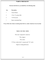
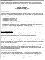
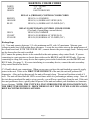
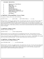
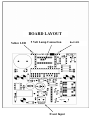
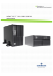
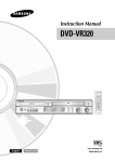
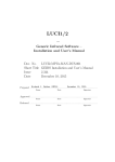
AMERICAN ACCESS SYSTEMS
ADVANTAGE DK
INSTALLATION AND PROGRAMMING INSTRUCTIONS
MODELS
ADV-05(i) thru 1000(i)
Revision D
Please Read Before Using This Equipment
TECHNICAL SUPPORT: 303-799-9757 Monday thru Friday 8:30 a.m. - 5:00 p.m. MST
2 Year Warranty
What item(s) this warranty applies to:
American Access Systems "ADVANTAGE DK" access controls.
What is covered:
Any defect in materials or workmanship.
For how long:
Two years from date of purchase.
What we will do:
If your AAS product is defective and returned within 2 years of the date of purchase, we will repair it or, at our option, replace it at no charge to
you. If we repair your AAS product, we may use new or reconditioned parts. If we choose to replace your AAS product, we may replace it with a
new or reconditioned one of the same or similar design. The repair or replacement will be warranted for (a) 90 days or (b) the remainder of the
original two year warranty period, whichever is longer.
Limitations:
Implied warranties, including those of fitness for a particular purpose and merchant ability (an unwritten warranty that the product is fit for
ordinary use), are limited to two years from date of purchase. We will not pay for loss of time, inconvenience, loss of use of your AAS product,
service calls, or property damage caused by your AAS product or its failure to work, or any other incidental or consequential damages. Some
states do not allow limitations on how long an implied warranty lasts or the exclusion or limitation of incidental or consequential damages, so the
above exclusions or limitations may not apply to you.
What we ask you to do:
To get warranty service for your AAS product, you muse provide proof of the date of purchase. Contact the original dealer or installer of the
product and return your AAS product along with the receipt to them. If you have problems locating the dealer or installer contact American
Access Systems at (303) 799-9757 and we will direct you to an authorized dealer or distributor of American Access Systems products. If you
ship your AAS product, you must prepay all shipping costs. We suggest that you retain your original packing material in the event you need to
ship your AAS product. On return, include your name, address, phone number, proof of date of purchase, and a brief description of the operating
problem.
What this warranty does not cover:
This warranty does not cover defects resulting from accidents, damage while in transit, alterations, unauthorized repair, failure to follow
instructions, misuse, fire, flood, and acts of God. Nor do we warrant your AAS product to be compatible with any particular external device or
peripheral. If your warranty has expired on your AAS product or if your product is NOT covered contact your dealer or installer for advice on
whether we will repair your AAS product and other repair information, including estimated repair costs and other charges. We, at our option,
may replace rather than repair your AAS product with a new or similar design if the damage to the unit is severe or extensive.
This warranty is the only one we give on this product, and it sets forth all our responsibilities regarding your AASproduct. There are no other
express warranties.
State Law rights:
This warranty gives you specific legal rights, and you may also have other rights which vary from state to state.
AMERICAN ACCESS SYSTEMS, INC.
7079 SOUTH JORDAN ROAD / UNIT 6
ENGLEWOOD, CO. 80112
PH: (303) 799-9757
FAX: (303) 799-9756
SERIAL# ______________
Page 1
PARTS CHECKLIST
Enclosed with this box you should have the following items.
Qty
Description
1
Control Station
4
1/4 by 1/2 carriage bolts
4
1/4-20 hex nuts
1
Square mounting flange
If any of the above items are missing from this box, contact American Access Systems
TOOLS YOU WILL NEED
Wire nuts or appropriate connectors
Wire strippers
Wire cutters
3/8" drive ratchet with 6" extension and 7/16" socket
Digital or Analog multi-meter
Page 2
Page 3
BEFORE PROCEEDING
To take full advantage of the 24 month limited warranty, you must register with American Access
Systems, Inc. Please read the enclosed warranty statement, (pg. 1), fill out the warranty registration
card provided, and send it to:
American Access Systems, Inc.
Warranty Registration
7079 South Jordan Road / Unit 6
Englewood, Co. 80155
INTRODUCTION
Your new AAS unit is a high quality, programmable, commercial digital key control station which will
control access to a passageway using 4 digit access codes. The Advantage DK incorporates state of the
art electronics to provide a product which is highly sophisticated yet inexpensive. Your unit
incorporates the following features.
• 1 programmable 4 digit Master Code.
• 1 programmable 4 digit Sleep Code
• 1 programmable 4 digit Latch Code
• Up to 1000, (depending on the model), 4 digit access codes which may be assigned to 1
of 2
relays
• A programmable “three strikes-you’re out” feature which will disable the unit for approximately 1
1/2 minutes if 3 incorrect codes are entered within a 3 minute time period.
• 2 relays programmable from of 1/2 to 99 seconds incorporating both (N/O) and normally closed (N/
C) contacts.
• An external event trigger programmable as a Remote Inactive, Arming, or Remote Open input.
STEP1 (Mounting the unit)
Page 3 states the tools and instruments needed to install your unit as well as a parts check list. Make
sure to have all the tools listed. Upon opening the box, check off the items enclosed with the unit. If
any items are missing from your unit, contact American Access Systems immediately.
Mounting the unit to your own pedestal
Your unit comes with a square mounting flange found in the bottom of the box along with four carriage
bolts and four hex nuts. The square mounting flange may be welded to your pedestal and the flange bolt
pattern will align with the unit. Place the unit up to the flange and insert the four carriage bolts from the
backside. Secure the unit to the flange.
Mounting the unit to an AAS gooseneck pedestal (18-001) or double height gooseneck (18-003)
Locate the four carriage bolts and four hex nuts found inside the unit box. Place the unit up to the
pedestal flange and insert the four carriage bolts from the backside. Secure the unit to the pedestal. The
extra square mounting flange may be discarded.
STEP2 (SYSTEM CONNECTIONS)
Wiring diagrams for your unit are presented on page 3. Usually, you will be interfacing the unit to a
gate operator. However, a wiring diagram for interface to an electric door strike or mag lock is also
provided. Carefully study the diagram which best suits your particular installation . On the following
page, (page 5), are shown the wire harness color codes. After studying, go on to the hookup steps.
Page 4
HARNESS COLOR CODES
WHITE
WHITE
GREEN
11.5 - 29 volts
AC or DC
EARTH GROUND
BROWN
ORANGE
BLUE
RELAY A (PRIMARY) CONTROL COLOR CODES
RELAY (A) COMMON
RELAY (A) NORMALLY OPEN (N/O)
RELAY (A) NORMALLY CLOSED (N/C)
GRAY
VIOLET
YELLOW
RELAY B (SECONDARY) CONTROL COLOR CODES
(Used only if controlling a second device)
RELAY (B) COMMON
RELAY (B) NORMALLY OPEN (N/O)
RELAY (B) NORMALLY CLOSED (N/C)
Hookup Steps
(A). Your unit operates between 11.5 volts minimum and 29 volts AC maximum. Measure your
voltage to make sure it falls within these tolerances. Locate the two white wires on the main harness of
the circuit board and, WITH THE POWER OFF, connect them to the power supply leads. Polarity need
not be observed as the unit is rectified.
(B). Connect the primary device to be controlled to the units primary relay control leads. If you are
connecting to a gate operator or electric door strike use the BROWN and ORANGE leads. If you are
connecting to a mag-lock or any device that requires power in the locked state, use the BROWN and
BLUE leads. (See page 3). If you are interfacing to a secondary device, connect the units secondary
relay control leads to the device.
(C). Double check your connections. When you are sure you have the unit hooked up correctly, apply
power to the unit. If this is the FIRST TIME POWER UP of the unit, the unit will perform self
diagnostics. After each test has passed, the unit will sound a beep. The unit will perform a total of 4
tests. The unit will then flash the LED's several times while it is performing a memory setup. Once all
the tests have passed and the unit is set up correctly, you will hear a good beep from the unit. If the unit
does not perform as above, quickly shut off power to the unit and contact your distributor or American
Access Systmes. NOTE: THE UNIT WILL ONLY PERFORM THE SELF DIAGNOSTICS ON
THE FIRST TIME POWER UP. FROM THERE ON OUT THE UNIT WILL SOUND A GOOD
BEEP EACH TIME POWER IS APPLIED.
Page 5
ACCESS & FUNCTION CODES
Depending on which model you have, your unit may be programmed with multiple (4 digit) access codes, the number of
access codes is reflected in the model number (eg. ADV-15(i) = 15 access codes). There are two different types of codes,
access codes & function codes. Although the number of access codes will vary with each model, the number of function
codes is always 3.
FUNCTION CODES
"MASTER CODE"
This code is a programmable four digit code
used for gaining access to the program mode.
The factory default master code is 1 2 5 1.
"LATCH CODE"
This code is a programmable four digit code
used to toggle relay A. This code will be used
to hold open a gate or door.
"SLEEP CODE"
This code is a programmable four digit code
which when entered, will disable all codes.
When the "SLEEP CODE" is entered again the
unit will be enabled. An override code is provided.
GOODBEEPS & ERRORBEEPS
Your unit will beep each time a key is pressed. The "*" key serves as the clear key and a double beep will be heard when
this key is pressed. A "GOODBEEP" is represented by an oscillating high tone. An "ERROR BEEP" is represented by a
single low tone.
THE RED & YELLOW LED's
Two different colored LED's are in the face of the unit. The red LED will light during the duration of the relay(s)
activation period. The yellow LED will light while the unit is in the program mode. During memory erasure or setup the
LED's will flash.
RESETTING THE UNIT
Your unit provides 2 different types of resets, a Unit Reset, and a Master Reset.
A Master Reset should be utilized in the event that you lose or forget your master code or if the unit is in the Latch or
Sleep mode and the Latch or Sleep code is lost or forgotten. When a Unit Reset is performed, the master code will be set
back to 1 2 5 1.
A Unit Reset is provided should it ever become desirous to reset the unit back to the initial factory state. After a Master
Reset has been performed the unit will DELETE ALL ACCESS & FUNCTION CODES and the master code will be
set back to 1 2 5 1.
MASTER RESET
Follow these steps precisely. If you make an error, the unit will ERROR and you will have to start over.
Disconnect power from the unit by pulling the wire harness away from the board.
Reconnect power to the board while holding down the RESET button (See location diagram, pg. 11 ).
⇒ Release Reset button and enter * * * from the keypad.
⇒
⇒
The unit will issue a good beep and the master code will be set back to 1 2 5 1. If you previously were in the sleep or
latch mode, the unit will be brought back to idle state.
Page 6
UNIT RESET
(!!!!! WARNING: ALL CODES WILL BE DELETED FROM MEMORY !!!!!)
* (Please See pg. 6 for further information)
Follow these steps precisely. If you make an error, the unit will ERROR and you will have to start over.
⇒ Disconnect power from the unit by pulling the wire harness away from the board.
⇒ Reconnect power to the board while holding down the RESET button (See location diagram, pg.
11 ).
⇒ Release Reset button & enter # * # (The unit will respond with a GOOD BEEP)
UNIT RESET
(Please see from
pg. 6 for further
information) (The unit will flash the LED's several times and then
⇒ Enter the MASTER CODE
the keypad.
go into an endless cycle
ofthese
beeps)
Follow
steps precisely. If you make an error, the unit will ERROR and you will have to
start over.
⇒ Disconnect & Reconnect power to the unit. (The unit will go through the "First Time Power Up"
Disconnect power from the unit by pulling the wire harness away from the board.
sequence (See page 5).(1).
(2). Reconnect power to the board while holding down the RESET button (See location
diagram, pg. 11 ).
(3). Release Reset button and enter * *
from the keypad.
The unit will issue a good beep and the master code will be set back to 1 2 5 1. If you
The idle mode
previously were in the sleep or latch mode, the unit will be brought back to idle state.
The idle mode is the normal
mode of operation. When in this mode the unit sits and waits for data from
MASTER RESET
WARNING:
CODES
WILL
BE DELETED FROM MEMORY
!!!!!) between keypresses. If this time
the keypad. When in this(!!!!!
mode
youALL
will
have
approximately
4 seconds
* (Please See pg. 6 for further information)
is exceeded, you will receive
Follow an
theseERROR.
steps precisely. If you make an error, the unit will ERROR and you will have to
start over.
(1). Disconnect power from the unit by pulling the wire harness away from the board.
(2). Reconnect power to the board while holding down the RESET button (See location
diagram, pg. 11 ).
(3). Release Reset button & enter # * # (The unit will respond with a GOOD BEEP)
(4). Enter the MASTER CODE from the keypad. (The unit will flash the LED's several times
and then go into an endless cycle of beeps)
(5). Disconnect & Reconnect power to the unit. (The unit will go through the "First Time
Power Up" sequence (See page 5).
The program mode
The program mode is the mode of operation in which you will enter, delete, or change your codes or set
specific features of the unit. The program mode is accessed by entering the "MASTER CODE" from
the keypad. You will receive a GOOD BEEP and the yellow LED will come on indicating that you are
idlemode
mode
in the program mode. In The
this
you will have approximately 30 seconds between key presses. If
this time is exceeded, youThewill
receive
an mode
ERROR
andWhen
beinexited
from
the
program
mode.
idle mode
is the normal
of operation.
this mode the
unit sits
and waits
for
data from the keypad. When in this mode you will have approximately 4 seconds between
keypresses. If this time is exceeded, you will receive an ERROR.
The program mode
The * and # keys
The program mode is the mode of operation in which you will enter, delete, or change your
The * and # keys serve specific
idle
oris program
mode.
The * key is always the
codes or set functions
specific features while
of the unit.in
Thethe
program
mode
accessed by entering
the
"MASTER CODE" from the keypad. You will receive a GOOD BEEP and the yellow LED
clear key and a double beep
will be heard when depressed. You should use this key if you make an
will come on indicating that you are in the program mode. In this mode you will have
approximately
presses.
this idle
time is exceeded,
receive
an
entry error. The # key also serves30asseconds
the between
clearkeykey
in Ifthe
mode.youInwillthe
program
mode however, it
ERROR and be exited from the program mode.
serves as the exit key and will at any time when depressed, exit you from the program mode.
The * and # keys
The * and # keys serve specific functions while in the idle or program mode. The * key is
always the clear key and a double beep will be heard when depressed. You should use this
key if you make an entry error. The # key also serves as the clear key in the idle mode. In the
program mode however, it serves as the exit key and will at any time when depressed, exit you
from the program mode.
PROGRAMMING
A person desiring access to the program mode will enter the present MASTER CODE. If the master
code is valid the yellow LED will come on and the individual will be prompted with a GOOD BEEP to
enter a number corresponding to a SUB-MODE, (MASTER CODE) + (Number corresoponding
to Sub-Mode). Once in the program mode, the individual will have 30 seconds between keypresses or
the unit will ERROR and exit the program mode. A person desiring to exit the program mode may do
so by simply pressing the # key at any time. There are 10 different SUB-MODES to choose from.
They are as follows:
Page 7
SUB-MODE DESCRIPTION
1
2
3
4
5
6
7
8
9
0
♦
Program Access Codes (Relay A)
Delete Codes
Change Master Code
Set Sleep Code
Set Latch Code
Set Relay Output Times
Program Access Codes (Relay B)
Enable / Disable "3 Strikes-You’re Out"
Program Event Input
Erase Memory
Sub-Mode 1 (Program Relay A Access Codes)
To program new Relay A access codes enter the following;
(MASTER CODE)
+
1
+
(NEW CODE)
+
(NEXT NEW CODE) etc......... ( # to exit)
Should you make a code entry error, simply press the * key and enter the correct code. You may select any 4 digit code
you wish. If you receive an ERROR after entry, you must select another code as it is already in use. The unit will
respond with a GOOD BEEP with the acceptance of each new Relay A code. You may continue entering Relay A codes
until you finish (Press #), or the memory becomes full. You will automatically be exited from the program mode if the
memory reaches capacity. When memory is full you will not be able to enter this Sub-Mode and will receive an ERROR
if entry is attempted.
♦
Sub-Mode 2 (Delete Codes)
To delete codes enter the following;
(MASTER CODE)
+
2
+
(CODE TO BE DELETED)
Should you make an entry error, simply press the * key and enter the correct code. You may delete any access or
function code that you wish with the exception of the MASTER CODE. If the code you wish to delete is not found in
memory, the unit will respond with an ERROR and wait for another code to be entered. A GOOD BEEP will be sounded
once the code has been found and deleted. You may continue deleting codes until you finish (Press #).
♦
Sub-Mode 3 (Change Master Code)
To change your master code enter the following;
(present MASTER CODE)
+
3
+
(new MASTER CODE)
Should you make a code entry error, simply press the * key and enter the correct code. You may select any 4 digit master
code you wish. If you receive an ERROR, you must select another code as it is already in use. The unit will respond
with a GOOD BEEP with the acceptance of the new Master Code and you will be exited from the program mode.
MAKE SURE TO WRITE THE NEW MASTER CODE DOWN.
Page
Page
8 8
♦
Sub-Mode 4 (Set Sleep Code)
EXPLANATION: The sleep code is used to disable all Relay A and function codes from the keypad. This feature is
most commonly used in applications where no entry is desired after hours. Relay B codes will still be valid from the
keypad. By connecting both relays in parallel, managers may be assigned RelayB codes and still gain access. While in
the SLEEP MODE, the yellow and red LED's will flash approximately once every 3 seconds. To initialize the system
back to normal, simply re-enter the sleep code. Should you lose or forget your sleep code and the unit is in the sleep
mode see the Unit Reset instructions on pages 6 & 7.
To program or change your sleep code enter the following;
(MASTER CODE)
+
4
+
(SLEEP CODE)
Should you make a code entry error, simply press the * key and enter the correct code. You may select any 4 digit sleep
code you wish. If you receive an ERROR, you must select another code as it is already in use. The unit will respond
with a GOOD BEEP with the acceptance of the new Sleep Code and you will be exited from the program mode.
♦
Sub-Mode 5 (Set Latch Code)
EXPLANATION: The Latch Code toggles the state of the main relay (A) of the circuit board. The red LED will light if
the relay is in the latched position. The latch code is useful in applications where the gate is desired to hold open. If the
operator's close circuit is controlled by loops, timers, etc., they will be overridden by the latched state of the relay and the
gate will hold open. An "OPEN-OVERRIDE" circuit must exist in the operator in order to utilize this function. If your
gate cycles when this code is entered, your operator is not set up to utilize this function. Your local dealer or distributor
should be able to assist you if you have any specific questions.
To program or change your latch code enter the following;
(MASTER CODE)
+
5
+
(LATCH CODE)
Should you make a code entry error, simply press the * key and enter the correct code. You may select any 4 digit latch
code you wish. If you receive an ERROR, you must select another code as it is already in use. The unit will respond
with a GOOD BEEP with the acceptance of the new Latch Code and you will be exited from the program mode. When
the latch code is entered the RED Led will light and the gate will hold open. When the latch code is entered again the
RED Led will go off and the gate will close. NOTE: On gates with a timer to close the “TIMED DURATION” starts
when the latch code is released.
♦
Sub-Mode 6 (Set Relay Output Times)
To set or change a relay output time enter the following;
(MASTER CODE) + 6 + (RELAY #) + (RELAY OUTPUT TIME) in seconds
The Relay # corresponds to which relay to set. 1 = Relay A, 2 = Relay B. Should you make a code entry error, simply
press the * key and enter the correct code. Your output time is set on both relays from the factory at approximately 1/2
seconds "00". If a longer output time is desired, enter a two digit number corresponding to the number of seconds
between "00" and "99". By entering "00" the output time is set to approximately 1/2 seconds which is ideal for most
operators.
Page 9
♦
Sub-Mode 7 (Program Relay B Access Codes)
To program new Relay B access codes enter the following;
(MASTER CODE)
+
7
+
(NEW CODE)
+
(NEXT NEW CODE) etc......... ( # to exit)
Should you make a code entry error, simply press the * key and enter the correct code. You may select any 4 digit code
you wish. If you receive an ERROR after entry, you must select another code as it is already in use. The unit will
respond with a GOOD BEEP with the acceptance of each new Relay B code. You may continue entering Relay B codes
until you finish (Press #), or the memory becomes full. You will automatically be exited from the program mode if the
memory reaches capacity. When memory is full you will not be able to enter this Sub-Mode and will receive an ERROR
if entry is attempted.
♦
Sub-Mode 8 (Enable/Disable 3 Strikes-You’re Out)
EXPLANATION: This feature is desirable to keep unwanted persons from successively entering codes until they "hit" a
programmed access code. By selecting this function you enable a 1 1/2 minute lock out period if 3 incorrect codes are
entered successively within a 3 minute period. When this occurs, the LED's will flash and a high pitched alarm will be
generated from the unit for 30 seconds. The unit will then shutdown for 1 minute.
To toggle the 3 strikes-you’re out feature enter the following;
(MASTER CODE)
+
8 (*current state)
+
(MASTER CODE)
*current state
single beep = 3 strikes enabled
double beep = 3 strikes disabled
Should you make a code entry error, simply press the * key and enter the correct code. After you have selected mode 8,
the unit will respond with a single or double beep. A single beep indicates that the 3 strikes-you’re out feature is
presently enabled. A double beep indicates that the 3 strikes-you’re out feature is presently disabled. The unit will then
issue a GOOD BEEP and wait for the master code. If you wish to toggle the 3 strikes your out state, enter the master
code. If you do not wish to toggle the state, enter # to exit.
♦
Sub-Mode 9 (Program Event Input)
EXPLANATION: The event input allows the user to tie in an external device to control specific functions of the unit.
The event input can be programmed in 1 of 4 ways:
• REMOTE INACTIVE: Relay A codes may be made inactive by an external switch. When inactive all relay A codes
will be disabled. The relay B, program, and function codes will still be accessible to the end user.
• ARMING CIRCUIT: This is normally used to allow access in parking situations. An external vehicle detector may
be connected to the input. Relay A codes would only become active on the prescence detect of a vehicle. If an entry
attempt to activate relay A is made while the input is not activate, entry will be denied. The relay B, program, and
function codes will still be accessible to the end user.
• REMOTE OPEN: A relay may be activated using a pushbutton or switch. The relay to activate is user selectable.
This function operates even when the unit is in sleep, latch, or program mode.
• DISABLE: Disables the Event Input.
Page 10
◊
To program the event input as Remote Inactive enter the following;
(MASTER CODE) + 9 (*current mode) + 1
◊
To program the event input as an Arming Circuit enter the following;
(MASTER CODE) + 9 (*current mode) + 2
◊
To program the event input as Remote Open enter the following;
(MASTER CODE) + 9 (*current mode) + 3 + (*Relay to Activate)
◊
To DISABLE the event input enter the following;
(MASTER CODE) + 9 (*current mode) + 0
*Current Mode
Single beep = Remote Inactive Mode Enabled.
Double beep = Arming Circuit Mode Enabled.
Triple beep = Remote Open Mode Enabled.
GoodBeep Only = Event Input Disabled.
*Relay to Activate
1 = Relay A.
2 = Relay B.
After you have selected mode 9, the unit will respond with tones as described above. This gives the
current mode the event input is programmed as (See *Current Mode above). If you do not wish to
toggle the state, enter # to exit. If you are programming the event input as a Remote Open input, you
will be prompted for which relay to activate on an event. Enter the correct relay as stated above (*Relay
to Activate).
♦
Sub-Mode 0 (Erase all codes)
To erase all access & function codes, (except the master code), enter the following;
(MASTER CODE) + 0 + (MASTER CODE)
Should you make a code entry error, simply press the * key and enter the correct code. When the
sequence is entered correctly, the LED's will flash serveral times and the unit will generate a GOOD
BEEP when it has finished clearing the memory. If the above sequence is not validated by the unit you
will receive an ERROR and immediately be exited from the program mode.
AN IMPORTANT NOTE: It should not generally be necessary to erase all the codes from
memory unless codes are
forgotten
and are occupying necessary memory. A good log and
Page
11
maintenance of access codes should prevent this from ever needing to be done.
Page 11
BOARD LAYOUT
Yellow LED
5 Volt Lamp Connection
pagePage
12 12
Event Input
Red LED
Notes
Page 13
Notes
Page 14
American Access Systems
Inc.
7079 South Jordan Road #6
Englewood, Co. 80112
Sales: 1-800 541-5677
E-mail: [email protected]
Customer Service: 1-303-799-9757
E-mail: [email protected]
Tech-Support: 1-303-799-9757
E-mail: [email protected]
01B6950F88