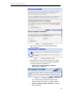
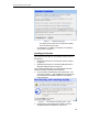
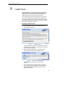
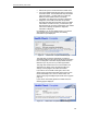
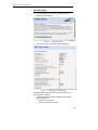
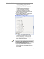
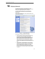
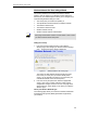
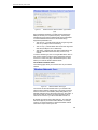
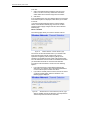
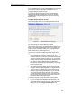
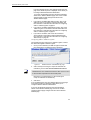
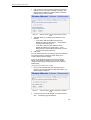
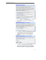
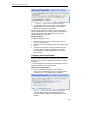
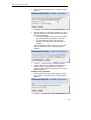
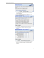
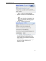
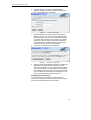
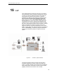
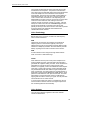
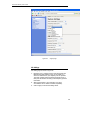
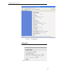
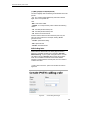
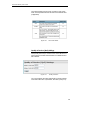
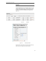
Download Multitek Comm-Box User`s guide
Transcript
ADSL/VoIP Gateway User’s Guide Comm--Box Comm ADSL/VOIP Gateway User’s Manual 1 ADSL/VoIP Gateway User’s Guide Comm-Box ADSL/VOIP Gateway INSTALLATION & USER MANUAL Thank you for choosing the Comm-Box ADSL/VOIP gateway. This manual teaches the features of your gateway. So you may get the best performance from your exchange for years without having any trouble. Please note that the product , its specification and the information appearing in this document are subject to change by Multitek without notice. Multitek Elektronik San.Tic.Ltd. www.multitek.com.tr [email protected] Issue 1.2 COMM-BOX.DOC-1.2- 010107 2 ADSL/VoIP Gateway User’s Guide Table of Contents 1 Introduction ........................................................ 10 Features................................................................................ 10 Device Requirements .......................................................... 10 Using this Document............................................................ 12 Notational conventions ................................................. 12 Typographical conventions .......................................... 12 Special messages......................................................... 12 Getting Support .................................................................... 12 2 Getting to know the device................................ 13 Parts Check .......................................................................... 13 Front Panel ........................................................................... 14 Rear Panel............................................................................ 14 3 Connecting your device..................................... 16 Connecting the Hardware.................................................... 16 Step 1. Connect the DSL cable and optional telephone line ............................................................ 17 Step 2. Connect the Ethernet cable............................. 17 Step 3. Attach the power connector ............................ 17 Step 4. Configure your Ethernet PCs .......................... 17 Step 5. Install a Wireless card and connect Wireless PCs ............................................................. 17 Next step........................................................................ 18 4 Getting Started with the Web pages................. 19 Accessing the Web pages................................................... 19 Web page menu overview................................................... 20 Commonly used buttons...................................................... 21 Help information ................................................................... 22 Testing your Setup............................................................... 22 Default device settings......................................................... 23 5 Current Status ................................................... 24 Internet access settings ....................................................... 24 About Productname ............................................................ 25 6 Firmware Update............................................... 26 About firmware versions ...................................................... 26 3 ADSL/VoIP Gateway User’s Guide Checking for firmware updates ........................................... 26 Updating your firmware ....................................................... 28 Manually updating firmware ................................................ 29 7 Health Check ..................................................... 31 Running the Health Check .................................................. 31 DSL Status page .................................................................. 33 8 Help.................................................................... 38 Using the Help page ............................................................ 38 About the Online User Guide .............................................. 39 9 Addressing......................................................... 40 Changing the LAN IP address and subnet mask .............. 40 10 Wireless Network .............................................. 42 Wireless Network First Time Settings Wizard.................... 43 Setting the Country ....................................................... 43 Select your Wireless Network Type ............................ 43 Set the Wireless Network Name.................................. 44 Select a Channel........................................................... 45 Configure Wireless Network Security.......................... 46 Configuring 64bit or 128bit encryption......................... 47 Configuring WPA security ............................................ 48 Configure Wireless Address Authentication ............... 48 Configuring the wireless PC blacklist .......................... 49 Configuring the wireless PC whitelist .......................... 50 Confirm Wireless network changes............................. 51 Wireless Network General Settings.................................... 52 Enabling/disabling wireless networking....................... 53 Displaying details of Wireless PCs .............................. 53 11 Advanced Security ............................................ 55 Configuring NAT Security.................................................... 55 Assigning PC Names........................................................... 56 Deleting PC Names ...................................................... 58 Configuring Internet applications ........................................ 58 Enabling Internet applications ...................................... 58 Disabling Internet applications ..................................... 59 Configuring custom applications ......................................... 60 Creating custom applications ....................................... 60 4 ADSL/VoIP Gateway User’s Guide Deleting custom applications ....................................... 62 12 Internet Access.................................................. 63 Types of Internet Access ..................................................... 63 Configuring Automatic Internet Access .............................. 64 Configuring your PPP DSL connection .............................. 65 Enabling MAC spoofing................................................ 68 Editing your existing MAC spoofing settings............... 69 Configuring your DHCP DSL connection ........................... 70 Configuring your Internet Access manually ....................... 71 13 Password........................................................... 74 Setting your username and password................................ 74 Disabling password protection ..................................... 75 14 Reset to Defaults............................................... 76 Resetting to Defaults............................................................ 76 15 VoIP ................................................................... 78 Voice Terminology ............................................................... 79 Voice features....................................................................... 79 Telephony data processing features .................................. 80 VoIP Configuration............................................................... 80 System Settings ................................................................... 81 SIP Settings.......................................................................... 82 Dialling Plan.......................................................................... 83 PSTN Calling Rules ............................................................. 85 Quality of Service (QoS) Settings ....................................... 86 Endpoints.............................................................................. 87 A Configuring your Computers............................. 88 Configuring Ethernet PCs.................................................... 88 Before you begin........................................................... 88 Windows® XP PCs....................................................... 88 Windows 2000 PCs ...................................................... 89 Windows Me PCs ......................................................... 90 Windows 95, 98 PCs .................................................... 90 Windows NT 4.0 workstations ..................................... 91 Assigning static Internet information to your PCs............................................................................. 92 Configuring Wireless PCs ................................................... 95 Positioning the wireless PCs........................................ 95 5 ADSL/VoIP Gateway User’s Guide Wireless PC cards and drivers..................................... 95 Configuring PC access to your Wireless device......... 95 B IP Addresses, Network Masks, and Subnets........................................................... 97 IP Addresses ........................................................................ 97 Structure of an IP address............................................ 97 Network classes ............................................................ 98 Subnet masks....................................................................... 98 C Troubleshooting............................................... 100 Troubleshooting Suggestions ...........................................100 Diagnosing Problem using IP Utilities...............................102 ping ..............................................................................102 nslookup ......................................................................102 D Advanced DSL port attributes......................... 104 E Glossary........................................................... 109 Index 117 6 ADSL/VoIP Gateway User’s Guide Table of Figures Figure 1: ADSL/VoIP Gateway ................................................................................. 13 Figure 2: Front Panel and LEDs ............................................................................... 14 Figure 3: Rear Panel Connections ........................................................................... 15 Figure 4: Overview of Hardware Connections......................................................... 17 Figure 5: Login screen ............................................................................................... 19 Figure 6: The Welcome page.................................................................................... 20 Figure 7: Current Status page................................................................................... 24 Figure 8: Firmware Update page.............................................................................. 27 Figure 9: Checking for Updates… page................................................................... 27 Figure 10: No updates available page........................................................................ 27 Figure 11: Update Available page .............................................................................. 28 Figure 12: Downloading and installing update… page ............................................. 28 Figure 13: Update Installed page................................................................................ 29 Figure 14: Restarting page.......................................................................................... 29 Figure 15: Manual Update Installation section........................................................... 29 Figure 16: Health Check page .................................................................................... 31 Figure 17: Health Check: Running page .................................................................... 31 Figure 18: Health Check: Complete with failures page............................................. 32 Figure 19: Health Check: Complete with no failures page........................................ 32 Figure 20: Health Check page .................................................................................... 33 Figure 21: Health Check: DSL Status page............................................................... 33 Figure 22: DSL Port Basic Configuration page.......................................................... 34 Figure 23: Port A1 Advanced Configuration page (part 1)........................................ 35 Figure 24: Port A1 Advanced Configuration page (part 2)........................................ 36 Figure 25: Help page Figure 26: Help – Close link ........................................................................................ 39 Figure 27: Addressing page ........................................................................................ 40 Figure 28: Addressing: Setup page ............................................................................ 40 Figure 29: Addressing: Confirm page......................................................................... 41 Figure 30: Wireless Network page.............................................................................. 42 Figure 31: Wireless Network: Set Country page ....................................................... 43 Figure 32: Wireless Network: Wireless Network Type Selection page.................... 44 Figure 33: Wireless Network: Basic page .................................................................. 44 Figure 34: Wireless Network: Channel Selection page............................................. 45 ............................................................................................... 38 7 ADSL/VoIP Gateway User’s Guide Figure 35: Wireless Network: Channel Selection (manual) page............................ 45 Figure 36: Wireless Network: Security page.............................................................. 46 Figure 37: Wireless Network: 128bit Network Key page........................................... 47 Figure 38: Wireless Network: Wi-Fi Protected Access page .................................... 48 Figure 39: Wireless Network: Address Authentication page .................................... 48 Figure 40: Wireless Network: Address Authentication (blacklist) page.................... 49 Figure 41: Wireless Network: Address Authentication (blacklist) page.................... 49 Figure 42: Wireless Network: Address Authentication (blacklist) page.................... 50 Figure 43: Wireless Network: Address Authentication (whitelist) page.................... 50 Figure 44: Wireless Network: Address Authentication (whitelist) page.................... 51 Figure 45: Wireless Network: Address Authentication (whitelist configuration) page .................................................................................... 51 Figure 46: Wireless Network: Confirm page .............................................................. 52 Figure 47: Wireless Network: General Settings section............................................ 52 Figure 48: Wireless Network: Enable/Disable page.................................................. 53 Figure 49: Wireless Network: Connected Wireless PCs page ................................. 54 Figure 50: Advanced Security page ........................................................................... 57 Figure 51: Advanced Security: PC Names page....................................................... 57 Figure 52: Advanced Security: Add PC Name page................................................. 57 Figure 53: Advanced Security: Add PC Name page................................................. 58 Figure 54: Advanced Security: Enabled Applications page...................................... 58 Figure 55: Advanced Security: Enable Application page.......................................... 59 Figure 56: Advanced Security: Confirm Application page ........................................ 59 Figure 57: Advanced Security: Disable Application page ......................................... 59 Figure 58: Advanced Security: Custom Applications page....................................... 60 Figure 59: Advanced Security: Create Application page .......................................... 61 Figure 60: Advanced Security: Add Port page........................................................... 61 Figure 61: Advanced Security: Confirm Custom Application page .......................... 61 Figure 62: Advanced Security: Disable Application................................................... 62 Figure 63: Internet Access page ................................................................................. 64 Figure 64: Internet Access: Types of Access page ................................................... 64 Figure 65: Internet Access: Auto page ....................................................................... 64 Figure 66: Internet Access: Searching page.............................................................. 65 Figure 67: Internet Access: PPP Setup page ............................................................ 65 Figure 68: Internet Access: Search Complete page ................................................. 65 Figure 69: Internet Access page ................................................................................. 66 Figure 70: Internet Access: Types of Access page ................................................... 66 8 ADSL/VoIP Gateway User’s Guide Figure 71: Internet Access: PPPoA page................................................................... 67 Figure 72: Internet Access: VPI and VCI Setup page ............................................... 67 Figure 73: Internet Access: Confirm page.................................................................. 67 Figure 74: Internet Access: PPPoE page................................................................... 68 Figure 75: Internet Access: MAC Spoofing page ...................................................... 69 Figure 76: Internet Access: MAC Spoofing Setup page ........................................... 69 Figure 77: Internet Access: MAC Spoofing Confirm ................................................. 69 Figure 78: Internet Access page ................................................................................. 70 Figure 79: Internet Access: Types of Access page ................................................... 70 Figure 80: Internet Access: VPI and VCI Setup page ............................................... 71 Figure 81: Internet Access: Confirm page.................................................................. 71 Figure 82: Internet Access page ................................................................................. 72 Figure 83: Internet Access: Types of Access page ................................................... 72 Figure 84: Internet Access: Manual Setup page ....................................................... 72 Figure 85: Internet Access: VPI and VCI Setup page ............................................... 73 Figure 86: Internet Access: Confirm page.................................................................. 73 Figure 87: Password page .......................................................................................... 74 Figure 88: Password: Enable/Disable page............................................................... 74 Figure 89: Password: Setup page .............................................................................. 75 Figure 90: Password: Confirm page........................................................................... 75 Figure 91: Reset to Defaults page .............................................................................. 76 Figure 92: Resetting to Defaults… page .................................................................... 76 Figure 93: Comm-Box System Interfaces ................................................................. 78 Figure 94: VOIP Page ............................................................................................... 81 Figure 95: Region page ............................................................................................... 82 Figure 96: SIP Setting Page........................................................................................ 83 Figure 97: Dialling Plan ............................................................................................... 83 Figure 98: Special Dialling Codes............................................................................... 84 Figure 99: PSTN Calling Rule Pages ......................................................................... 85 Figure 100: PSTN rules details ..................................................................................... 86 Figure 101: . Quality of Service..................................................................................... 86 Figure 102: Endpoints Figure 103: Edit Endpoints Detail ................................................................................. 87 Figure 104: Using the ping Utility ................................................................................102 Figure 105: Using the nslookup Utility ........................................................................103 ............................................................................................... 87 9 ADSL/VoIP Gateway User’s Guide 1 Introduction Congratulations on becoming the owner of the Multitek CommBox. You will now be able to access the Internet using your highspeed DSL connection. This User Guide will show you how to connect your ADSL/VOIP Gateway, and how to customize its configuration to get the most out of your new product. Features The list below contains the main features of the device and may be useful to users with knowledge of networking protocols. If you are not an experienced user, the chapters throughout this guide will provide you with enough information to get the most out of your device. Features include: • Internal DSL modem for high-speed Internet access • 10/100Base-T Ethernet router to provide Internet connectivity to all computers on your LAN • Wireless access via a wireless network card and wireless security features • Network address translation (NAT) functions to provide security for your LAN • Network configuration through DHCP Server and DHCP Client • Services including IP route and DNS configuration, RIP, and IP and DSL performance monitoring • User-friendly configuration program accessed via a web browser • SIP Privacy Support enables you to make anonymous outgoing calls • SIP Security Negotiation support allows a SIP entity to negotiate the type of security it will be using • SIP Message Waiting Indicator message waiting indication support • SIP TEL-URI Support provided for both local and global forms of Tel-URIs • 3 Way Conferencing enables the endpoint to initiate 3 party conferencing Device Requirements In order to use the ADSL/VOIP Gateway, you must have the following: • DSL service up and running on your telephone line 10 ADSL/VoIP Gateway User’s Guide Note • Instructions from your ISP on what type of Internet access you will be using, and the addresses needed to set up access • One or more computers each containing an Ethernet card (10Base-T/100Base-T network interface card (NIC)) and/or a single computer / One or more computers with wireless network cards • For system configuration using the supplied web-based program: a web browser such as Internet Explorer v4 or later, or Netscape v4 or later. Note that version 4 of each browser is the minimum version requirement – for optimum display quality, use Internet Explorer v5, or Netscape v6.1 You do not need to use a hub or switch in order to connect more than one Ethernet PC to your device. Instead, you can connect up to four Ethernet PCs directly to your device using the ports labeled Ethernet on the rear panel. 11 ADSL/VoIP Gateway User’s Guide Using this Document Notational conventions • Acronyms are defined the first time they appear in the text and also in the glossary. • For brevity, the Hata! Stil tanımlanmamış. is referred to as “the device”. • The term LAN refers to a group of Ethernet-connected computers at one site. • The term WLAN refers to a group of Wireless-connected computers at one site. Typographical conventions • Italic text is used for items you select from menus and dropdown lists and the names of displayed web pages. • Bold text is used for text strings that you type when prompted by the program, and to emphasize important points. Special messages This document uses the following icons to draw your attention to specific instructions or explanations. Note Definition Provides clarifying or non-essential information on the current topic. Explains terms or acronyms that may be unfamiliar to many readers. These terms are also included in the Glossary. Provides messages of high importance, including messages relating to personal safety or system integrity. WARNING Getting Support Multitek Ltd. e-mail : [email protected] Web : www.multitek.com.tr 12 ADSL/VoIP Gateway User’s Guide 2 Getting to know the device Parts Check In addition to this document, your package should arrive containing the following: • ADSL/VOIP Gateway • 12V/2A Power adapter and power cord • Ethernet cable (2 meter long with two sides RJ45 jacks ) • Standard phone/DSL line cable(2 meter long with two sides RJ11 jacks) Figure 1: ADSL/VoIP Gateway 13 ADSL/VoIP Gateway User’s Guide Front Panel The front panel contains lights called Light Emitting Diodes (LEDs) that indicate the status of the unit. Figure 2: Front Panel LEDs (from left to right in order) Label Color Function POWER red On: device is powered on Off: device is powered off INTERNET red On: Valid IP address obtained Off: No IP address obtained Blink: Valid IP packet being transferred ADSL green On: DSL link reaches showtime, which means that your device has successfully connected to your ISP’s DSL network. Off: DSL link not in showtime, your device has not successfully connected to your ISP’s DSL network. Blink: Data being transmitted VOIP green On: VoIP connection is active Off: No VoIP connection Wi-Fi green On: Wireless LAN link established Off: No Wireless LAN link Blink: Data being transmitted LAN 4 (DMZ port) green On: LAN link established and active Off: No LAN link LAN 3 green On: LAN link established and active Off: No LAN link LAN 2 green On: LAN link established and active Off: No LAN link LAN 1 green On: LAN link established and active Off: No LAN link Rear Panel The rear panel contains the ports for the unit's data and power connections. 14 ADSL/VoIP Gateway User’s Guide Figure 3: Rear Panel Connections Label Function Power Connects to the supplied power cable Ethernet 1-4 Connects the device via Ethernet to up to four PCs on your LAN (default) FXS1 – FXS2 Connects the telephones ADSL/FXO Connects the device to a telephone port in the wall of your home/office for DSL communication 15 ADSL/VoIP Gateway User’s Guide 3 Connecting your device This chapter provides basic instructions for connecting the ADSL/VoIP Gateway to a computer or LAN and to the Internet. In addition to configuring the device, you need to configure the Internet properties of your computer(s).. For more details, see the following sections: • Configuring Ethernet PCs on page 88 • Configuring Wireless PCs on page 95 This chapter assumes that you have already established a DSL service with your Internet service provider (ISP). These instructions provide a basic configuration that should be compatible with your home or small office network setup. Refer to the subsequent chapters for additional configuration instructions. Connecting the Hardware This section describes how to connect the device to the wall phone port, the power outlet and your computer(s) or network. WARNING Before you begin, turn the power off for all devices. These include your computer(s), your LAN hub/switch (if applicable), and the ADSL/VoIP Gateway. The diagram below illustrates the hardware connections. The layout of the ports on your device may vary from the layout shown. Refer to the steps that follow for specific instructions. 16 ADSL/VoIP Gateway User’s Guide 5 Wireless PCs 4 Power ADSL/Ethernet Bridge/Router Ethernet Ports FXS FXS ADSL FXO 1 AC adapter Wall phone port Networked Computers Telephone Telephone Figure 4: Overview of Hardware Connections Step 1. Connect the DSL cable and optional telephone line Connect one end of the provided phone cable to the port labeled DSL on the rear panel of the device. Connect the other end to your wall phone port. Step 2. Connect the Ethernet cable Connect either a LAN hub or up to four single Ethernet computers directly to the device via Ethernet cable(s). Note that the cables do not need to be crossover cables. Step 3. Attach the power connector Connect the AC power adapter to the Power connector on the back of the device and plug the adapter into a wall outlet or power strip. Turn on and boot up your computer(s) and any LAN devices such as hubs or switches. Step 4. Configure your Ethernet PCs You must also configure the Internet properties on your Ethernet PCs. See Configuring Ethernet PCs on page 88. Step 5. Connect Wireless PCs Only include this step if your product supports the use of wireless. Your device provides a wireless network card for a Wireless LAN connection (see Front Panel LEDs). 17 ADSL/VoIP Gateway User’s Guide You must configure your Wireless computer(s) in order to access your device. For complete instructions, see Configuring Wireless PCs on page 42. Next step After setting up and configuring the device and PCs, you can log on to the device by following the instructions in Getting Started with the Web pages on page 19. The chapter includes a section called Testing your Setup on page 22, which enables you to verify that the device is working properly. 18 ADSL/VoIP Gateway User’s Guide 4 Getting Started with the Web pages The DSL Modem includes a series of Web pages that provide an interface to the software installed on the device. It enables you to configure the device settings to meet the needs of your network. You can access it through your web browser from any PC connected to the device via the LAN or WLAN Accessing the Web pages To access the Web pages, you need the following: A PC or laptop connected to the LAN or WLAN port on the device. 1. A web browser installed on the PC. The minimum browser version requirement is Internet Explorer v4 or Netscape v4. For the best display quality, use latest version of Internet Explorer, Netscape or Mozilla Firefox.From any of the LAN computers, launch your web browser, type the following URL in the web address (or location) box, and press [Enter] on your keyboard: http://192.168.1.1 • A login screen is displayed: Figure 5: Login screen 2. Enter your user name and password. The first time you log into the program, use these defaults: Note User Name: admin Password: admin You can change the password at any time or you can configure your device so that you do not need to enter a password. See Password on page 74. 3. Click OK. The Welcome page is displayed: 19 ADSL/VoIP Gateway User’s Guide Figure 6: The Welcome page This is the first page displayed each time you log in to the Web pages (see Accessing the Web pages on page 19). This page contains links to the following pages: Note • Addressing; links to the Addressing page that controls your device’s network address. See Addressing on page 40. • Internet Access; links to the Internet Access page that controls how your device connects to the Internet. See Internet Access on page 63. • Wireless Network; links to the Wireless Network page that controls how your wireless PCs connect to your device. See Wireless Network on page 42. If you receive an error message or the Welcome page is not displayed, see Troubleshooting Suggestions on page 100. Web page menu overview The web pages provide information that allows you to configure your device. These pages are listed in the menu on the lefthand side of the screen. Click on an individual menu entry to display a page. Notice that the menu is split into two separate lists. The first list contains entries that display general information about the device including links to the pages that you are most likely to want to 20 ADSL/VoIP Gateway User’s Guide use: • Welcome; see Accessing the Web pages on page 19 • Current Status; see Current Status on page 24 • Firmware Update; see Check for Updates on page 26 • Health Check; see Health Check on page 31 • Help; see Help on page 38 The Setup list contains entries that allow you to change the default settings on your device using a series of Web pages. If you are a typical user, you will not need to make significant changes to the default configuration. • Addressing; see Addressing on page 40 • Wireless Network; see Wireless Network on page 42 • Advanced Security; see Security on page 55 • Internet Access; see Internet Access on page 63 • Password; see Password on page 74 • Reset to Defaults; see Reset to Defaults on page 76 Commonly used buttons The following buttons are used throughout the web pages: Button Function You may need to configure the default settings on more than one Web page. Click on this button once you have changed the configuration on your current page and are ready to move on to the next. This button appears on every configuration page. Click on this button if at any time you decide that you do not want to change the existing settings. This button appears on the final page of a series of configuration pages. Click on this button to confirm that you are happy with the changes that you have made and want to save them. Radio buttons – these appear on many configuration pages. You will be asked to select one radio button from the selection of two or more available. You cannot select more than one radio button at a time. The following terms are used throughout this guide in association with these buttons: • Click – point the mouse arrow over the button, menu entry or link on the screen and click the left mouse button. This performs an action, such as displaying a new page. 21 ADSL/VoIP Gateway User’s Guide • Select – usually used when describing which radio button to select from a list, or which entry to select from a drop-down list. Point the mouse arrow over the entry and left-click to select it. This does not perform an action – you will also be required to click on a button, menu entry or link in order to proceed. Help information In addition to these buttons, you will also see the information icon throughout the Web pages. The information icon is followed by a link (called a hyperlink) to another web page. Click on the hyperlink to display further information about a specific configuration setting. For example, at the Current Status page, clicking on the following hyperlink: displays further information about the details displayed on the Current Status page. If you want to display an index of the Help information available for all web pages, see Help on page 38. Testing your Setup Once you have connected your hardware and configured your PCs, any computer on your LAN should be able to use the device’s DSL connection to access the Internet. To test the connection, turn on the device, wait for 30 seconds and then verify that the LEDs are illuminated as follows: LED Table 1. LED Indicators Behavior Power Solid red to indicate that the device is turned on. If this light is not on, check the power cable attachment. Internet Flashing on/off while data is being transferred. Solid red when a valid IP address has been assigned to the device by the ISP. W-LAN LINK/Act Solid green to indicate that the Wireless LAN connection is operational. LINK/Act LAN Flashing on/off while the device is booting. After about 1015 seconds, solid green to indicate that the device can communicate with your LAN. LINK/Act DSL Flashing on/off while data is being transmitted. Solid green to indicate that the device has successfully established a connection with your ISP. LINK/Act DSL Flashing when the device is sending or receiving data from the Internet. It may be unlit, flashing, or appear solid depending on the current activity. If the LEDs illuminate as expected, test your Internet connection from a LAN computer. To do this, open your web browser, and type the URL of any external website (such as http://www.multitek.com.tr ). The LED labeled LINK/Act DSL should blink rapidly and then appear solid as the device connects to the site. 22 ADSL/VoIP Gateway User’s Guide If the LEDs do not illuminate as expected, you may need to configure your Internet access settings using the information provided by your ISP. For details, see Internet Access on page 63. If the LEDs still do not illuminate as expected or the web page is not displayed, see Troubleshooting Suggestions on page 100 or contact your ISP for assistance. Default device settings In addition to handling the DSL connection to your ISP, the ADSL/VoIP Gateway can provide a variety of services to your network. The device is preconfigured with default settings for use with a typical home or small office network. The table below lists some of the most important default settings; these and other features are described fully in the subsequent chapters. If you are familiar with network configuration, review these settings to verify that they meet the needs of your network. Follow the instructions to change them if necessary. If you are unfamiliar with these settings, try using the device without modification, or contact your ISP for assistance. We strongly recommend that you contact your ISP prior to changing the default configuration. WARNING Option DSL Port IP Address Default Setting Unnumbered interface: 192.168.1.1 Subnet mask: 255.255.255.255 LAN Port IP Address Assigned static IP address: 192.168.1.1 Subnet mask: 255.255.255.0 Explanation/Instructions This is the temporary public IP address of the WAN port on the device. It is an unnumbered interface that is replaced as soon as your ISP assigns a ‘real’ IP address. See Internet Access on page 63. This is the IP address of the LAN port on the device. The LAN port connects the device to your Ethernet network. Typically, you will not need to change this address. See Addressing on page 40. DHCP (Dynamic Host Configuration Protocol) DHCP server enabled with the following pool of addresses: 192.168.1.2 through 192.168.1.20 The Hata! Stil tanımlanmamış. maintains a pool of private IP addresses for dynamic assignment to your LAN computers. To use this service, you must have set up your computers to accept IP information dynamically, as described in Configuring Ethernet PCs on page 89. NAT (Network Address Translation) NAT enabled Your computers’ private IP addresses (see DHCP above) will be translated to your public IP address whenever the PCs access the Internet. See Security on page 55. 23 ADSL/VoIP Gateway User’s Guide 5 Current Status The Current Status page displays useful information about the setup of your device, including: • details of the device’s Internet access settings • version information about your device To display this page: From the left-hand menu, click on Current Status. The following page is displayed: Figure 7: Current Status page The information displayed on this page is explained in detail in the following sections. Internet access settings This section displays details of the settings that allow your device to access the Internet. These details include: IP address and subnet mask: The IP address and subnet mask assigned to your WAN interface. This address is used temporarily until your ISP assigns a real IP address (via DHCP or PPP – see Internet Access on page 63). Default gateway: The address of the ISP server through which your Internet connection will be routed. DNS servers: The Domain Name System (DNS) servers used by your ISP to map domain names to IP addresses. Your ISP assigns all of these settings. In most cases, you will not need to make changes to these settings in order for your 24 ADSL/VoIP Gateway User’s Guide Internet connection to work. If your ISP does ask you to change any of these settings, follow the instructions for manually configuring your device in Internet Access on page 63. About Productname This section displays details of your device’s hardware and firmware versions. If you need to contact your ISP’s support team, they may need to know which hardware/firmware versions you are using in order to answer your query. Your hardware version details contain information about the make and model of your device and its exact hardware components. Your firmware version details contain information about the software program running on your device. From time to time, Multitek may update or add new features to this firmware. They then make the latest updated version available to you via the Internet. For details of how to update your firmware, see Check for Updates on page 26. 25 ADSL/VoIP Gateway User’s Guide 6 Firmware Update The Firmware Update page allows you to: • check if an updated firmware version is available from . See Checking for firmware updates on page 26. • download an updated firmware version and install it on your device. See Updating your firmware on page 28. • manually download the latest firmware version from ’s website and manually update your firmware. See Manually updating firmware on page 29. About firmware versions Firmware is a software program. It is stored as read-only memory on your device. Multitek is continually improving this firmware by adding new features to it, and these features are saved in later versions of the firmware. Your device can check whether there are later firmware versions available. If there is a later version, you can download it via the Internet and install it on your device. Note If there is a firmware update available you are strongly advised to install it on your device to ensure that you take full advantage of any new feature developments. In order to check and download firmware, your device must be attached to the Internet. To check this, see Testing your Setup on page 22. Checking for firmware updates 1. From the left-hand menu, click on Firmware Update. The following page is displayed: 26 ADSL/VoIP Gateway User’s Guide Figure 8: Firmware Update page 2. Click Check for Updates>. The Checking for Updates… page is displayed: Figure 9: Checking for Updates… page 3. This page tells you that a check for updates is in progress. Once the check is complete, the page displayed depends on whether updates are available or not. • If there are no firmware updates available the following page is displayed: Figure 10: No updates available page This confirms that you are already using the latest firmware version and there are no updates available. • If there are firmware updates available, the following page is displayed: 27 ADSL/VoIP Gateway User’s Guide Figure 11: Update Available page The page includes a summary of the firmware update, and a link to the release notes. For instructions on updating your firmware, see Updating your firmware on page 28. Updating your firmware This section assumes that you have already carried out one of the following: • followed the instructions in Checking for firmware updates on page 26. • followed the instructions on manually updating firmware in Manually updating firmware on page 29. If the Updates Available page has confirmed that a firmware update is available, follow the instructions below. 1. From the Update Available page, click Update Now>. The Checking for Updates… page is displayed. Once the device has connected to the firmware update site, the following page is displayed: Figure 12: Downloading and installing update… page 2. The page tells you that the firmware update is currently being downloaded and installed on your device. 28 ADSL/VoIP Gateway User’s Guide Once installation is complete, the following page is displayed: Figure 13: Update Installed page 3. You must restart your device in order to make the device aware that a new firmware version has been installed. To do this, click Restart Productname. The following page is displayed: Figure 14: Restarting page The page tells you that your device is currently being restarted. Once complete, the Current Status page is displayed. See the Current Status on page 24. Manually updating firmware You can manually download the latest firmware version from ’s website to your PC’s file directory. Click on the Multitek link. www.multitekarge.com Once you have downloaded the latest firmware version to your PC, you can manually select and install it as follows: 1. Click on the Browse… button. Figure 15: Manual Update Installation section (Note that if you are using certain browsers (such as Opera 7) the Browse button is labeled Choose.) Use the Choose file box to navigate to the relevant directory where the firmware version is saved. 29 ADSL/VoIP Gateway User’s Guide 2. Once you have selected the file to be installed, click Open. The file’s directory path is displayed in the Update file: text box. 3. Click Update Now>. The device checks that the selected file contains an updated version of firmware. Now follow the instructions from Checking for firmware updates, step 3 on page 27. 30 ADSL/VoIP Gateway User’s Guide 7 Health Check This page allows you to run a health check to test whether the Internet connection on your device is working properly. The health check runs a number of tests in order to diagnose any ‘health’ problems with your device’s Internet access. If you need to contact your ISP’s support team, they may ask you to run the Health Check and describe the results to them. This page also provides you with a link to the DSL Status page, which displays detailed information about your DSL connection. See the DSL Status page on page 33. Running the Health Check 1. From the left-hand menu, click on Health Check. The following page is displayed: Figure 16: Health Check page This page asks you to ensure that your device is connected to your phone line. See Step 1. Connect the DSL cable and optional telephone on page 17. 2. Click on Perform Health Check>. The following page confirms that the health check is currently running: Figure 17: Health Check: Running page The Health Check may take up to three minutes to complete. 3. Once the health check has finished running, the Health Check: Complete page is displayed. The most important details displayed on this page are the Result, Test and Diagnostic information: 31 ADSL/VoIP Gateway User’s Guide • Result; tells you the overall result of the health check • Test; if the Health Check fails, this tells you which test caused the failure. The first failed test stops the Health Check completely – no other tests are run after the failed test. If the Health Check is successfully completed, ‘User Diagnostics complete’ is displayed. Diagnostic; if the Health Check fails, this provides technical information about the likely cause of a Health Check failure. If a failure occurs, you will need to give this information to your ISP’s support team. If the Health Check is successfully completed, no diagnostic information is displayed. For example, if you run the Health Check on your device when the DSL port is not connected, the following information may be displayed: • Figure 18: Health Check: Complete with failures page This page tells you that the result failed. The test that caused the health check to fail was the physical connection test. The diagnostic information displays details about the failure that you can pass on to your ISP support team. This page also contains links to the Current Status and Internet Access pages. It may be worth checking the settings on these pages if the health check failed. If you want to run the health check again, click on the Health Check page link at the bottom of this page, or from the left-hand Setup menu, click on Health Check. The Health Check page is displayed (see Health Check page on page 31). If your device successfully passes the health check, the following page is displayed: Figure 19: Health Check: Complete with no failures page 32 ADSL/VoIP Gateway User’s Guide DSL Status page 1. From the left-hand menu, click on Health Check. The following page is displayed: Figure 20: Health Check page 2. Click on DSL Status. The following page is displayed: Figure 21: Health Check: DSL Status page This page displays useful information about the status of your DSL connection, including: • Operational mode; the current connected mode. Possible values displayed are: • Inactive (not connected) • Unknown (unrecognized mode) 33 ADSL/VoIP Gateway User’s Guide • • Name of the standard compliance used by the connection (for example, G.Dmt). State; the current state of the device. Possible values displayed are: • Idle (not connected or attempting to connect) • Handshake (hunting for a remote modem) • Training (remote modem has been found) • Showtime (connected to the remote modem) Trained transmit/receive bit rate; the transmit and receive rates of the device (in bits per second). 3. Click on the DSL port configuration… link at the top of the Health Check: DSL Status page. The following page is displayed: (The DSL port is called port A1.) • Figure 22: DSL Port Basic Configuration page In addition to information about the status of your DSL connection (also displayed on the Health Check: DSL Status page), this page displays the current attribute settings for your DSL port and allows you to configure these settings. The DSL port is called port A1. Note You should only edit your DSL port configuration if your ISP has told you to do so and/or you are experienced in DSL attribute configuration. For details of the attributes and options displayed, see Advanced DSL port attributes on page 104. 4. Once you have configured DSL port attributes, click on Apply. The page is refreshed and the device is updated with your DSL configuration changes. Clicking on Reset before you have clicked on Apply will reset attribute values to their previous settings. 34 ADSL/VoIP Gateway User’s Guide 5. You can also display and configure advanced DSL port attributes. At the top of the Port A1 Configuration page, click on the View advanced configuration… The page displayed contains the advanced attributes shown on the following two pages. Figure 23: Port A1 Advanced Configuration page (part 1) 35 ADSL/VoIP Gateway User’s Guide Figure 24: Port A1 Advanced Configuration page (part 2) 36 ADSL/VoIP Gateway User’s Guide 6. Once you have configured advanced DSL port attributes, click on Apply. The page is refreshed and the device is updated with your DSL configuration changes. Clicking on Reset before you have clicked on Apply will reset attribute values to their previous settings. For details of the advanced DSL port attributes displayed, see Advanced DSL port attributes on page 104. 37 ADSL/VoIP Gateway User’s Guide 8 Help The Help page displays an index of the help information that corresponds with each web page. information icon on any web page in You can click on the order to display further information about a specific topic on a specific page. However, you may prefer to display the Help text index in order to navigate through Help topics more easily. Using the Help page 1. From the left-hand menu, click on Help. The Help page is displayed: Figure 25: Help page Notice that the Help headings match the menu headings listed in the left-hand menu. 2. Each heading is a link to another help page. Click on a heading to display information about a specific page in a new window. For example, clicking on Current Status displays the Help: Current Status page. The same page is displayed by clicking on the information icon from the Current Status page itself. 3. The new window that displays the help pages contains the following left-hand menu: 38 ADSL/VoIP Gateway User’s Guide Figure 26: Help – Close link To close the new window, click on close. About the Online User Guide Although this guide can be printed for easy reference, it has also been prepared for viewing online through a web browser. To view the online version of this guide, from the Help index page, click on the Online User Guide link. The online version of this guide is displayed. 39 ADSL/VoIP Gateway User’s Guide 9 Addressing The Addressing page displays information about your LAN IP address and allows you to change the address and subnet mask assigned to your device. Note You should only change the addressing details if your ISP asks you to, or if you are familiar with network configuration. In most cases, you will not need to make any changes to this configuration. Changing the LAN IP address and subnet mask 1. From the left-hand Setup menu, click on Addressing. The following page is displayed: Figure 27: Addressing page This page displays the current IP address and subnet mask assigned to your device. The default LAN IP configuration is IP address 192.168.1.1, subnet mask 255.255.255.0. 2. Click on Change Productname Address settings here… The following page is displayed: Figure 28: Addressing: Setup page 3. Click in the IP Address and Subnet Mask boxes and type the new address details. Note Your LAN PCs must remain on the same subnet as your device (that is, the subnet and subnet masks must be the same) For more information about IP addresses and subnets, see IP Addresses on page 97. If necessary, reconfigure the LAN PCs so that their IP addresses place them in the same subnet as the new device IP address. See Configuring Ethernet PCs on page 88. 40 ADSL/VoIP Gateway User’s Guide 4. Click Next>. The following page is displayed: Figure 29: Addressing: Confirm page 5. This page displays the new IP address and subnet mask and asks you to confirm whether these are correct. Click Confirm Changes. The Addressing page is displayed, confirming your new LAN address settings. Note If you change the LAN IP address of the device while connected through your Web browser, you will be disconnected. You must open a new connection by entering your new LAN IP address as the URL. See Accessing the Web pages on page 19. 41 ADSL/VoIP Gateway User’s Guide 10 Wireless Network This chapter assumes that you have already set up your Wireless PCs and installed a compatible Wireless card on your device. See Configuring Wireless PCs on page 96. The Wireless Network page allows you to configure the Wireless features of your device. To access the Wireless Network page: From the left-hand Setup menu, click on Wireless Network. The following page is displayed: Figure 30: Wireless Network page The settings on this page are split into two sections: • First Time Settings; contains a hyperlink wizard that takes you through a sequence of pages, with each page corresponding to a specific wireless network setting. You should only need to change all of these settings once; i.e., when you initially setup your wireless network. See the Wireless Network First Time Settings Wizard on page 43. This section also displays the country that the wireless network is set to operate in and the type of wireless network used. • General Settings; contains details of the current wireless configuration and hyperlinks relating to individual wireless network settings previously configured by completing the First Time Settings wizard. This allows you to make changes to specific wireless settings without going through the entire wizard. See Wireless Network General Settings on page 52. 42 ADSL/VoIP Gateway User’s Guide Wireless Network First Time Settings Wizard This section describes how to follow the wireless network wizard in order to configure your wireless network settings for the first time. The wizard sequence allows you to configure each of the following Wireless settings in order: • Note The country that your network is operating in • The specification standard used by the wireless network • The wireless network name • The wireless network channel • Wireless network security • Wireless network address authentication Each page of the wizard contains a Cancel button. Click on this if you want to exit the wizard at any time. Setting the Country 1. From the First Time Settings section of the Wireless Network page, click Change your wireless first time settings here… The first page of the wizard is displayed: Figure 31: Wireless Network: Set Country page The number of valid wireless network frequencies varies from country to country and you need to identify which country you are operating the device in to ensure that your network will transmit on the correct frequency. 2. From the Country drop-down list, select the appropriate country. Click on the Confirm Changes> button to apply configuration changes and move on to the next page in the wizard sequence, which allows you to Select your Wireless Network Type. Select your Wireless Network Type The following page allows you to select the Institute of Electrical and Electronics Engineers (IEEE) specification supported by your network: 43 ADSL/VoIP Gateway User’s Guide Figure 32: Wireless Network: Wireless Network Type Selection page Each specification transmits at a certain speed (measured in Mbits per second) over a specific frequency. The frequency indicates the range at which wireless traffic can be transmitted or received between the device and the wireless PC(s). Supported specifications are: • 802.11B only – provides slower rates at a longer range than 802.11G (11 Mbps in the 2.4 GHz band) • 802.11G only – provides faster rates at a shorter range than 802.11B (20+ Mbps in the 2.4 GHz band) • 802.11B/G – supports both of the above specifications, but 802.11G rates will be slower than they are in a G-only network To select a network type, click on a single radio button. Click on the Confirm Changes> button to apply configuration changes and move on to the next page in the wizard sequence, which allows you to Set the Wireless Network Name. Set the Wireless Network Name The following page allows you to set the name of your wireless network: Figure 33: Wireless Network: Basic page Your device and all of the wireless PCs in your wireless LAN share the same wireless network name. This name (commonly known as the Service Set Identifier (SSID) distinguishes your Wireless network from any other(s) that may be in use nearby. It also ensures that only those PCs configured with the same name as the one set on your device can obtain access to it. By default, the network name starts with GSV_ and ends with the last six digits of your device’s MAC address. For security reasons, we recommend that you replace the default network name with a unique value of your own. 44 ADSL/VoIP Gateway User’s Guide To do this: 1. Click in the Network Name (SSID) box and type a new name. The name can be any combination of numbers and/or letters with a maximum length of 32 characters. 2. Click Next>. If you are following the First Time Settings wizard, the next page in the wizard sequence is displayed, which allows you to Select a Channel. If you have accessed this page from the General Settings section of the Wireless Network page, click on the Confirm Changes button to apply changes and return to the Wireless Network page. Select a Channel The following page allows you to select a network channel: Figure 34: Wireless Network: Channel Selection page Your device and all of the wireless PCs in your wireless LAN must share the same channel number. Each channel represents a regulatory channel frequency (MHz). Some countries may regulate the use of certain channel frequencies. Your ISP determines which channels are available and whether you should allow automatic or manual channel selection. To configure channel selection, choose one of the following options: • If you want the device to automatically select the best channel for your network, click on the Allow MyDslModem to select channel option and then click Next>. • If you want to manually select a channel, click on the Select a channel manually option and then click Next>. The following page is displayed: Figure 35: Wireless Network: Channel Selection (manual) page Select a suitable channel (as advised by your ISP) from the Channel drop-down list and then click Next>. 45 ADSL/VoIP Gateway User’s Guide If you are following the First Time Settings wizard, the next page in the wizard sequence is displayed, which allows you to Configure Wireless Network Security. If you have accessed this page from the General Settings section of the Wireless Network page, click on the Confirm Changes button to apply changes and return to the Wireless Network page. Configure Wireless Network Security The following page allows you to configure wireless security: Figure 36: Wireless Network: Security page You can protect your wireless data from potential eavesdroppers by encrypting wireless data transmissions. An eavesdropper might set up a compatible wireless adapter within range of your device and attempt to access your network. Data encryption is the translation of data into a form that cannot be easily understood by unauthorized users. There are two methods of wireless security to choose from: • Wired Equivalent Privacy (WEP); data is encrypted into blocks of either 64 bits length or 128 bits length. The encrypted data can only be sent and received by users with access to a private network key. Each PC on your wireless network must be manually configured with the same key as your device in order to allow wireless encrypted data transmissions. Eavesdroppers cannot access your network if they do not know your private key. WEP is considered to be a low security option. • Wi-Fi Protected Access (WPA); provides a stronger data encryption method (called Temporal Key Integrity Protocol (TKIP)). It runs in a special, easy-to-set-up home mode called Pre-Shared Key (PSK) that allows you to manually enter a pass phrase on all the devices in your wireless network. WPA data encryption is based on a WPA master key. The master key is derived from the pass phrase and the network name (SSID) of the device. To configure security, choose one of the following options: • If you do not want to use Wireless Network security, click the Off radio button and then click Next>. Off is the default setting, but you are strongly recommended to use wireless network security on your device. 46 ADSL/VoIP Gateway User’s Guide If you are following the First Time Settings wizard, the next page in the wizard sequence is displayed, which allows you to Configure Wireless Address Authentication. If you have accessed this page from the General Settings section of the Wireless Network page, click on the Confirm Changes button to apply changes and return to the Wireless Network page. • If you want to use WEP 64bit data encryption, click on the 64bit encryption on the wireless network radio button and then click Next>. Now follow the instructions in Configuring 64bit or 128bit encryption on page 47. • If you want to use WEP 128bit data encryption, click on the 128bit encryption on the wireless network radio button and then click Next>. Now follow the instructions in Configuring 64bit or 128bit encryption on page 47. • If you want to use WPA, click on the Wi-Fi Protected Access (WPA) on the wireless network radio button and then click Next>. Now follow the instructions in Configuring WPA security on page 48. Configuring 64bit or 128bit encryption The example set in this section is for 128bit encryption, however the outline also applies to 64bit encryption. 1. Once you have selected your WEP encryption method and then clicked Next>, the following page is displayed: Figure 37: Wireless Network: 128bit Network Key page 2. Click in the Key box and type a unique 26-character hex network key, such as A6F34B2CE5D68BE90A6F34B2CE. Note Hexadecimal or ‘hex’ numbers each have a value of 0 to 9 or A to F. Each number represents four bits of binary data. Note that if you selected 64bit, you will need to type a unique 10-character hex network key. 3. Click Next>. If you are following the First Time Settings wizard, the next page in the wizard sequence is displayed, which allows you to Configure Wireless Address Authentication. If you have accessed this page from the General Settings section of the Wireless Network page, click on the Confirm Changes button to apply changes and return to the Wireless Network page. 47 ADSL/VoIP Gateway User’s Guide Configuring WPA security 1. Once you have selected WPA and then clicked Next>, the following page is displayed: Figure 38: Wireless Network: Wi-Fi Protected Access page 2. Type a unique pass phrase in the Pass phrase text box. Your pass phrase should be at least 20 characters long in order to deter potential intruders. 3. Once you have typed a pass phrase, click Next>. If you are following the First Time Settings wizard, the next page in the wizard sequence is displayed, which allows you to Configure Wireless Address Authentication. If you have accessed this page from the General Settings section of the Wireless Network page, click on the Confirm Changes button to apply changes and return to the Wireless Network page. Configure Wireless Address Authentication The following page allows you to configure which wireless PCs can access the device: Figure 39: Wireless Network: Address Authentication page By default, any wireless PC that is configured with your network’s SSID and channel number can connect to your device. You may want to increase the security of your wireless network by creating one of the following lists of wireless PCs: • a wireless PC blacklist; PCs on this list cannot access the device, but all other wireless PCs can. • a wireless PC whitelist; PCs on this list can access the device, but all other wireless PCs cannot. The Wireless PCs added to either list are identified by their unique MAC address. This is made up of six pairs of characters, 48 ADSL/VoIP Gateway User’s Guide with each character either a number between 0 and 9, or a letter between A and F. For example, 00:20:2b:80:2f:30. To configure which wireless PCs can access your device, choose one of the following options: • If you want any wireless PCs to have access to your device, click on the Allow any wireless PCs to connect radio button. Click Next>. If you are following the First Time Settings wizard, the final page in the wizard sequence is displayed, which allows you to Confirm Wireless network changes. If you have accessed this page from the General Settings section of the Wireless Network page, click on the Confirm changes button to apply changes and return to the Wireless Network page. • If you want to create a blacklist of PCs that cannot access your device, click on the Allow all wireless PCs to connect except those I specify radio button and then click Next>. Now follow the instructions in Configuring the wireless PC blacklist on page 49. • If you want to create a whitelist of PCs that can access your device, click on the Only allow the wireless PCs I specify to connect radio button and then click Next>. Now follow the instructions in Configuring the wireless PC whitelist on page 50. Configuring the wireless PC blacklist 1. Once you have selected Allow all wireless PCs to connect except those I specify radio button and then clicked Next>, the following page is displayed: Figure 40: Wireless Network: Address Authentication (blacklist) page 2. To add a network PC to the blacklist, click Add an address here… The following page is displayed: Figure 41: Wireless Network: Address Authentication (blacklist) page 49 ADSL/VoIP Gateway User’s Guide 3. Click in each box and type each character pair of the MAC address for the PC you want to blacklist. Click Next>. The following page is displayed, containing details of the MAC address that you have just added: Figure 42: Wireless Network: Address Authentication (blacklist) page 4. This page allows you to configure the addresses on the blacklist: • If you want to add another MAC address to the blacklist, click Add an address here… and repeat the instructions described in step 3. If you want to remove a MAC address from the blacklist, click Remove an address here… At the displayed page, select the MAC address that you want to remove from the drop-down list. 5. Click Next>. • If you are following the First Time Settings wizard, the final page in the wizard sequence is displayed, which allows you to Confirm Wireless network changes. If you have accessed this page from the General Settings section of the Wireless Network page, click on the Confirm Changes button to apply changes and return to the Wireless Network page. Configuring the wireless PC whitelist 1. Once you have selected Only allow the wireless PCs I specify to connect radio button and then clicked Next>, the following page is displayed: Figure 43: Wireless Network: Address Authentication (whitelist) page 2. To add a network PC to the whitelist, click Add an address here… The following page is displayed: 50 ADSL/VoIP Gateway User’s Guide Figure 44: Wireless Network: Address Authentication (whitelist) page 3. Click in each box and type each character pair of the MAC address for the PC you want to whitelist. Click Next>. The following page is displayed, containing details of the MAC address that you have just added: Figure 45: Wireless Network: Address Authentication (whitelist configuration) page 4. This page allows you to configure the addresses on the whitelist: • If you want to add another MAC address to the whitelist, click Add an address here… and repeat the instructions described in step 3. If you want to remove a MAC address from the whitelist, click Remove an address here… At the displayed page, select the MAC address that you want to remove from the drop-down list. 5. Click Next>. • If you are following the First Time Settings wizard, the final page in the wizard sequence is displayed, which allows you to Confirm Wireless network changes. If you have accessed this page from the General Settings section of the Wireless Network page, click on the Confirm Changes button to apply changes and return to the Wireless Network page. Confirm Wireless network changes Once you have configured Wireless Address Authentication and clicked on Next>, the following page is displayed: 51 ADSL/VoIP Gateway User’s Guide Figure 46: Wireless Network: Confirm page This page confirms the configuration changes made to each page in the wizard. If you are happy with these settings, click on the Confirm Changes button. Configuration changes are applied to the device and the Wireless Network page is displayed. Once you have completed the First Time Settings wizard, you can edit specific wireless settings using the hyperlinks displayed in the General Settings section of the Wireless Network page. See Wireless Network General Settings on page 52. Wireless Network General Settings The General Settings section of the Wireless Network page displays details of the device’s current wireless configuration. For example: Figure 47: Wireless Network: General Settings section The hyperlinks in this section allow you to: • Enable/disable wireless networking; see Enabling/disabling wireless networking on page 53. 52 ADSL/VoIP Gateway User’s Guide • Change the channel currently in use; click Change your wireless channel here… and follow the instructions in Select a Channel on page 45. • Change the network name (SSID); click Change your wireless network name here… and follow the instructions in Set the Wireless Network Name on page 44. • Configure wireless security; click Change Wireless Security settings here… and follow the instruction in Configure Wireless Network Security on page 46. • Configure address authentication; click Change which wireless PCs are allowed to connect here… and follow the instructions in Configure Wireless Address Authentication on page 48. • Display information about the wireless PCs connected to the device; see Displaying details of Wireless PCs on page 53. Enabling/disabling wireless networking Once you have completed the First Time Settings wizard, wireless networking is enabled on the device by default. Note At the Wireless Network page, click on Enable or disable the wireless network here… The following page is displayed: Figure 48: Wireless Network: Enable/Disable page Choose whether to enable or disable wireless networking: • To enable the network, click on the Enable radio button and then click Next>. This takes you through a subset of the First Time Setting wizard, starting with the page that allows you to configure the current Wireless Network Name. Follow the instructions starting from Set the Wireless Network Name on page 44. • To disable the network, click on the Disable radio button and then click Next>. The next page confirms the disabled state of the wireless network. If you are happy with this configuration, click on Confirm Changes. The Wireless Network page is displayed. Displaying details of Wireless PCs At the Wireless Network page, click on View details of connected wireless PCs… The following page is displayed: 53 ADSL/VoIP Gateway User’s Guide Figure 49: Wireless Network: Connected Wireless PCs page This page displays the MAC address of the PC currently connected to your device, together with the signal strength. The signal strength is the measure of radio frequency (RF) energy detected by the device on a specific channel. Signal strength may vary depending on the position of the PC(s) in relation to the device. To return to Wireless Network page, click on Return to the wireless status page. 54 ADSL/VoIP Gateway User’s Guide 11 Advanced Security Your device has built in advanced Security features that protect your network by blocking unwanted traffic from the Internet. If you simply want to connect from your local network to the Internet, you do not need to make any changes to the default Security configuration. You only need to edit the configuration if you wish to do one or both of the following: • allow Internet users to browse the user pages on your local network (for example, by providing an FTP or HTTP server) • play certain games which require accessibility from the Internet This chapter describes how to configure Security to suit the needs of your network. By default, the IP addresses of your LAN PCs are hidden from the Internet. All data sent from your LAN PCs to a PC on the Internet appears to come from the IP address of your device. (To display your device’s IP address, see Current Status on page 24.) In this way, details about your LAN PCs remain private. This security feature is called Network Address Translation (NAT). Configuring NAT Security Certain network games, chat or file sharing software do not work with your default NAT setting. Your device knows the port, protocol and trigger information needed to allow access to the common applications listed below, but by default, access to them is disabled. Application TCP port number UDP port number Trigger required? E-mail 110, 25 N/A false News 119 N/A false MSN Messenger 1863 N/A false Yahoo! Instant Messenger 5050 5055 5100 N/A false AOL Instant Messenger 5190 N/A false false Internet Relay Chat (IRC) Netmeeting (h323) Real Audio 194 194 1720 N/A true N/A 1719 true 1731 522 N/A false 544 7070 544 6770 false 55 ADSL/VoIP Gateway User’s Guide Application TCP port number UDP port number Ping N/A (ICMP) N/A (ICMP) false Web connections (HTTP, HTTPS) 80, 443 N/A false 51210 N/A true N/A 51200 51201 true DialPad Trigger required? FTP 21 N/A false Telnet 23 N/A false Secure shell (SSH) 22 N/A false Windows Media Services 1755 1755 false Gnutella 6346 N/A false Kazaa 1214 N/A false Windows Terminal Server 3389 N/A false DNS N/A 53 false PPTP 1723 1723 false Internet Key Exchange N/A 500 false LDAP 389 N/A false GRE N/A (GRE) N/A (GRE) false Databeam (T.120) 1503 N/A false You can enable access to a common application from a specific PC on your network. For more information, see Configuring Internet applications on page 58. If you want to allow access to an application that is not included on the above list of common applications, you can create and enable a custom application. For more information, see Configuring custom applications on page 60. Before you can configure your default NAT settings, you must assign a unique name to each of the PCs on your network. See Assigning PC Names on page 56. Assigning PC Names You must assign a name to each of the PCs on your network before you can enable access to common applications or create custom ones. This allows you to refer to PCs by name instead of IP address. 1. From the left-hand Setup menu, click on Security. The following page is displayed: 56 ADSL/VoIP Gateway User’s Guide Figure 50: Advanced Security page 2. Click on Configure named PCs here… The following page is displayed: Figure 51: Advanced Security: PC Names page 3. This page displays the names previously assigned to PCs on your network. To assign a name to an unnamed PC, click Add a new PC name here… The following page is displayed: Figure 52: Advanced Security: Add PC Name page 4. Type a unique, meaningful name in the PC name text box, then type the IP address of the PC that you want to assign this name to. Click Next>. The following page is displayed: 57 ADSL/VoIP Gateway User’s Guide Figure 53: Advanced Security: Add PC Name page 5. If you are happy with the name that you have assigned to the IP address, click Confirm Changes. The Advanced Security: PC Names page is displayed. Once you have assigned PC names, you can enable Internet access to applications (see Configuring Internet applications on page 58) and create custom applications (see Configuring custom applications on page 60). Deleting PC Names To delete an assigned PC name: 1. From the Advanced Security: PC Names page, click on Remove a PC name here… 2. Select the PC name that you wish to remove, and then click Next>. 3. At the Advanced Security: Confirm PC Name page, click Confirm Changes. The Advanced Security: PC Names page is displayed. Details of the deleted PC name have been removed. Configuring Internet applications This section assumes that you have already assigned names to the PCs on your network as described in Assigning PC Names on page 56. You can enable/disable a specific Internet application in order to allow/block access to it via an individual PC. Enabling Internet applications 1. From the left-hand Setup menu, click on Advanced Security. At the displayed page, click on Configure Internet applications here… The following page is displayed: Figure 54: Advanced Security: Enabled Applications page This page displays details about applications that are currently enabled. By default, all Internet applications are disabled. 58 ADSL/VoIP Gateway User’s Guide 2. Click on Enable an application here… The following page is displayed: Figure 55: Advanced Security: Enable Application page 3. This page allows you to select which application you wish to enable for a specific PC. The Application name drop-down list contains the following: • the common applications that your device knows about (see Configuring Internet applications on page 58). any custom applications that you have manually configured (see Configuring custom applications on page 60). Select the application and the PC that you want to enable access to and then click Next>. The following page is displayed: • Figure 56: Advanced Security: Confirm Application page 4. If you are happy with your application configuration, click Confirm Changes. The Advanced Security: Enabled Applications page is displayed, containing a list of currently enabled applications. Disabling Internet applications 1. From the Advanced Security: Enabled Applications page, click on Disable an application here. The following page is displayed: Figure 57: Advanced Security: Disable Application page 59 ADSL/VoIP Gateway User’s Guide 2. Select the application that you want to disable from the Application name drop down list, and then click Next>. At the Advanced Security: Confirm Application page, click on Confirm Changes. The Advanced Security: Enabled Applications page is displayed. Details about the disabled application have been removed. Configuring custom applications If you want to enable access to an application that does not appear on your device’s default list of common applications (see Configuring Internet applications on page 58) you can create a custom application. In order to create a custom application, you must know: 1. the protocol used by the application (e.g., TCP, UDP and so on) 2. the primary port or range of ports used by the application 3. whether the application requires a trigger, and if so, the secondary port or range of ports used by the application 4. the address translation type used by the trigger Your application provider or games manufacturer should provide you with these details. Creating custom applications In this example configuration, a custom application called network game using TCP port 5555 is created. 1. From the left-hand Setup menu, click on Security. At the Advanced Security page, click on Create and configure custom applications here… The following page is displayed: Figure 58: Advanced Security: Custom Applications page This page displays details of previously created custom applications. By default, no custom applications exist. Click Add a custom application here… The following page is displayed: 60 ADSL/VoIP Gateway User’s Guide Figure 59: Advanced Security: Create Application page 2. Type a unique name for your custom application, and select the transport protocol from the Transport drop-down list. Click Next>. The following page is displayed: Figure 60: Advanced Security: Add Port page 3. Type a port range by entering the start and end of the range in the two boxes provided. If you want to use a single port, enter the port number in the first box and leave the second box blank. Note You must ensure that the single port or range specified does not overlap with a port or range for an existing common or custom application. Check the common port ranges listed in Configuring NAT Security on page 55. Select the address translation type from the drop down list. This controls the translation of binary IP addresses in the payload of a packet (the part containing data). Click Next>. The following page is displayed: Figure 61: Advanced Security: Confirm Custom Application page 61 ADSL/VoIP Gateway User’s Guide 4. This page confirms your custom application configuration. If you are happy with the details displayed, click Confirm Changes. The Advanced Security: Custom Applications page is displayed, containing details of the custom application that you have just created. In order to access your custom application, you must first enable it. See Configuring Internet applications on page 58. Deleting custom applications 1. From the Advanced Security: Custom Applications page, click on Delete a custom application here... The following page is displayed: Figure 62: Advanced Security: Disable Application 2. Select the application that you want to delete from the Application name drop down list and then click Next>. At the Advanced Security: Confirm Application page, click on Confirm Changes. The Advanced Security: Custom Applications page is displayed. Details about the deleted application have been removed. 62 ADSL/VoIP Gateway User’s Guide 12 Internet Access This chapter describes how to configure the way that your device connects to the Internet. Your ISP determines what type of Internet access you should use and provides you with any information that you need in order to configure the Internet access to your device. Your device needs the following address information in order to access the Internet: IP address and subnet mask: The IP address and subnet mask assigned to your WAN interface. Default gateway: The gateway address that identifies the ISP server through which your Internet connection will be routed. DNS servers: The Dynamic Name System (DNS) servers used by your ISP to dynamically assign addresses to each of the computers attached to your LAN. In most cases, you will not need to configure your device with these addresses because your ISP is likely to use an Internet access type which automatically assigns addresses to your device. For more information, see Types of Internet Access on page 63. Types of Internet Access The types of Internet access available are as follows: • Automatic Internet access – your device scans the Internet via the DSL connection in order to find a link to the ISP’s Internet service. The IP addresses required to access your ISP’s Internet service are automatically configured. • PPP Internet access – your device uses a Point to Point Protocol (PPP) to carry data between your ISP and your computer. To use PPP Internet access, you must enter a PPP login username and password the first time to log on. The IP addresses required to access your ISP’s Internet service are automatically configured. Your device supports two types of PPP – PPPoE (over Ethernet) and PPPoA (over ATM). • DHCP – your ISP uses a protocol called Dynamic Host Configuration Protocol (DHCP) to assign addresses and manage your device. The device is automatically assigned the IP addresses that it needs to access the Internet. • Manual – you manually assign the addresses that your device needs in order to access the Internet. Your ISP should provide you with the necessary addresses. 63 ADSL/VoIP Gateway User’s Guide Configuring Automatic Internet Access Your device can automatically search for a link to your ISP’s Internet service. If your ISP tells you to use this connection method, follow the instructions below. 1. From the left-hand Setup menu, click on Internet Access. The following page is displayed: Figure 63: Internet Access page This page displays information about your current Internet access configuration. 2. Click on Change the Internet Access setting here… The following page is displayed: Figure 64: Internet Access: Types of Access page 3. Select Auto and click Next>. The following page is displayed: Figure 65: Internet Access: Auto page 4. This page displays a warning that once a new connection is automatically detected, it will replace your existing Internet Access configuration. If you are happy with this, click Next>. 64 ADSL/VoIP Gateway User’s Guide The following message confirms that your device is automatically searching for a link to the Internet: Figure 66: Internet Access: Searching page 5. Once the search is complete, a page is displayed confirming which type of Internet connection has been detected. For example, the following page is displayed if the device has detected a PPP connection: Figure 67: Internet Access: PPP Setup page 6. Enter the PPP username and password provided by your ISP. Type them in the relevant boxes, and then click Next>. The following page is displayed: Figure 68: Internet Access: Search Complete page 7. This page confirms the Internet Access settings that have been detected. Click on the hyperlink to the Internet Access page to display details of your automatically configured Internet connection. Configuring your PPP DSL connection If your ISP’s Internet service uses PPPoA or PPPoE you need to set up a PPP login account. The first time that you login to the Internet, your ISP will ask you to enter a username and password so they can check that you are a legitimate, registered Internet service user. Your device stores these authentication details, so you will not have to enter this username and password every time you login. 65 ADSL/VoIP Gateway User’s Guide Your ISP may also tell you to set unique path and circuit numbers (called VPI and VCI) in order to connect your device to the ISP’s Internet service. In most cases, your device will use default settings, so you may not need to enter these values. Note Your ISP will provide you with the login details and VPI/VCI values necessary to set up a PPP login account. If your ISP wants you to connect to the Internet using PPP, follow the instructions below. 1. From the left-hand Setup menu, click on Internet Access. The following page is displayed: Figure 69: Internet Access page This page displays information about your current Internet access configuration. 2. Click on Change the Internet Access setting here… The following page is displayed: Figure 70: Internet Access: Types of Access page 3. Select either PPPoA or PPPoE, depending on which PPP type your ISP wants you to use. In this example, PPPoA is selected, but the instructions for PPPoE are identical. Click Next>. The following page is displayed: 66 ADSL/VoIP Gateway User’s Guide Figure 71: Internet Access: PPPoA page 4. Enter the PPP username and password provided by your ISP. Type them in the relevant boxes, and then click Next>. The following page is displayed: Figure 72: Internet Access: VPI and VCI Setup page 5. Click on the VCI and VPI setting determined by your ISP: • Fixed (default) - click on this if your ISP tells you to use default VPI and VCI setting. This is the most common setup. Manual – click on this if your ISP has provided you with specific VPI and VCI settings. Click Next>. At the next page, type the provided VPI and VCI settings in the relevant boxes. 6. Click Next>. The following page is displayed: • Figure 73: Internet Access: Confirm page This page confirms your PPP settings. If you selected the Manual option at step 5, the VPI and VCI values that you entered are also displayed on this page. 7. If you are happy with your settings, click Confirm Changes. The Internet Access page is displayed. 67 ADSL/VoIP Gateway User’s Guide If you have configured PPPoE Internet access, notice that an extra configuration option called MAC Spoofing appears on this page: Figure 74: Internet Access: PPPoE page MAC spoofing allows you to set the Media Access Control (MAC) address of your device. See Enabling MAC spoofing on page 10 for more details. Enabling MAC spoofing Note You should only enable MAC spoofing if your ISP has requested that you do so. In most cases, you will not need to do this. Your ISP identifies your modem by its unique hardware number or Media Access Control (MAC) address. If you are using PPPoE Internet access, your ISP may want you to spoof the identity of a different device. You can spoof the MAC address of another device by replacing your device’s existing MAC address with another device’s address. Your ISP will provide you with the replacement MAC address. Note You can only configure MAC spoofing if you are using PPPoE Internet access. This option is not available for PPPoA. If your ISP instructs you to change your device’s default MAC address, follow the instructions below: 1. From the Internet Access page, click Enable or disable MAC Spoofing here… The following page is displayed: 68 ADSL/VoIP Gateway User’s Guide Figure 75: Internet Access: MAC Spoofing page 2. Select Enabled then click Next>. The following page is displayed: Figure 76: Internet Access: MAC Spoofing Setup page 3. The MAC address is made up of six pairs of characters. Each character can be either a number between 0 and 9, or a letter between A and F. For example, 00:20:2b:80:2f:30. Click in each box and type each character pair of the MAC address provided by your ISP. 4. Click Next>. The following page is displayed: Figure 77: Internet Access: MAC Spoofing Confirm This page confirms your MAC spoofing settings. If you are happy with these settings, click Confirm Changes. The Internet Access page is displayed, and your MAC spoofing configuration is complete. Editing your existing MAC spoofing settings If you want to change the spoof MAC address used by your device, follow the instructions in Enabling MAC spoofing on page 68, but replace the existing address with a new one at step 3. If you do not want to use MAC spoofing, follow the instructions in Enabling MAC spoofing on page 68, but select Disabled at step 2. 69 ADSL/VoIP Gateway User’s Guide Configuring your DHCP DSL connection If your ISP uses a DHCP DSL connection, your ISP may tell you to set unique path and circuit numbers (called VPI and VCI) in order to connect your device to the ISP’s Internet service. In most cases, your device will use default settings, so you may not need to enter these values. Note Your ISP will provide you with the VPI/VCI values necessary to setup a DHCP DSL connection. 1. From the left-hand Setup menu, click on Internet Access. The following page is displayed: Figure 78: Internet Access page This page displays information about your current Internet access configuration. 2. Click on Change the Internet Access setting here… The following page is displayed: Figure 79: Internet Access: Types of Access page 3. Select DHCP then click Next>. The following page is displayed: 70 
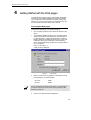
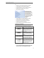
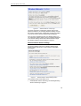
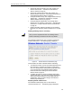
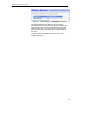
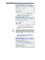
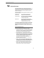
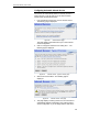
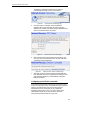
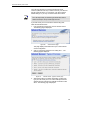
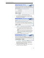
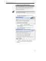
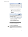
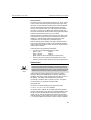
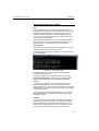
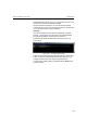
ADSL/VoIP Gateway User’s Guide Figure 80: Internet Access: VPI and VCI Setup page 4. At this page, click on the VCI and VPI setting determined by your ISP: • Fixed (default) - click on this if your ISP tells you to use default VPI and VCI setting. This is the most common setup. Manual – click on this if your ISP has provided you with specific VPI and VCI settings. Click Next>. At the next page, type the provided VPI and VCI settings in the relevant boxes. 5. Click Next>. The following page is displayed: • Figure 81: Internet Access: Confirm page This page confirms your DHCP settings. If you selected the Manual option at step 4, the VPI and VCI values that you entered are also displayed on this page. 6. If you are happy with your settings, click Confirm Changes. The Internet Access page is displayed and your configuration is complete. Configuring your Internet Access manually If your ISP tells you to configure your Internet access manually, they must provide you with the following information: Note • The WAN IP address and subnet mask for your device • The Internet Gateway address • The primary and secondary DNS addresses You should only change the Internet Access details if your ISP asks you to, or if you are familiar with network configuration. In most cases, you will not need to make any changes to this configuration. 1. From the left-hand Setup menu, click on Internet Access. The following page is displayed: 71 ADSL/VoIP Gateway User’s Guide Figure 82: Internet Access page This page displays information about your current Internet access configuration. 2. Click on Change the Internet Access setting here… The following page is displayed: Figure 83: Internet Access: Types of Access page 3. Select Manual then click Next>. The following page is displayed: Figure 84: Internet Access: Manual Setup page 4. Click in each box and type the relevant address information provided by your ISP. Click Next>. The following page is displayed: 72 ADSL/VoIP Gateway User’s Guide Figure 85: Internet Access: VPI and VCI Setup page 5. At this page, click on the VCI and VPI setting determined by your ISP: • Fixed (default) - click on this if your ISP tells you to use default VPI and VCI settings. This is the most common setup. Manual – click on this if your ISP has provided you with specific VPI and VCI settings. Click Next>. At the next page, type the provided VPI and VCI settings in the relevant boxes. 6. Click Next>. The following page is displayed: • Figure 86: Internet Access: Confirm page This page confirms the address settings that you have manually configured (the values displayed above are for example purposes only). If you selected the Manual option at step 5, the VPI and VCI values that you entered are also displayed on this page. 7. If you are happy with your settings, click Confirm Changes. The Internet Access page is displayed and your configuration is complete. 73 ADSL/VoIP Gateway User’s Guide 13 Password You can restrict access to your device’s web pages using password protection. With password protection enabled, users must enter a username and password before gaining access to the web pages. By default, password protection is enabled on your device, and the username and password set are as follows: Username: admin Password: admin For more information, see Accessing the Web pages on page 19. Setting your username and password Note Non-authorized users may try to access your system by guessing your username and password. We recommend that you change the default username and password to your own unique settings. To set your own username and password: 1. From the left-hand Setup menu, click on Password. The following page is displayed: Figure 87: Password page This page displays the current status of password protection. 2. Click on Change Password settings here… The following page is displayed: Figure 88: Password: Enable/Disable page 74 ADSL/VoIP Gateway User’s Guide 3. This page allows you to enable or disable password protection. Protection is already enabled by default. Click Next>. The following page is displayed: Figure 89: Password: Setup page 4. This page displays the current username and password settings. Type your own unique username and password in the relevant boxes. They can be any combination of letters or numbers with a maximum of 20 characters. The default setting uses admin for both the username and password. We recommend that you do not set the same character combination for both username and password. 5. Click Next>. The following page is displayed: Figure 90: Password: Confirm page 6. This page confirms that password protection is enabled and displays the username that will be required in order to access the web pages. If you are happy with these settings, click Confirm Changes. The Enter Network Password login box is displayed. You need to login to the web pages using your new username and password. For details of how to do this, see Accessing the Web pages on page 19. Disabling password protection If you do not want to use password protection, follow the instructions in Setting your username and password on page 74 and at step 3, select Disable and then click Next>. 75 ADSL/VoIP Gateway User’s Guide 14 Reset to Defaults This page allows you to reset your device to its default factory settings. The configuration settings of your device are stored in a configuration file. When you set up your device and access the web pages for the very first time, the configuration file contains a default factory configuration. This configuration has been set by Multitek for you, and contains the basic settings that you can use without having to make extensive changes to the configuration. If you do make changes to the default configuration but then wish to revert back to the original factory configuration, you can do so by resetting the device to factory defaults. Resetting to Defaults Note If you reset your device to factory defaults, all previous configuration changes that you have made are overwritten by the factory default configuration. 1. From the left-hand Setup menu, click on Reset to Defaults. The following page is displayed: Figure 91: Reset to Defaults page 2. This page reminds you that resetting to factory defaults cannot be undone – any changes that you have made to the basic settings will be replaced. If you are happy with this, click in the Confirm box to tick it, then click Reset to Defaults. The following page is displayed: Figure 92: Resetting to Defaults… page This page confirms that the device is currently resetting to factory defaults. Once the reset is complete, the Current Status page is displayed. See Current Status on page 24. 76 ADSL/VoIP Gateway User’s Guide Note Resetting to defaults also resets the username and password to their default settings. If you previously changed the username and password by following the instructions in Password on page 74, the Enter Current Password login box will be displayed. Once you have entered the default settings (admin, admin) and clicked OK, the Current Status page is displayed. 77 ADSL/VoIP Gateway User’s Guide 15 VoIP VoIP enables telephone calls to be made over an IP network. This enables DSL Service providers to sell telephone services over DSL to customers without the expense of providing any extra physical connections to the consumer, or network infrastructure in addition to their existing IP network.The DSL Service provider can build VoIP functionality into their DSL Modem product to create a Voice-IAD (Integrated Access Device) system. The Voice-IAD system would typically offer connections for the DSL line, Ethernet and/or Wireless LAN, together with one or more analog telephone sockets to enable the user to make telephone calls over the IP network or over the PSTN. The decision on whether to route the call over the telephone network or the PSTN would depend on the number dialled and the status of the Internet connection. This feature is known as Call Routing . The following diagram illustrates the interfaces that would be provided on a typical Comm-Box system: Figure 93: Comm-Box System Interfaces The DSL/FXO interface refers to a single connector with a POTS filter supporting connection of DSL and PSTN to the system. In practice, the filter may be external and an additional FXO socket provided. FXS refers to the low-cost phone ports (digitally connected on the board to VoIP or PSTN). 78 ADSL/VoIP Gateway User’s Guide The product provides Internet access using DSL for the LAN and Wireless LAN computers. The phones connected to the Voice-IAD system are standard analog phones that are identical to the other telephones connected to the Home telephone wiring system. The phones can use DTMF or Pulse dialling to make either PSTN or VoIP calls. The Voice-IAD system will route or receive calls over PSTN or VoIP depending on the dialed telephone number or the way in which an incoming call is received. In cases where the VoIP call agent cannot be reached, the DSL line is down or there is no power - calls will always be routed to the PSTN via a Failsafe relay (hence the phones will be electrically connected to the PSTN). QoS (Quality of Service) is also used to ensure voice calls are placed at a higher priority than data traffic routed between the LAN/WLAN and DSL interface. Voice Terminology Before beginning an overview ,several Voice and telephony terms must be understood. FXS Telephones, fax machines, and modems are examples of telephony devices. These devices typically connect (via telephone lines) to RJ11-jack Foreign Exchange Station (FXS) interfaces on telephony hardware. The FXS interface provides battery, signaling and an audio connection for the devices. FXO An FXO interface is the Foreign Exchange Office interface which connects to a PSTN Exchange. Codec Audio data from the FXS port or FXO port is sampled via an analog-to-digital converter, and audio data to the FXS port is generated via a digital-to-analog converter. These functions are integrated into a single circuit, the codec (short for coderdecoder, since typically, codecs encode/decode audio samples using 8-bit or 16-bit PCM encoding). Codec integrated circuits may handle bidirectional audio data on single or multiple FXS ports, or FXO ports. The codec produces a constant stream of audio data in a Time Division Multiplexed (TDM) fashion, which places the audio data from each port into time slots. The TDM transmission is synchronized into ‘frames’ of audio data by aligning with the codec's ‘frame sync’ signal. An FXS port's time slot is referred to as an ‘audio channel.’ In a typical VoIP system the Codec is a separate chip but it is more accurate to view the codec as an integral component of the overall integrated circuit functionality. Voice features The main Voice features supported in the Voice software release are listed below: 79 ADSL/VoIP Gateway User’s Guide • VoIP with PSTN switching for up to two FXS ports for handling VoIP calls and PSTN calls based on the number dialled and the IP/DSL connection status. • Soft Relay support to handle connections between the FXS and FXO ports. • Hard ‘Failsafe’ Relay to switch FXS ports directly to the FXO port in the event of a power failure or loss of Internet connectivity. • Health Monitor to monitor the state of the IP/DSL connection and indicate this status to onboard LEDs and control the Failsafe relay. Telephony data processing features The main telephony data processing functions supported in the Voice software release are listed below: • Voice codec support: • G.711 (A-Law and µ−Law), • G.726 (32kb) and • G.729ab The codecs can be dynamically changed during a call. • Echo cancellation (G.168, 32ms echo-tail (configurable)) • Silence suppression (Voice Activity Detection (VAD)) and Comfort Noise Generation (CNG). • Dynamic Packet Loss Compensation. • Configurable Adaptive Jitter buffer. • Telephony timing synchronization with Time Division Multiplexed (TDM) audio data. • Fax and Modem tone detection. • DTMF generation and detection. • Highly configurable and versatile Tone generator for call progress tones and special information tones. VoIP Configuration Your device can automatically search for a link to your VoIP service provider. If your VoIP service provider tells you to use this connection method, follow the instructions below. 1. From the left-hand Setup menu, click on VOIP. The following page is displayed: 80 ADSL/VoIP Gateway User’s Guide Figure 94: VOIP Page System Settings 2. Voip Functionality: Select SIP as VoIP protocol. 3. Select Region to define your country region. It is shown in Figure 95 4. CidType (Caller Id Type) is chosen FSK or DMTF. This option is defined by your VoIP telephony service provider. 5. DTMF Mode is chosen Inband or RFC2833. 6. Click apply to execute new values. 81 ADSL/VoIP Gateway User’s Guide Figure 95: Region page SIP Settings SIP setting page is shown in Figure 96. 7. Registrar, Proxy, Outbound Server and User Domain are filled with their web address name ( as sip.XXXX.org ) which are obtained from your telephony service provider. Their port numbers and their transport protocols (TCP or UDP) are also defined according to the telephony operator information. 8. Silence Suppression ( voice activation ) and echo cancellations can be enable or disable, separately. 9. Click to Apply to execute the editing values. 82 ADSL/VoIP Gateway User’s Guide Figure 96: SIP Setting Page Dialling Plan Figure 97: Dialling Plan 83 ADSL/VoIP Gateway User’s Guide SIP Calling Digitmap is a regular expression string which defines a pattern of digits which will be recognised by the system as a valid phone number. The digit map can be used to specify not only the number of digits required to make a valid phone number but also the range of digits and special characters which can be entered and timeout values after the digits have been dialled. For example, here is an example of a digit map: ([1-8]xxx|#xxxxxx|*xx) This digit map defines a valid phone number as being one of the following: • Any digit between 1and 8 followed by any three numbers. • A ‘#’ symbol followed by any six numbers • A ‘*’ symbol followed by any two numbers The Digitmap can also be extended to include special call codes such as speed dialling or last number redial. An ‘S’ at the end of a section of a digit map defines a special call code. For example, in the digit map: (xxxx|##S) This digitmap defines a special call code such that if ‘##’ is dialled the last number dialled from the phone will be redialled. Other options are shown in Figure 98. Figure 98: Special Dialling Codes Another example is helpful to recognize digitmap 84 ADSL/VoIP Gateway User’s Guide (x.T|##S|*[268]xS|*74x.#S|x#S|*90x.#S) The above digitmap sets the following characteristics for the SIP phones: • x.T - any number of digits followed by a timeout to dial the digits. This is not a special call code. • ##S - Last number redial. • *[268]xS - is a compound entry which matches the following codes: • *20 - Set DND (Do-Not-Disturb) ON • *80 - Set DND (Do-Not-Disturb) OFF • *69 - Return the last missed call All other numbers which are also matched by this entry will return an error if entered. For example, entering *82 will generate an error. • *74x.#S - Speed dial 8 setting. • x#S - Speed dial call. • *90x.#S - SIP blind transfer. PSTN Calling Rules PSTN rules can determined in the same page as shown in Figure 97. This facility enables you to configure ‘VoIP with PSTN switching’ on your system. Using this values the user can define a range of dial plans which specify the numbers which are connected to the PSTN. If the number dialled matches a number defined in the dial plan, then the number is routed to the PSTN. Create a new PSTN rules opens new windows as shown in Figure 99. Figure 99: PSTN Calling Rule Pages 85 ADSL/VoIP Gateway User’s Guide The following table gives the range of values for each option which can be specified with this command and a default value (if applicable): Figure 100: PSTN rules details Quality of Service (QoS) Settings QoS (Quality of Service) is used to ensure voice calls are at a higher priority than traffic routed between the LAN/WLAN and DSL interface. Figure 101: . Quality of Service The voice software generates packets with the transmit priority of the data buffer set to 7 (the default, best effort, priority is 0). 86 ADSL/VoIP Gateway User’s Guide Endpoints Two POTS telephones can be connected for VoIP calls. Their numbers, which are given by your Telecom Operator, have to be defined as endpoints. Edit buttons as shown in Figure 102 are used. If it is clicked, the edit page will be appeared as in Figure 103. Figure 102: Figure 103: Endpoints Edit Endpoints Detail Endpoint Name, Display Name and Password Box have to be filled correctly, then Apply button should be clicked. 87 ADSL/VoIP Gateway User’s Guide A Configuring your Computers Configuring your Computers This appendix provides instructions for configuring the Internet settings on your computers to work with the Hata! Stil tanımlanmamış.. Configuring Ethernet PCs Before you begin By default, the Hata! Stil tanımlanmamış. automatically assigns the required Internet settings to your PCs. You need to configure the PCs to accept this information when it is assigned. 10. In some cases, you may want to assign Internet information manually to some or all of your computers rather than allow the Hata! Stil tanımlanmamış. to do so. See Note Assigning static Internet information to your PCs on page 92 for instructions. • • If you have connected your LAN PCs via Ethernet to the Hata! Stil tanımlanmamış., follow the instructions that correspond to the operating system installed on your PC: • Windows® XP PCs on page 89 • Windows 2000 PCs on page 90 • Windows Me PCs on page 91 • Windows 95, 98 PCs on page 91 • Windows NT 4.0 workstations on page 91 If you want to allow Wireless PCs to access your device, follow the instructions in Configuring Wireless PCs on page 96. Windows® XP PCs 1. In the Windows task bar, click the Start button, and then click Control Panel. 2. Double-click the Network Connections icon. 3. In the LAN or High-Speed Internet window, right-click on the icon corresponding to your network interface card (NIC) and select Properties. (Often, this icon is labeled Local Area Connection). The Local Area Connection dialog box is displayed with a list of currently installed network items. 88 Biçimlendirilmiş: Madde Đşaretleri ve Numaralandırma ADSL/VoIP Gateway User’s Guide Configuring your Computers 4. Ensure that the check box to the left of the item labeled Internet Protocol TCP/IP is checked and click Properties. 5. In the Internet Protocol (TCP/IP) Properties dialog box, click the radio button labeled Obtain an IP address automatically. Also click the radio button labeled Obtain DNS server address automatically. 6. Click OK twice to confirm your changes, and then close the Control Panel. Windows 2000 PCs First, check for the IP protocol and, if necessary, install it: 1. In the Windows task bar, click the Start button, point to Settings, and then click Control Panel. 2. Double-click the Network and Dial-up Connections icon. 3. In the Network and Dial-up Connections window, right-click the Local Area Connection icon, and then select Properties. The Local Area Connection Properties dialog box is displayed with a list of currently installed network components. If the list includes Internet Protocol (TCP/IP), then the protocol has already been enabled. Skip to step 10. 4. If Internet Protocol (TCP/IP) does not display as an installed component, click Install… 5. In the Select Network Component Type dialog box, select Protocol, and then click Add… 6. Select Internet Protocol (TCP/IP) in the Network Protocols list, and then click OK. You may be prompted to install files from your Windows 2000 installation CD or other media. Follow the instructions to install the files. 7. If prompted, click OK to restart your computer with the new settings. Next, configure the PCs to accept IP information assigned by the Hata! Stil tanımlanmamış.: 8. In the Control Panel, double-click the Network and Dial-up Connections icon. 9. In the Network and Dial-up Connections window, right-click the Local Area Connection icon, and then select Properties. 10. In the Local Area Connection Properties dialog box, select Internet Protocol (TCP/IP), and then click Properties. 11. In the Internet Protocol (TCP/IP) Properties dialog box, click the radio button labeled Obtain an IP address automatically. Also click the radio button labeled Obtain DNS server address automatically. 12. Click OK twice to confirm and save your changes, and then close the Control Panel. 89 ADSL/VoIP Gateway User’s Guide Configuring your Computers Windows Me PCs 1. In the Windows task bar, click the Start button, point to Settings, and then click Control Panel. 2. Double-click the Network and Dial-up Connections icon. 3. In the Network and Dial-up Connections window, right-click the Network icon, and then select Properties. The Network Properties dialog box displays with a list of currently installed network components. If the list includes Internet Protocol (TCP/IP), then the protocol has already been enabled. Skip to step 11. 4. If Internet Protocol (TCP/IP) does not display as an installed component, click Add… 5. In the Select Network Component Type dialog box, select Protocol, and then click Add… 6. Select Microsoft in the Manufacturers box. 7. Select Internet Protocol (TCP/IP) in the Network Protocols list, and then click OK. You may be prompted to install files from your Windows Me installation CD or other media. Follow the instructions to install the files. 8. If prompted, click OK to restart your computer with the new settings. Next, configure the PCs to accept IP information assigned by the Hata! Stil tanımlanmamış.: 9. In the Control Panel, double-click the Network and Dial-up Connections icon. 10. In Network and Dial-up Connections window, right-click the Network icon, and then select Properties. 11. In the Network Properties dialog box, select TCP/IP, and then click Properties. 12. In the TCP/IP Settings dialog box, click the radio button labeled Server assigned IP address. Also click the radio button labeled Server assigned name server address. 13. Click OK twice to confirm and save your changes, and then close the Control Panel. Windows 95, 98 PCs First, check for the IP protocol and, if necessary, install it: 1. In the Windows task bar, click the Start button, point to Settings, and then click Control Panel. 2. Double-click the Network icon. The Network dialog box displays with a list of currently installed network components. If the list includes TCP/IP, and then the protocol has already been enabled. Skip to step 9. 90 ADSL/VoIP Gateway User’s Guide Configuring your Computers 3. If TCP/IP does not display as an installed component, click Add… The Select Network Component Type dialog box displays. 4. Select Protocol, and then click Add… The Select Network Protocol dialog box displays. 5. Click on Microsoft in the Manufacturers list box, and then click TCP/IP in the Network Protocols list box. 6. Click OK to return to the Network dialog box, and then click OK again. You may be prompted to install files from your Windows 95/98 installation CD. Follow the instructions to install the files. 7. Click OK to restart the PC and complete the TCP/IP installation. Next, configure the PCs to accept IP information assigned by the Hata! Stil tanımlanmamış.: 8. Open the Control Panel window, and then click the Network icon. 9. Select the network component labeled TCP/IP, and then click Properties. If you have multiple TCP/IP listings, select the listing associated with your network card or adapter. 10. In the TCP/IP Properties dialog box, click the IP Address tab. 11. Click the radio button labeled Obtain an IP address automatically. 12. Click the DNS Configuration tab, and then click the radio button labeled Obtain an IP address automatically. 13. Click OK twice to confirm and save your changes. You will be prompted to restart Windows. 14. Click Yes. Windows NT 4.0 workstations First, check for the IP protocol and, if necessary, install it: 1. In the Windows NT task bar, click the Start button, point to Settings, and then click Control Panel. 2. In the Control Panel window, double click the Network icon. 3. In the Network dialog box, click the Protocols tab. The Protocols tab displays a list of currently installed network protocols. If the list includes TCP/IP, then the protocol has already been enabled. Skip to step 9. 4. If TCP/IP does not display as an installed component, click Add… 5. In the Select Network Protocol dialog box, select TCP/IP, and then click OK. 91 ADSL/VoIP Gateway User’s Guide Configuring your Computers You may be prompted to install files from your Windows NT installation CD or other media. Follow the instructions to install the files. After all files are installed, a window displays to inform you that a TCP/IP service called DHCP can be set up to dynamically assign IP information. 6. Click Yes to continue, and then click OK if prompted to restart your computer. Next, configure the PCs to accept IP information assigned by the Hata! Stil tanımlanmamış.: 7. Open the Control Panel window, and then double-click the Network icon. 8. In the Network dialog box, click the Protocols tab. 9. In the Protocols tab, select TCP/IP, and then click Properties. 10. In the Microsoft TCP/IP Properties dialog box, click the radio button labeled Obtain an IP address from a DHCP server. 11. Click OK twice to confirm and save your changes, and then close the Control Panel. Assigning static Internet information to your PCs If you are a typical user, you will not need to assign static Internet information to your LAN PCs because your ISP automatically assigns this information for you. In some cases however, you may want to assign Internet information to some or all of your PCs directly (often called “statically”), rather than allowing the Hata! Stil tanımlanmamış. to assign it. This option may be desirable (but not required) if: • You have obtained one or more public IP addresses that you want to always associate with specific computers (for example, if you are using a computer as a public web server). • You maintain different subnets on your LAN (subnets are described in Appendix B). Before you begin, you must have the following information available: • The IP address and subnet mask of each PC • The IP address of the default gateway for your LAN. In most cases, this is the address assigned to the LAN port on the Hata! Stil tanımlanmamış.. By default, the LAN port is assigned the IP address 192.168.1.1. (You can change this number or another number can be assigned by your ISP. See Addressing on page 40 for more information.) • The IP address of your ISP’s Domain Name System (DNS) server. On each PC to which you want to assign static information, follow the instructions on pages 93 through 96 relating only to checking for and/or installing the IP protocol. Once it is installed, continue 92 ADSL/VoIP Gateway User’s Guide Configuring your Computers to follow the instructions for displaying each of the Internet Protocol (TCP/IP) properties. Instead of enabling dynamic assignment of the IP addresses for the computer, DNS server and default gateway, click the radio buttons that enable you to enter the information manually. Note Your PCs must have IP addresses that place them in the same subnet as the Hata! Stil tanımlanmamış.’s LAN port. If you manually assign IP information to all your LAN PCs, you can follow the instructions in Addressing on page 40 to change the LAN port IP address accordingly. 93 ADSL/VoIP Gateway User’s Guide Configuring your Computers 94 ADSL/VoIP Gateway User’s Guide Configuring your Computers Configuring Wireless PCs You need to configure the operating system installed on your Wireless PCs using the same procedure described for Configuring Ethernet PCs on page 89. Positioning the wireless PCs The wireless network cards used determine the maximum distance between your wireless PCs and your device. Guidelines on positioning the hardware components of your wireless network should be provided by your network card provider. Wireless PC cards and drivers Each PC on your wireless LAN must be fitted with a wireless access card. You must also install the corresponding driver files for your particular wireless card on your PC. You should receive driver files and instructions on how to install them together with your wireless card. Configuring PC access to your Wireless device Before you start configuring your Wireless PC, you must ensure that you have: • A Wireless access card for each of the PCs • Corresponding wireless access card driver software files The configuration steps below will vary depending on both the operating system and wireless card installed on the PC. These steps provide a basic outline, however you should refer to the documentation provided with your wireless access card for specific instructions. To configure your Wireless PCs: 1. 2. 3. Install the wireless access card. Install the wireless driver software files. Configure the following wireless parameters on each of the wireless PCs: a. Set the adapter to use infrastructure mode. This configures the PCs to access each other and the Internet via the device. b. Configure the SSID and channel to match the SSID and channel previously configured on the device (see Set the Wireless Network Name on page 44 and Select a Channel on page 45). Your wireless network can now communicate with the Internet via the device. 95 ADSL/VoIP Gateway User’s Guide B IP Addresses, Network Masks, and Subnets IP Addresses, Network Masks, and Subnets IP Addresses This section refers only to IP addresses for IPv4 (version 4 of the Internet Protocol). IPv6 addresses are not covered. This section assumes basic knowledge of binary numbers, bits, and bytes. Note IP addresses, the Internet's version of telephone numbers, are used to identify individual nodes (computers or devices) on the Internet. Every IP address contains four numbers, each from 0 to 255 and separated by dots (periods), e.g. 20.56.0.211. These numbers are called, from left to right, field1, field2, field3, and field4. This style of writing IP addresses as decimal numbers separated by dots is called dotted decimal notation. The IP address 20.56.0.211 is read "twenty dot fifty-six dot zero dot two-eleven." Structure of an IP address IP addresses have a hierarchical design similar to that of telephone numbers. For example, a 7-digit telephone number starts with a 3digit prefix that identifies a group of thousands of telephone lines, and ends with four digits that identify one specific line in that group. Similarly, IP addresses contain two kinds of information: • Network ID Identifies a particular network within the Internet or intranet • Host ID Identifies a particular computer or device on the network The first part of every IP address contains the network ID, and the rest of the address contains the host ID. The length of the network ID depends on the network's class (see following section). The table below shows the structure of an IP address. Field1 Class A Class B Class C Field2 Network ID Field3 Field4 Host ID Network ID Network ID Host ID Host ID Here are some examples of valid IP addresses: Class A: 10.30.6.125 (network = 10, host = 30.6.125) Class B: 129.88.16.49 (network = 129.88, host = 16.49) Class C: 192.60.201.11 (network = 192.60.201, host = 11) 97 ADSL/VoIP Gateway User’s Guide IP Addresses, Network Masks, and Subnets Network classes The three commonly used network classes are A, B, and C. (There is also a class D but it has a special use beyond the scope of this discussion.) These classes have different uses and characteristics. Class A networks are the Internet's largest networks, each with room for over 16 million hosts. Up to 126 of these huge networks can exist, for a total of over 2 billion hosts. Because of their huge size, these networks are used for WANs and by organizations at the infrastructure level of the Internet, such as your ISP. Class B networks are smaller but still quite large, each able to hold over 65,000 hosts. There can be up to 16,384 class B networks in existence. A class B network might be appropriate for a large organization such as a business or government agency. Class C networks are the smallest, only able to hold 254 hosts at most, but the total possible number of class C networks exceeds 2 million (2,097,152 to be exact). LANs connected to the Internet are usually class C networks. Some important notes regarding IP addresses: • The class can be determined easily from field1: field1 = 1-126: Class A field1 = 128-191: Class B field1 = 192-223: Class C (field1 values not shown are reserved for special uses) • A host ID can have any value except all fields set to 0 or all fields set to 255, as those values are reserved for special uses. Subnet masks Definition mask A mask looks like a regular IP address, but contains a pattern of bits that tells what parts of an IP address are the network ID and what parts are the host ID: bits set to 1 mean "this bit is part of the network ID" and bits set to 0 mean "this bit is part of the host ID." Subnet masks are used to define subnets (what you get after dividing a network into smaller pieces). A subnet's network ID is created by "borrowing" one or more bits from the host ID portion of the address. The subnet mask identifies these host ID bits. For example, consider a class C network 192.168.1. To split this into two subnets, you would use the subnet mask: 255.255.255.128 It's easier to see what's happening if we write this in binary: 11111111. 11111111. 11111111.10000000 As with any class C address, all of the bits in field1 through field3 are part of the network ID, but note how the mask specifies that the first bit in field4 is also included. Since this extra bit has only two values (0 and 1), this means there are two subnets. Each subnet uses the remaining 7 bits in field4 for its host IDs, which range from 1 to 126 hosts (instead of the usual 0 to 255 for a class C address). 98 ADSL/VoIP Gateway User’s Guide IP Addresses, Network Masks, and Subnets Similarly, to split a class C network into four subnets, the mask is: 255.255.255.192 or 11111111. 11111111. 11111111.11000000 The two extra bits in field4 can have four values (00, 01, 10, 11), so there are four subnets. Each subnet uses the remaining six bits in field4 for its host IDs, ranging from 1 to 62. Sometimes a subnet mask does not specify any additional network ID bits, and thus no subnets. Such a mask is called a default subnet mask. These masks are: Note Class A: Class B: Class C: 255.0.0.0 255.255.0.0 255.255.255.0 These are called default because they are used when a network is initially configured, at which time it has no subnets. 99 ADSL/VoIP Gateway User’s Guide C Troubleshooting Troubleshooting This appendix suggests solutions for problems you may encounter in installing or using the Hata! Stil tanımlanmamış., and provides instructions for using several IP utilities to diagnose problems. Contact Customer Support if these suggestions do not resolve the problem. Troubleshooting Suggestions Problem Troubleshooting Suggestion LEDs Power LED does not illuminate after product is turned on. Internet LED does not illuminate after phone cable is attached. LINK LAN LED does not illuminate after Ethernet cable is attached. Verify that you are using the power cable provided with the device and that it is securely connected to the Hata! Stil tanımlanmamış. and a wall socket/power strip. Verify that a standard telephone cable (called an RJ-11 cable) like the one provided is securely connected to the DSL port and your wall phone port. Allow about 30 seconds for the device to negotiate a connection with your ISP. Verify that the Ethernet cable is securely connected to your LAN hub or PC and to the Hata! Stil tanımlanmamış.. Make sure the PC and/or hub is turned on. Verify that your cable is sufficient for your network requirements. A 100 Mbit/sec network (10BaseTx) should use cables labeled CAT 5. A 10Mbit/sec network may tolerate lower quality cables. Internet Access My PC cannot access the Internet Run a health check on your device. See Health Check on page 31. Use the ping utility (discussed in the following section) to check whether your PC can communicate with the device’s LAN IP address (by default 192.168.1.1). If it cannot, check the Ethernet cabling. If you statically assigned a private IP address to the computer, (not a registered public address), verify the following: • Check that the gateway IP address on the computer is your public IP address (see Current Status on page 10 for instructions on viewing the IP information.) If it is not, correct the address or configure the PC to receive IP information automatically. • Verify with your ISP that the DNS server specified for the PC is valid. Correct the address or configure the PC to receive this information automatically. 100 ADSL/VoIP Gateway User’s Guide Troubleshooting Problem Troubleshooting Suggestion My LAN PCs cannot display web pages on the Internet. Verify that the DNS server IP address specified on the PCs is correct for your ISP, as discussed in the item above. If you specified that the DNS server be assigned dynamically from a server, then verify with your ISP that the address configured on the Hata! Stil tanımlanmamış. is correct, then You can use the ping utility, discussed on page 102, to test connectivity with your ISP’s DNS server. Web pages I forgot/lost my user ID or password. I cannot access the web pages from my browser. My changes to the web pages are not being retained. If you have not changed the password from the default, try using “admin” as both the user ID and password. Otherwise, you can reset the device to the default configuration by pressing the Reset Default button on the front panel of the device (see Front Panel on page 14). Then, type the default User ID and password shown above. WARNING: Resetting the device removes any custom settings and returns all settings to their default values. Use the ping utility, discussed in the following section, to check whether your PC can communicate with the device’s LAN IP address (by default 192.168.1.1). If it cannot, check the Ethernet cabling. Verify that you are using Internet Explorer or Netscape Navigator v4.0 or later. Verify that the PC’s IP address is defined as being on the same subnet as the IP address assigned to the LAN port on the Hata! Stil tanımlanmamış.. Be sure to use the Confirm Changes function after any changes. 101 ADSL/VoIP Gateway User’s Guide Troubleshooting Diagnosing Problem using IP Utilities ping Ping is a command you can use to check whether your PC can recognize other computers on your network and the Internet. A ping command sends a message to the computer you specify. If the computer receives the message, it sends messages in reply. To use it, you must know the IP address of the computer with which you are trying to communicate. On Windows-based computers, you can execute a ping command from the Start menu. Click the Start button, and then click Run. In the Open text box, type a statement such as the following: ping 192.168.1.1 Click OK. You can substitute any private IP address on your LAN or a public IP address for an Internet site, if known. If the target computer receives the message, a Command Prompt window is displayed: Figure 104: Using the ping Utility If the target computer cannot be located, you will receive the message Request timed out. Using the ping command, you can test whether the path to the Hata! Stil tanımlanmamış. is working (using the preconfigured default LAN IP address 192.168.1.1) or another address you assigned. You can also test whether access to the Internet is working by typing an external address, such as that for www.yahoo.com (216.115.108.243). If you do not know the IP address of a particular Internet location, you can use the nslookup command, as explained in the following section. From most other IP-enabled operating systems, you can execute the same command at a command prompt or through a system administration utility. nslookup You can use the nslookup command to determine the IP address associated with an Internet site name. You specify the common name, and the nslookup command looks up the name in on your DNS server (usually located with your ISP). If that name is not an entry in your ISP’s DNS table, the request is then referred to 102 ADSL/VoIP Gateway User’s Guide Troubleshooting another higher-level server, and so on, until the entry is found. The server then returns the associated IP address. On Windows-based computers, you can execute the nslookup command from the Start menu. Click the Start button, and then click Run. In the Open text box, type the following: Nslookup Click OK. A Command Prompt window displays with a bracket prompt (>). At the prompt, type the name of the Internet address that you are interested in, such as www.microsoft.com. The window will display the associate IP address, if known, as shown below: Figure 105: Using the nslookup Utility There may be several addresses associated with an Internet name. This is common for web sites that receive heavy traffic; they use multiple, redundant servers to carry the same information. To exit from the nslookup utility, type exit and press [Enter] at the command prompt. 103 ADSL/VoIP Gateway User’s Guide D Advanced DSL port attributes Advanced DSL port attributes The following table displays detailed information about the advanced DSL port attributes. These attributes are displayed on the Port A1 Advanced Configuration page (part 1) and Port A1 Advanced Configuration page (part 2). Note Attribute DSP Firmware Version You should only need to refer to these attributes if your ISP has asked you to check something or if you are experienced in DSL port configuration. Value DSP code version number Default N/A DSP Version DSL driver version number Connected Current connected state: True – modem is connected to a remote modem False – modem is not connected to a remote modem N/A Operational Mode Current operating (connected) mode (modulation) State Current state of the device: Idle – not connected or attempting to connect HandShake – connecting/hunting for remote modem Training – connecting/found a remote modem Showtime – connected to remote modem N/A Watchdog Watchdog timer which confirms that the DSP is executing a program correctly N/A Operation Progress Detailed startup information to be used for debugging N/A Last Failed This value is reset to 0 each time a startup is attempted. If there is a failure, it indicates the reason for the failure. N/A Tx Bit Rate Transmit rate (bits per second) of the device N/A Rx Bit Rate Receive rate (bits per second) of the device N/A Tx Cell Rate Transmit rate (cells per second) of the device N/A Rx Cell Rate Receive rate (cells per second) of the device N/A False Inactive Phy TXCell Count Transmit ATM cell counter N/A Phy RXCell Count Receive ATM cell counter N/A Phy Cell Drop Count UTOPIA cell drop counter N/A Overall Failure Indicates the cause of failure N/A Local ITUCountry Code Country code used by the device (modulation specific) N/A Local SEF Number of severely errored frame defects received by the device N/A Local End LOS Number of loss of signal defects received by the device N/A Local SNRMargin The local Signal to Noise Ration margin N/A Local Line Attn The local attenuation values N/A Local Tx Power Current transmit power attenuation of the device N/A 104 ADSL/VoIP Gateway User’s Guide Attribute Advanced DSL port attributes Value Default Local Fast Channel Rx Rate Receive rate (bits per second) of the device on the fast path N/A Local Fast Channel Tx Rate Transmit rate (bits per second) of the device on the fast path N/A Local Fast Channel FEC Instances of Forward Error Correction required by the device on the fast channel N/A Local Fast Channel CRC Number of CRC errors received by the device on the fast channel N/A Local Fast Channel HEC Number of ATM Cell Header errors corrected by the device on the fast channel N/A Local Fast Channel NCD Number of no cell delineation received by the device on the fast channel N/A Local Fast Channel OCD Number of out of cell delineation received by the device on the fast channel N/A Local Interleaved Channel Rx Rate Receive rate (bits per second) of the device on the interleaved path N/A Local Interleaved Channel Tx Rate Transmit rate (bits per second) of the device on the interleaved path N/A Local Interleaved Channel FEC Instances of Forward Error Correction required by the device on the interleaved channel N/A Local Interleaved Channel CRC Number of CRC errors received by the device on the interleaved channel N/A Local Interleaved Channel HEC Number of ATM Cell Header errors corrected by the device on the interleaved channel N/A Local Interleaved Channel NCD Number of no cell delineation received by the device on the interleaved channel N/A Local Interleaved Channel OCD Number of out of cell delineation received by the device on the interleaved channel N/A Remote SEF Number of severely errored frame defects received by the device N/A Remote LOS Number of loss of signal defects received by the device N/A Remote Line Attn The remote attenuation values N/A Remote SNRMargin The remote Signal to Noise Ration margin N/A Remote Fast Channel FEC Instances of Forward Error Correction required by the device on the fast channel N/A Remote Fast Channel CRC Number of CRC errors received by the device on the fast channel N/A Remote Fast Channel HEC Number of ATM Cell Header errors corrected by the device on the fast channel N/A Remote Fast Channel NCD Number of no cell delineation received by the device on the fast channel N/A Remote Interleaved Channel FEC Instances of Forward Error Correction required by the device on the interleaved channel N/A Remote Interleaved Channel CRC Number of CRC errors received by the device on the interleaved channel N/A Remote Interleaved Channel HEC Number of ATM Cell Header errors corrected by the device on the interleaved channel N/A Remote Interleaved Channel NCD Number of no cell delineation received by the device on the interleaved channel N/A 105 ADSL/VoIP Gateway User’s Guide Attribute Advanced DSL port attributes Value Default Activate Line Abort – deactivates the DSL link None – signifies that this parameter has been read Start – activates the DSL link None Host Control Disable – terminates any host/API interaction with the DSP (for testing purposes) Enable – enables host/API interaction with the DSP Auto Start “True” - A Connection will be established at power up. “False” - The modem will remain in Idle mode at power up. True Failsafe True – a failsafe timer is activated when a startup request is made. Once a connection has been established, the failsafe timer is disabled False – a failsafe timer is not activated when a startup request is made True PSMode Possible Values: “Inner” : Inner Pair Selected “Outer” : Outer Pair Selected This attribute is only present if Pair switching is enabled. Inner Whip Possible Values if compiled for Whip Serial: Serial or Inactive Possible Values if compiled for Whip TCP: TCP or Inactive Possible Values if compiled for Whip Serial/TCP: Serial, TCP or Inactive Inactive Whip Active Indicated state of whip. Possible values are Inactive, SerialActive and TCPActive Inactive Action An action given when ActivateLine is set to Start. Possible values are Startup, SpectrumReverb, SpectrumMedely or SpectrumPilot Startup Standard Indicates the preferred standard compliance. Multimode indicates that the device automatically detects the other end as one of the supported standards. Multimode Utopia Interface Level1 – Utopia Level 1 internal framing is used with the DSP Level2 – Utopia Level 2 internal framing is used with the DSP Level1 EC FDM Mode EC – enables Echo Cancellation. This setting is necessary if your device is connected to a high speed CO. FDM – enables Frequency Division Multiplexing EC Max Bits Per Bin The maximum number of bits per bin. This can be any value between 1 and 15 15 Tx Start Bin A value that indicates the lowest bin number allowed for transmit signal 6 Tx End Bin A value that indicates the highest bin number allowed for transmit signal 31 Rx Start Bin A value that indicates the lowest bin number allowed for receive signal 6 Rx End Bin A value that indicates the highest bin number allowed for receive signal 255 Enable 106 ADSL/VoIP Gateway User’s Guide Attribute Advanced DSL port attributes Value Default Rx Auto Bin Adjust Disable – the bin settings configured as the RxStartBin/RxEndBin parameters are used Enable – DSP automatically adjusts the bin selection for receive signal Enable Tx Attenuation A value between 0dB and 12dB that indicates the transmit power attenuation Bit Swap Disable – disables the adjustment of the number of bits assigned to a subcarrier without interrupting data flow Enable – enables the adjustment off the number of bits assigned to a subcarrier without interrupting data flow Enable Annex Type AnnexA – sets AnnexA as the Annex compliance of the code release G.Span – sets G.Span as the Annex compliance of the code release AnnexA Max Down Rate A value that sets the maximum downstream rate for those applications where it is necessary to limit the downstream data rate Physical Port A value between 0 and 14 that sets the Utopia Level 2 Utopia address Retrain Disable – disables full retrain capability Enable – enables full retrain capability Detect Noise Enables/disables noise detection (only valid for Annex AHS) Capability This parameter controls whether the CPE will attempt to startup using alternate standards if the CO does not support G.Span (High Speed (HS)). The CPE has the ability to connect in either ADSL Annex A or G.Span. This is provided by the ADSL/Annex A /G.Span Auto Detect feature. The standard used depends on the capability of the CO. Using Auto Detect, startup at the CPE is first attempted in Annex A. The CO is the master and the CPE is the slave. If the result of handshake with the CO is G.Span (HS), then the CPE will switch to G.Span. If the CO does not support G.Span, then the resultant connection will be ADSL Annex A. This parameter must be set to AHS to configure the modem for A & HS ‘two-speed’ Auto Detect. For Auto Detect, all other parameters should be set to the Annex A profile. If UTOPIA Level 2 framing is set (using the UtopiaInterface parameter), ensure that the UTOPIA address is set (using the PhysicalPort parameter) as there is no default value. If the result of handshake with the CO is G.Span (HS), then the CPE will switch to G.Span and the appropriate CPE parameters will be automatically re-configured by the DSP for G.Span operation. A: Annex A capable AHS: Annex A or High Speed capable Disable: the device does not send any standards capability information to the CO. Coding Gain The gain due to trellis/RS coding. Its value ranges from 0-7 dB. Auto automatically selects the coding gain. 0 4095 0 Enable N/A Disable auto 107 ADSL/VoIP Gateway User’s Guide Attribute Advanced DSL port attributes Value Default Framer Type Value can be set to Type 0 – 3 or Type3ET. To enable DataBoost set FramerType to Type3ET Type3 Dying Gasp Enables/disables dying gasp. Enable Defaults Sets the recommended default parameters for a given Standard. None Reset Defaults Reset device to use default port configuration False 108 ADSL/VoIP Gateway User’s Guide E Glossary Glossary 802.11 A family of specifications for wireless LANs developed by a working group of the IEEE. This in an Ethernet protocol, often called Wi-Fi. 10BASE-T A designation for the type of wiring used by Ethernet networks with a data rate of 10 Mbps. Also known as Category 3 (CAT 3) wiring. See data rate, Ethernet. 100BASE-T A designation for the type of wiring used by Ethernet networks with a data rate of 100 Mbps. Also known as Category 5 (CAT 5) wiring. See data rate, Ethernet. ADSL Asymmetric Digital Subscriber Line The most commonly deployed "flavor" of DSL for home users is asymmetrical DSL. The term asymmetrical refers to its unequal data rates for downloading and uploading (the download rate is higher than the upload rate). The asymmetrical rates benefit home users because they typically download much more data from the Internet than they upload. analog An analog signal is a signal that has had its frequency modified in some way, such as by amplifying its strength or varying its frequency, in order to add information to the signal. The voice component in DSL is an analog signal. See digital. ATM Asynchronous Transfer Mode A standard for high-speed transmission of data, text, voice, and video, widely used within the Internet. ATM data rates range from 45 Mbps to 2.5 Gbps. See data rate. authenticate To verify a user’s identity, such as by prompting for a password. binary The "base two" system of numbers, that uses only two digits, 0 and 1, to represent all numbers. In binary, the number 1 is written as 1, 2 as 10, 3 as 11, 4 as 100, etc. Although expressed as decimal numbers for convenience, IP addresses in actual use are binary numbers; e.g., the IP address 209.191.4.240 is 11010001.10111111.00000100.11110000 in binary. See bit, IP address, network mask. bit Short for "binary digit," a bit is a number that can have two values, 0 or 1. See binary. bps bits per second bridging Passing data from your network to your ISP and vice versa using the hardware addresses of the devices at each location. Bridging contrasts with routing, which can add more intelligence to data transfers by using network addresses instead. The Hata! Stil tanımlanmamış. can perform both routing and bridging. Typically, when both functions are enabled, the device routes IP data and bridges all other types of data. See routing. broadband A telecommunications technology that can send different types of data over the same medium. DSL is a broadband technology. broadcast To send data to all computers on a network. 109 ADSL/VoIP Gateway User’s Guide Glossary channel The channel number determines which channel frequency is used by the device to pass wireless traffic to wireless PCs. The channels available depend on which country the wireless network is operating in. Your ISP provides details of the channel(s) you should use. DHCP Dynamic Host Configuration Protocol DHCP automates address assignment and management. When a computer connects to the LAN, DHCP assigns it an IP address from a shared pool of IP addresses; after a specified time limit, DHCP returns the address to the pool. DHCP relay Dynamic Host Configuration Protocol relay A DHCP relay is a computer that forwards DHCP data between computers that request IP addresses and the DHCP server that assigns the addresses. Each of the Hata! Stil tanımlanmamış.'s interfaces can be configured as a DHCP relay. See DHCP. DHCP server Dynamic Host Configuration Protocol server A DHCP server is a computer that is responsible for assigning IP addresses to the computers on a LAN. See DHCP. digital Of data, having a form based on discrete values expressed as binary numbers (0's and 1's). The data component in DSL is a digital signal. See analog. DNS Domain Name System The DNS maps domain names into IP addresses. DNS information is distributed hierarchically throughout the Internet among computers called DNS servers. For example, www.yahoo.com is the domain name associated with IP address 216.115.108.243. When you start to access a web site, a DNS server looks up the requested domain name to find its corresponding IP address. If the DNS server cannot find the IP address, it communicates with higher-level DNS servers to determine the IP address. See domain name. domain name A domain name is a user-friendly name used in place of its associated IP address. Domain names must be unique; their assignment is controlled by the Internet Corporation for Assigned Names and Numbers (ICANN). Domain names are a key element of URLs, which identify a specific file at a web site. See DNS. download To transfer data in the downstream direction, i.e., from the Internet to the user. DSL Digital Subscriber Line A technology that allows both digital data and analog voice signals to travel over existing copper telephone lines. encryption keys See network keys Ethernet The most commonly installed computer network technology, usually using twisted pair wiring. Ethernet data rates are 10 Mbps and 100 Mbps. See also 10BASE-T, 100BASE-T, twisted pair. FTP File Transfer Protocol A program used to transfer files between computers connected to the Internet. Common uses include uploading new or updated files to a web server, and downloading files from a web server. 110 ADSL/VoIP Gateway User’s Guide Glossary Gbps Abbreviation of Gigabits per second, or one billion bits per second. Internet data rates are often expressed in Gbps. host A device (usually a computer) connected to a network. HTTP Hyper-Text Transfer Protocol HTTP is the main protocol used to transfer data from web sites so that it can be displayed by web browsers. See web browser, web site. Hub A hub is a place of convergence where data arrives from one or more directions and is forwarded out in one or more directions. It connects an Ethernet bridge/router to a group of PCs on a LAN and allows communication to pass between the networked devices. ICMP Internet Control Message Protocol An Internet protocol used to report errors and other networkrelated information. The ping command makes use of ICMP. IEEE The Institute of Electrical and Electronics Engineers is a technical professional society that fosters the development of standards that often become national and international standards. Internet The global collection of interconnected networks used for both private and business communications. intranet A private, company-internal network that looks like part of the Internet (users access information using web browsers), but is accessible only by employees. IP See TCP/IP. IP address Internet Protocol address The address of a host (computer) on the Internet, consisting of four numbers, each from 0 to 255, separated by periods, e.g., 209.191.4.240. An IP address consists of a network ID that identifies the particular network the host belongs to, and a host ID uniquely identifying the host itself on that network. A network mask is used to define the network ID and the host ID. Because IP addresses are difficult to remember, they usually have an associated domain name that can be specified instead. See domain name, network mask. ISP Internet Service Provider A company that provides Internet access to its customers, usually for a fee. LAN Local Area Network A network limited to a small geographic area, such as a home or small office. LED Light Emitting Diode An electronic light-emitting device. The indicator lights on the front of the Hata! Stil tanımlanmamış. are LEDs. MAC address Media Access Control address The permanent hardware address of a device, assigned by its manufacturer. MAC addresses are expressed as six pairs of hex characters, with each pair separated by colons. For example; NN:NN:NN:NN:NN:NN. 111 ADSL/VoIP Gateway User’s Guide Glossary mask See network mask. Mbps Abbreviation for Megabits per second, or one million bits per second. Network data rates are often expressed in Mbps. NAT Network Address Translation A service performed by many routers that translates your network’s publicly known IP address into a private IP address for each computer on your LAN. Only your router and your LAN know these addresses; the outside world sees only the public IP address when talking to a computer on your LAN. network A group of computers that are connected together, allowing them to communicate with each other and share resources, such as software, files, etc. A network can be small, such as a LAN, or very large, such as the Internet. network keys (Also known as encryption keys.) 64-bit and 128-bit encryption keys used in WEP wireless security schemes. The keys encrypt data over the WLAN, and only wireless PCs configured with WEP keys that correspond to the keys configured on the device can send/receive encrypted data. network mask A network mask is a sequence of bits applied to an IP address to select the network ID while ignoring the host ID. Bits set to 1 mean "select this bit" while bits set to 0 mean "ignore this bit." For example, if the network mask 255.255.255.0 is applied to the IP address 100.10.50.1, the network ID is 100.10.50, and the host ID is 1. See binary, IP address, subnet. NIC Network Interface Card An adapter card that plugs into your computer and provides the physical interface to your network cabling. For Ethernet NICs this is typically an RJ-45 connector. See Ethernet, RJ-45. packet Data transmitted on a network consists of units called packets. Each packet contains a payload (the data), plus overhead information such as where it came from (source address) and where it should go (destination address). pass phrase A secret password used in WPA wireless data encryption. Encryption is based on a WPA master key that is derived from the pass phrase and the network name (SSID) of the device. The pass phrase should be at least 20 characters long in order to deter a hacker attempting to crack the pass phrase by recording a series of frames then trying commonly used passwords offline until one works (known as offline PSK dictionary attacks). ping Packet Internet (or Inter-Network) Groper A program used to verify whether the host associated with an IP address is online. It can also be used to reveal the IP address for a given domain name. port A physical access point to a device such as a computer or router, through which data flows into and out of the device. PPP Point-to-Point Protocol A protocol for serial data transmission that is used to carry IP (and other protocol) data between your ISP and your computer. The WAN interface on the Hata! Stil tanımlanmamış. uses two forms of PPP called PPPoA and PPPoE. See PPPoA, PPPoE. 112 ADSL/VoIP Gateway User’s Guide Glossary PPPoA Point-to-Point Protocol over ATM One of the two types of PPP interfaces you can define for a Virtual Circuit (VC), the other type being PPPoE. You can define only one PPPoA interface per VC. PPPoE Point-to-Point Protocol over Ethernet One of the two types of PPP interfaces you can define for a Virtual Circuit (VC), the other type being PPPoA. You can define one or more PPPoE interfaces per VC. protocol A set of rules governing the transmission of data. In order for a data transmission to work, both ends of the connection have to follow the rules of the protocol. remote In a physically separate location. For example, an employee away on travel who logs in to the company’s intranet is a remote user. RIP Routing Information Protocol The original TCP/IP routing protocol. There are two versions of RIP: version I and version II. RJ-11 Registered Jack Standard-11 The standard plug used to connect telephones, fax machines, modems, etc. to a telephone port. It is a 6-pin connector usually containing four wires. RJ-45 Registered Jack Standard-45 The 8-pin plug used in transmitting data over phone lines. Ethernet cabling usually uses this type of connector. routing Forwarding data between your network and the Internet on the most efficient route, based on the data’s destination IP address and current network conditions. A device that performs routing is called a router. SDNS Secondary Domain Name System (server) A DNS server that can be used if the primary DSN server is not available. See DNS. SSID Service Set Identifier (also known as the Extended Service Set Identifier (ESSID)) is a unique identifier that differentiates one wireless device from another. Wireless PCs configured with the same SSID can access that device. subnet A subnet is a portion of a network. The subnet is distinguished from the larger network by a subnet mask that selects some of the computers of the network and excludes all others. The subnet's computers remain physically connected to the rest of the parent network, but they are treated as though they were on a separate network. See network mask. subnet mask A mask that defines a subnet. See network mask. TCP See TCP/IP. 113 ADSL/VoIP Gateway User’s Guide Glossary TCP/IP Transmission Control Protocol/Internet Protocol The basic protocols used on the Internet. TCP is responsible for dividing data up into packets for delivery and reassembling them at the destination, while IP is responsible for delivering the packets from source to destination. When TCP and IP are bundled with higher-level applications such as HTTP, FTP, Telnet, etc., TCP/IP refers to this whole suite of protocols. Telnet An interactive, character-based program used to access a remote computer. While HTTP (the web protocol) and FTP only allow you to download files from a remote computer, Telnet allows you to log into and use a computer from a remote location. TFTP Trivial File Transfer Protocol A protocol for file transfers, TFTP is easier to use than File Transfer Protocol (FTP) but not as capable or secure. TKIP Temporal Key Integrity Protocol (TKIP) provides WPA with a data encryption function. It ensures that a unique master key is generated for each packet, supports message integrity and sequencing rules and supports re-keying mechanisms. triggers Triggers are used to deal with application protocols that create separate sessions. Some applications, such as NetMeeting, open secondary connections during normal operations, for example, a connection to a server is established using one port, but data transfers are performed on a separate connection. A trigger tells the device to expect these secondary sessions and how to handle them. Once you set a trigger, the embedded IP address of each incoming packet is replaced by the correct host address so that NAT can translate packets to the correct destination. You can specify whether you want to carry out address replacement, and if so, whether to replace addresses on TCP packets only, UDP packets only, or both. twisted pair The ordinary copper telephone wiring used by telephone companies. It contains one or more wire pairs twisted together to reduce inductance and noise. Each telephone line uses one pair. In homes, it is most often installed with two pairs. For Ethernet LANs, a higher grade called Category 3 (CAT 3) is used for 10BASE-T networks, and an even higher grade called Category 5 (CAT 5) is used for 100BASE-T networks. See 10BASE-T, 100BASE-T, Ethernet. unnumbered interfaces An unnumbered interface is an IP interface that does not have a local subnet associated with it. Instead, it uses a router-id that serves as the source and destination address of packets sent to and from the router. Unlike the IP address of a normal interface, the router-id of an unnumbered interface is allowed to be the same as the IP address of another interface. For example, the WAN unnumbered interface of your device uses the same IP address of the LAN interface (192.168.1.1). The unnumbered interface is temporary – PPP or DHCP will assign a ‘real’ IP address automatically. 114 ADSL/VoIP Gateway User’s Guide Glossary upstream The direction of data transmission from the user to the Internet. VC Virtual Circuit A connection from your DSL router to your ISP. VCI Virtual Circuit Identifier Together with the Virtual Path Identifier (VPI), the VCI uniquely identifies a VC. Your ISP will tell you the VCI for each VC they provide. See VC. VPI Virtual Path Identifier Together with the Virtual Circuit Identifier (VCI), the VPI uniquely identifies a VC. Your ISP will tell you the VPI for each VC they provide. See VC. WAN Wide Area Network Any network spread over a large geographical area, such as a country or continent. With respect to the Hata! Stil tanımlanmamış., WAN refers to the Internet. Web browser A software program that uses Hyper-Text Transfer Protocol (HTTP) to download information from (and upload to) web sites, and displays the information, which may consist of text, graphic images, audio, or video, to the user. Web browsers use HyperText Transfer Protocol (HTTP). Popular web browsers include Netscape Navigator and Microsoft Internet Explorer. See HTTP, web site, WWW. Web page A web site file typically containing text, graphics and hyperlinks (cross-references) to the other pages on that web site, as well as to pages on other web sites. When a user accesses a web site, the first page that is displayed is called the home page. See hyperlink, web site. Web site A computer on the Internet that distributes information to (and gets information from) remote users through web browsers. A web site typically consists of web pages that contain text, graphics, and hyperlinks. See hyperlink, web page. WEP Wired Equivalent Privacy (WEP) encrypts data over WLANs. Data is encrypted into blocks of either 64 bits length or 128 bits length. The encrypted data can only be sent and received by users with access to a private network key. Each PC on your wireless network must be manually configured with the same key as your device in order to allow wireless encrypted data transmissions. Eavesdroppers cannot access your network if they do not know your private key. WEP is considered to be a low security option. Wireless Wireless is a term used to describe telecommunications in which electromagnetic waves (rather than some form of wire) carry the signal over part or all of the communication path. See wireless LAN. Wireless LAN A wireless LAN (WLAN) is one in which a mobile user can connect to a local area network (LAN) through a wireless (radio) connection. A standard, IEEE 802.11, specifies the technologies for wireless LANs. WPA Wi-Fi Protected Access WPA is an initiative by the IEEE and Wi-Fi Alliance to address the security limitations of WEP. WPA provides a stronger data 115 ADSL/VoIP Gateway User’s Guide Glossary encryption method (called Temporal Key Integrity Protocol (TKIP)). It runs in a special, easy-to-set-up home mode called Pre-Shared Key (PSK) that allows you to manually enter a pass phrase on all the devices in your wireless network. WPA data encryption is based on a WPA master key. The master key is derived from the pass phrase and the network name (SSID) of the device. It provides improved data encryption and stronger user authentication. The mode of WPA supported on your device is called Pre-Shared Key (PSK), which allows you to manually enter a type of key called a pass phrase. WWW World Wide Web Also called (the) Web. Collective term for all web sites anywhere in the world that can be accessed via the Internet. 116 ADSL/VoIP Gateway User’s Guide Glossary Index ADSL cable, 16 troubleshooting, 76 ADSL port, 16 Network interface card, 9 Connectors Notational conventions, 11 rear panel, 14 Default configuration, 22 Eth-0 interface defined, 22 Ethernet cable straight-through vs crossover, 76 Parts checking for, 12 Password recovering, 77 PC Configuration static IP addresses, 65 Features, 9 Rear Panel, 14 Front panel, 13 Static IP addresses, 65 Hardware connections, 15, 16 System requirements:, 9 IP configuration Telephone, 16 static IP addresses, 65 LAN port default IP information, 65 Typographical conventions, 11 Web browser requirements, 9 LEDs, 13 117