1
www.ti.com
SLWS142J − JANUARY 2003 − REVISED AUGUST 2007
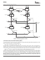
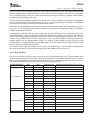
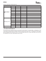
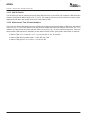
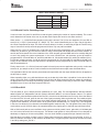
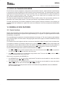
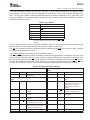
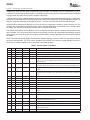
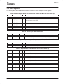
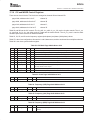
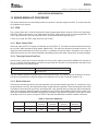
Table 4. Sum Selection Settings
Sum_sel setting
Asum
Bsum
0x0
0
0
0x43
a
b
0xA7
a+b
c+d
0xB7
a+b+c+d
c+d
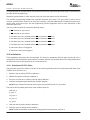
14.10.2 Sumin Port for Cascading Chips
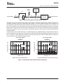
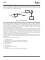
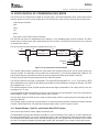
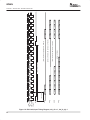
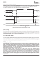
If sumin is active, the ports CO and DO are used as inputs (reducing the number of outputs available). The control
sumin determines the format of the sum in port data. Both outputs are forced to zero when sumin=0.
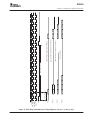
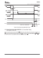
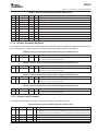
When sumin = 1, a 22-bit half-rate complex sumin path is formed. The 22 bits are mapped to CO and DO as
sumin[21..6] ≥ CO[15..0] and sumin[5..0] ≥ DO[15..10]. The I word is identified by the cic sync. Iflag is high when
the I word is expected as an input. The sumin-to-sumout delay is 14 clocks, so when Iflag is high the I word is being
output. Summers ib and qb would be programmed off since only one path is available.
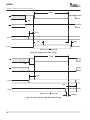
When sumin=2, CO[15..0] is passed as a 16-bit value to the sum node controlled by sum_ia. DO[15..0] is passed
to both sum_ib and sum_qa. This format is useful for using a sumin path with double rate real, full-rate complex, or
two full rate real channels. Due to the limitations of the 16-bit sumpath, gain and SNR need to be carefully analyzed
to see if they satisfy the system requirements. In the case of double rate, real summers qa and qb would be
programmed off, CO would add to ia, and DO would add to ib. CO should contain I(2k), while DO contains I(2k+1).
For full-rate complex summers, ib and qb would be programmed off, CO would add to ia, and DO would add to qa.
Finally, for two channels of full-rate real summers, qa and qb would be programmed off, while CO would add to ia
and DO would add to ib.
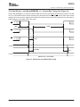
Finally, when sumin = 3, a 22-bit full rate sumin path is formed (most common application using sumin). In this case
summers ib, qa, and qb are all off. Gain is identical to the 22-bit half-rate complex case discussed above.
If an application calls for both a sumin port and transmit output hold, then the output hold should only be applied to
the last chip in a chain.
When cascading chips, sum_shift should be set only on the last chip in the chain, it should be 0 in the others. When
using a 22-bit sum chain, rounding should be set to 22 bits in all chips except the final one, where the rounding is
set appropriate to the next stage in processing (typically a DAC). Likewise, when using a 16-bit sum chain, rounding
should be set to 16 bits in all chips except the final one.
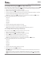
14.10.3 Sum Shift
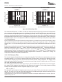
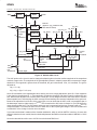
The four paths (ia, qa, ib, and qb) are then upshifted by 0−7 (sum_shift). For most applications, different channels
added together are independent and their powers should be added in a root-sum-square manner. For optimal
performance, gains should be optimized into the D/A, since that is the dominant source of noise. Once the desired
level into the DAC is found, gains for the rest of the signal processing chain can be derived. The hardwired gains
through the mixer, sumtree, and sumio are set to allow maximal signal growth. The sum shifter allows adjustment
in gain for other situations. The mixer allows 1 bit of growth (when one adds real x sin + imag x cos). The 2-bit growth
in the sum tree allows for four channels to be added together inside the chip. The 3-bit growth in the sumio (22-bit
mode) allows up to 8 GC5016 chips to be cascaded without any clipping prior to the final output shift and round.
With a 16-bit sumio path we can not afford to be so generous with bit growth. Hence, gains with a 16-bit data path
are 1 bit in the mixer and 2 bits in the sum tree. This allows a total growth of 3 bits (maximum of four channels for
absolutely no clipping or 64 users using RMS) − the user is still limited by signal power per channel in the DAC.
Note that there is no shifter on paths ic and id. These paths are used only when there is no summing, no sum_in,
and four channels are output (or two channels at double rate). The gain on paths ia and ib can be forced to match
ic and id by setting sum_shift to 3.
51