1
21135 HiLine Super manual:Layout 1
19/3/08
10:32
Page 3
HI-LINE Super RC
General Information
03
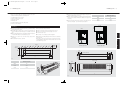
G The minimum installation height is 1.8m to the underside of
the unit.
2.0
Heating System Design
03
G The minimum clearance between the top of the unit and the
ceiling should be 50mm.
G The minimum side clearance is 150mm.
3.0
G Before proceeding with the installation, the heating system
design must be considered and the unit correctly sized to
meet the heat loss requirements of the room at normal fan
speed.
G The unit is supplied with an infra red remote control system,
giving automatic temperature control. Alternatively, the unit
can be run in manual mode, which allows manual switching
between the 3 fan speeds available to circulate ambient air.
G The HI-LINE Super RC should only be used on closed
circulation, two pipe, pump assisted central heating systems.
Unit Selection/Sizing
1.0
G This MYSON HI-LINE Super RC fan convector is designed for
wall-mounted installation with a maximum installation height
of 3m to the underside of the unit.
3.0
1.0
1.0 General Information
2.0
Contents
03
03
4.0
Location
4.0
This unit MUST NOT be installed in a bathroom or other similar high humidity area.
03
2.0 Heating System Design
5.0
6.0
Preparation
04
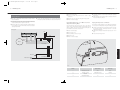
This fan convector must be fitted on a two pipe, pumped
circulation heating system.
For optimum fan convector heating performance the system
must be capable of providing sufficient hot water through the
heat exchanger. This means that:
Fixing
04
1. The minimum pipe size from boiler to fan convector must be
at least 22mm.
2. This unit is not suitable for use on microbore pipework.
7.0
Water Connections
05
8.0
Electrical Connection
06
9.0
Commissioning Procedure
07
4. The system water must be above 43°C for heating mode.
5. For heat pump applications - see Commissioning Procedure.
6. This unit is NOT suitable for one-pipe systems.
7. Optimum performance will require effective balancing of
the whole system.
8. This unit should NOT be used to replace a radiator in an
existing system unless an adequate flow of water can be
guaranteed.
3. Where the unit is fitted on to a system with other emitters a
separate circuit for the fan convector should be considered
to provide adequate water flow.
3.0 Unit Selection/Sizing
Heat output performance is given in the Technical Data section
of this manual. Outputs are shown for the 3 fan speeds,
however, it is important to size the unit to match the calculated
heat loss requirements of the room with the unit operating on
the low fan speed. The higher fan speeds are used in automatic
mode when the room temperature is significantly lower than the
preset temperature.
4.0 Location
10.0
Technical Data
08
11.0
Operating Instructions
09
12.0
Troubleshooting
10
13.0
Maintenance
11
G This HI-LINE Super RC unit may be fitted to any convenient
wall at a height from floor level that suits the application,
providing an unimpeded flow of warm air into the area to be
heated.
G The maximum distance from the underside of the unit to floor
level is 3m.
G The minimum distance to the underside of the unit is 1.8m.
G This unit should not be installed in locations with ceiling
heights greater than 3.5m.
G The unit should be mounted on a flat wall, and stud or
partition walls should be avoided to minimise the possibility
of noise transmission.