1
21135 HiLine Super manual:Layout 1
04
19/3/08
10:32
Page 5
HI-LINE Super RC
HI-LINE Super RC
5.0 Preparation
05
7.0 Water Connections
Before proceeding with the installation, unpack the carton
contents and check against the checklist below:
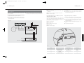
G Connect unit to system flow and return pipes using the two
22mm isolating valves (see fig. 3).
1. HI-LINE Super RC fan convector.
G Ensure system is flushed in accordance with recognised best
practice and a suitable inhibitor is added to the system as
necessary.
2. 22mm isolating valves (1 pair).
3. Instruction manual.
Dimensions (mm)
G Open valves fully, check pipe connections for leaks and vent
the heat exchanger - see Commissioning Procedure.
4. Warranty card.
Unit
A
29-20
1378
25-18
1168
5. Fixing kit (rubber mounts and cable gland).
6. Remote control handset.
CEILING
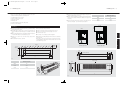
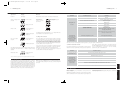
G Using the fixing dimensions below (see fig. 1), mark the fixing
hole positions on the wall.
Remove the outer casing as follows:
100 mm
6.0 Fixing
CEILING
G Remove 2 screws at each side securing outer cover.
G Remove the backing from the self-adhesive washers and place
on screws with adhesive side towards the point.
G Fit chassis on to mounting screws and tighten.
20 mm
G Remove the screw securing each side panel (see fig. 2).
G Drill and plug the wall for No. 8 x 40mm round head wood
screws ensuring that the wall plugs are suitable for the wall
type.
Note: Before proceeding with pipe-work connections check that
the unit is level.
G Press adhesive washers to the wall.
When water connections and electrical connections have been
completed and the unit has been vented, fit the outer cover and
secure with fixing screws.
6.0
G Tighten the screws into the wall leaving about 9mm
projecting.
5.0
G Lift off the outer case.
150 min
each
side
a) Rear pipe entry
b) Top pipe entry
82
69
55
117
55
Mains cable entry
92
21
275
144
77
20 min
100 max
7.0
Ceiling
23
53
201
63
103
A
Fig. 1
View on arrow
29-20
1360
25-18
1150
108
A
275
Unit
128
203
Dimensions (mm)
A
Fig. 2 Case fixing screw positions
Fig. 3