1
8W/A/ S
®
MODEL NUMBER 917.258990
OWNER'SMANUAL
° Assembly
o Operation
Customer Responsibilities
o Service and Adjustments
Repair Parts
CAUTION:
Read
and follow
all safety
rules and instructions
before
operating
this equipment.
FOR CONSUMER ASSISTANCE HOT LINE, CALL THIS TOLL FREE NUMBER: 1-800-659-5917
II
I
M
SAFETY
Safe Operation
PracticesRULES
for Ride-On Mowers
IMPORTANT:
THIS CUTTING MACHINE IS CAPABLE OF AMPUTATING
HANDS AND FEET AND THROWING OBJECTS.
FAILURE TO OBSERVE THE FOLLOWING SAFETY INSTRUCTIONS
COULD RESULT IN SERIOUS INJURY OR DEATH.
I.
.
°
•
•
•
,,
•
,,
•
.
°
.
•
•
•
II.
GENERAL
OPERATION
Read, understand, and follow all instructions in the manual
and on the machine before starling.
Only allow responsible adults, who are familiar with the
instructions, to operate the machine.
Clear the area of objects such as rocks, toys, wire, etco,
which could be ptcked up and thrown by the blade.
Be sure the area is clear of other people before mowing. Stop
machine if anyone enters the area..
Never carry passengers.
Do not mow in reverse unless absolutely necessary Atways
look down and behind before and while backing.
Be aware of the mower discharge direction and do not point
it at anyone° Do not operate the mower without either the
entire grass catcher or the guard in place.
Slow down before tuming_
Never leave a running machine unattended. Always turn off
blades, set parking brake, stop engine, and remove keys
before dismounting°
Turn off blades when not mowing
Stop engine before removing grass catcher or unclogging
chute.
Mow only in daylight or good artificial light.
Do not operate the machine while under the influence of
alcohol or drugs.
Watch for' traffic when operating near or crossing roadways_
Use extra care when loading or unloading the machine into
a trailer or truck.
SLOPE
OPERATION
Slopes are a major factor related to loss-of-control and
tipover accidents, which can result in severe injury or
death° All slopes require extra caution. If you cannot back
up the slope or if you feel uneasy on it, do not mow it.
DO:
•
Mow up and down slopes, not across
•
Remove obstacles such as rocks, tree limbs, etc.
•
Watch for holes, ruts, or bumps.
Uneven terrain could
overturn the machine. Ta// grass can hide obstac/es.
•
Use slow speed_ Choose a low gear so that you wUlnot have
to stop or shift while on the slope°
°
Follow the manufacturer's recommendations for wheel
weights or counterweights to improve stability.
•
Use extra care with grass catchers or other attachments_
These can change the stability of the machine,
•
Keep all movement on the slopes s/owand gradual Do not
make sudden changes in speed or direction
=
Avoid starting or stopping on a slope° tf tires lose traction,
disengage the blades and proceed slowfy straight down the
slope.
III. CHILDREN
Tragic accidents can occur' if the operator is not alert to the
presence of children,
Children are often attracted to the
machine and the mowing activity.
Never assume that
children will remain where you last saw them.
°
Keep children out of the mowing area and under the watchful
care of another responsible adult.
•
Be alert and turn machine off if children enter the area_
•
Before and when backing, look behind and clown for small
children.
,,
Never carry children. They may fall off and be seriously
injured or interfere with safe machine operation°
=
Never allow children to operate the machine
•
Use extra care when approaching blind corners, shrubs,
trees, or other objects that may obscure vision.
IV. SERVICE
Use extra care in handling gasoline and other fuels. They are
flammable and vapors are exptosi'veo
Use only an approved container.
Never remove gas cap or add fuel with the engine
running. AEiowengine to cool before refueting_ Do not
smoke.
Never refuel the machine indoors.
Never store the machine or fuel container inside where
there is an open flame, such as a water heater.
°
Never run a machine inside a closed area.
e
Keep nuts and bolts, especially blade attachment bolts, tight
and keep equipment in good condition.
°
Never tamper with safety devices_ Check their proper
operation regularly,.
o
Keep machine free of grass, leaves, or other debris build-up.
Clean oil or fuel spillage. Allow machine to cool before
storing
°
Stop and inspect the equipment if you strike an objecL
Repair, if necessary, before restarting.
Never make adjustments or repairs with the engine running.
a
Grass catcher components are subject to wear, damage, and
deterioration, which could expose moving parts or allow
objects to be thrown. Frequently check components and
replace with manufacturers recommended parts, when necessaryo
Mower blades are sharp and can cut. Wrap the blade(s) or
wear gloves, and use extra caution when servicing them.
Check brake operation frequently
Adjust and service as
required.
ii
i_Li IHl'l
|
Look forthls symbolto
point out Important
safety
CAUTIONIIIprecautions.
BECOME
SAFETY IS INVOLVED.
It
ALERTIIt
ii
DO NOT:
.
Do not turn on slopes unless necessary, and then, turnslowly
and gradually downhill, if possible.
°
Do not mow near drop-offs, ditches, or embankments. The
mower could suddenly tum over if a wheel is over the edge
of a cliff or ditch, or if an edge caves in.
•
Do not mow on wet grass. Reduced traction could cause
sliding.
•
Do not try to stabilize the machine by putting your foot on the
ground.
.
Do not use grass catcher on steep slopes°
i
!
means
YOUR
I
iii
ii
...............................
i
i1,1,1
CAUTION: Always disconnect spark plug
wire and place wire where it cannot contact
spark plug in order to prevent accidental
starting when setting up, transporting,
adjusting or making repairs.
iiiiiiiiiiiiiiii
I
..................
A WARNING A
The engine exhaust from this product contains
chemmais known to the State of California to
cause cancer, birth defects, or other reproductive harm.
iiiii
,i iiiiiiii
ii
i ,,i,,11,
_
'_
PRODUCT
CONGRATULATIONS
on your purchase of a Sears
Tractor° It has been designed, engineered and manufactured to give you the best possible dependability and
performance..
Should you experience any problem you cannot easily
remedy, please contact your nearest Sears Authorized
Service Center/Department
Department
We have competent, well-trained technicians and the proper tools to
service or repair this tractor,
Please read and retain this manual,-. The instructions will
enable you to assemble and maintain your tractor properly
Always observe the "SAFETY RULES".
MODEL
NUMBER
917.258990
SERIAL
NUMBER
DATEOFPURCHASE
THEMODELANDSERIALNUMBERSWILLBEFOUND
ON A PLATE UNDER THE SEAT,
YOU SHOULD RECORD BOTH SERIAL NUMBER AND
DATE OF PURCHASE AND KEEP IN A SAFE PLACE
FOR FUTURE REFERENCE.
MAINTENANCE
AGREEMENT
RESPONSIBILITIES
•
Read and observe the safety rules.
.
Follow a regular schedule in maintaining, caring for and
using your tractor.
•
Follow the instructions under"Customer ResponsibitF
ties" and "Storage" sections of this owner's manual..
LIMITED TWO YEAR WARRANTY
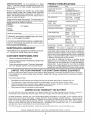
HORSEPOWER:
20.5
GASOLINE CAPACITY
AND TYPE:
35 GALLONS
UNLEADED REGULAR
OIL TYPE (API-SF/SG):
SAE IOW30 (above 32°F)
SAE 5W-30 (below 32°F)
OIL CAPACITY:
W! FILTER: 4 2 PINTS
WiO FILTER: 37 PINTS
SPARK PLUG:
(GAP: 030")
CHAMPION RCI2YC
VALVE CLEARANCE:
NOT ADJUSTABLE
GROUND SPEED (MPH):
FORWARD: 5 8
REVERSE: 2 1
TIRE PRESSURE:
FRONT: t4 PSi
REAR:
10 PSi
CHARGING SYSTEM:
15 AMPS @3600 RPM
BATTERY:
AMP/HR:
35
MIN CCA:
280
CASE SIZE: U1R
BLADE BOLT TORQUE:
30-35 FT LBS
WARNING:
This tractor is equipped with an internal
combustion engine and should not be used on or near any
unimproved forest-covered, brush-covered or grass-covered land unless the engine's exhaust system is equipped
with a spark arrester meeting applicable local or state taws
(if any). If a spark arrester is used, it should be maintained
in effective working order by the operator
In the state of California the above is required by law
(Section 4442 of the California Public Resources Code).
Other states may have similar laws. Federal laws apply on
federal lands A spark arrester for the muffler is available
through your nearest Sears Authorized Service Center/
Department (See REPAIR PARTS section of this manual).
A Sears Maintenance Agreement is available on this product.. Contact your nearest Sears store for details..
CUSTOMER
SPECIFICATIONS
ON CRAFTSMAN
RIDING EQUIPMENT
For two (2) years fromthe date of purchase, if this Craftsman Riding Equipmenl is maintained, lubricated and tuned up according
to Ihe instructions in the owneCs manual, Sears will repair or replace, free o! charge, any parts found to be defective in material
or workmanship
This Warranty does not cover:
o
•
•
Expendable items which become worn during normal use, such as blades, spark plugs, air cleaners, belts, efc
Tire replacement or repair caused by punctures from outside objects, such as nails, thorns, stumps, or glass
Repairs necessary because of operator abuse, negligence,
improper storage or accident or the failure to maintain the
equipment according to the instructions contained in the owner's manual
Riding equipment used for commercial or rental purposes
LIMITED
90 DAY WARRANTY
ON BATTERY
For ninely (90) days from date of purchase, it any battery included with lhis riding equipment proves r.]efective{n material or
workmanship and our testing determines the batterywill not hold a charge. Sears will replace lhe baltery al no charge
tN-HOME
WARRANTY
SERVICE
ON YOUR CRAFTSMAN
RIDING
EQUIPMENT
IS AVAILABLE
AT NO-CHARGE
DAYS FROM THE DATE OF PURCHASE
PLEASE
CONTACT
YOUR NEAREST
SERVICE
CENTER
AFTER
FOR 30
30 DAYS
FROM THE DATE OF PURCHASE,
WARRANTY
SERVICE
IS AVAILABLE
BY TAKING YOUR CRAFTSMAN
RIDING EQUIPMENT TO YOUR NEAREST
SEARS SERVICE
CENTER
(IN-HOME
WARRANTY
SERVICE
WILL STILL BE AVAILABLE
AFTER 30 DAYS FROM THE DATE OF PURCHASE
BUT A STANDARD
TRIP CHARGE
WILL APPLY ) THIS WARRANTY
APPLIES ONLY WHILE THIS PRODUCT
tS IN THE UNITED STATES
This Warranty
gives you specilic
legal
rights, and you may also have other
rights which
may vary from stale
SEARS. ROEBUCK AND CO. D/8!7 WA. HOFFMAN ESTATES. IL 60179
t
3
,i
to slate
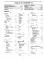
"TABLE OF CONTENTS
SAFETY RULES ............................................................
2
PRODUCT SPECIFICATIONS ...................................... 3
CUSTOMER RESPONSIBILITIES ..................... 3, 17-20
WARRANTY ..................................................................
3
TRACTOR ACCESSORIES .......................................... 5
ASSEMBLY ..............................................................
7-10
OPERATION ............................... :..T........ :............... 11-16
aNDEX
E
A
Accessories
...................................
MAINTENANCE SCHEDULE ......................................
17
SERVICE AND ADJUSTMENTS ............................ 21-27
STORAGE ...................................................................
28
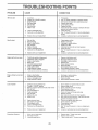
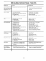
TROUBLESHOOTING. ...........................................
29-30
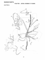
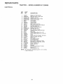
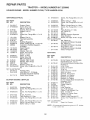
REPAIR PARTS - TRACTOR ................................. 32-49
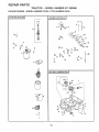
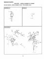
REPAIR PARTS- ENGINE .................................... 50-59
PARTS ORDERING/SERVICE ................ BACK COVER
5
Adjustments:
Brake ...........................................
23
Carburetor .................................
27
Clutch Pulley .............................
23
Gauge Wheels .....................
14
Mower
Front-To-Back
.....................
22
Side-To-Side ..........................
21
Throttle Control Cable ............... 27
Air Filter, Engine ...............................
20
Air Screen, Engine ................................ 19
Assembly ................................
740
Operation
11-16
Operating Mower ......................................14
Options:
Accessories ............................
5
Spark Arrester ..................................
3,40
........................................
Electrical:
interlocks and Relays ................. 26
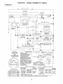
Schematic ..............................
31
Wiring Diagram ........................... 32
Engine:
Air Filter ..........................
20
Air Screen ..............................
19
Cooling Fins i ........................
19
Oil Change ....................
17
Oil Level .....................
17
Oil Type .............................
13,17
Preparation .............................
t5
Repair Parts .....................
48-59
Starting ..............................
15
Storage ...........................
28
P
Parking Brake ..................................
13
Parts Bag ...............................................
6
Pr._s, Replacement/Repair
............ 32-49
Product Specifications ............................ 3
R
Repair Pads
..............................
B
Battery:
Charging ..............................
Cleaning ....................................
Starling with Weak Battery ........
Storage .......................................
Terminals .............................
Bett:
Motion Drive
Removal/Replacemenl
............
Mower Drive
Removal/Replacement
..........
Mower Blade Drive
Removal/Replacement
........
Blade:
Sharpening .........
Replacement ..............................
Brake Adjustment ............................
22
Filter:
Air Filter _............
Fuel ......................
Oil ......................................
Fuel:
Storage ...............................
Type .............................
Fuse ............................
22
23
18
18
23
C
Carburetor Adjustment ..................
27
Clutch Pulley
..........................
23
Controls, Tractor ......................
12
Customer Responsibilities ........
17-20
Engine:
Air Filter ..................
20
Air Screen ....................
19
Cooling Fins .................
19
Engine Oil .........
15,19
Fue! Filter ...........
20
Spark Plug(s)
20
Tractor:
Batlery.
18
Blade ..........
18
Lubrication Chart ........
t7
Maintenance Schedule
...... 17
Tire Care
. 8.I8.25
Transaxle
:
19
Cutting Height Mower
S
F
8
20
25
28
18
13
20
20
20
28
15
26
H
Headlights ...............
Hood Removal/Installation
26
................ 26
L
Leveling Mower Deck .................
Lubrication:
Chart .........................................
Engine ...........................
Maintenance Schedule
Mower:
Adjustment, Front-to-Back
Adjustment, Side-to-Side
Blade Replacement
Blade Sharpening
Cutting Height
installation .........
Operation .....
Removal ....
Mowing Tips
Muffler ..........
Spark Arrester
21
17
t9
17
22
2t
18
18
13
21
14
21
16
20
340
O
Oil:
Co_d Weather Conditions
Engine
4
Safety Rules .........................................
Seat .....................................................
2
8
Service and Adjustments ............... 21-27
Carburetor ...................................
27
Clutch Pulley .................................. 23
Fuse ................................
26
Hood Removal/Installation .......... 26
Motion Drive Belt
Removal/Replacement
......
22
Mower Drive Belt
Removal/Replacement
......... 22
Mower Blade Drive Bett
Removal/Replacement
.......... 23
Mower Adjustment
Front-to-Back
22
Side-to-Side .......................
21
Mower Removal/Installation ......... 21
Tire Care ........................
8,18,25
................................
M
Storage
32-49
1519
17
28
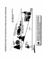
Slope Guide Sheet .......................
Spark Plug(s)
..........................
Specifications
............
Starting the Engine ..........................
Steering Wheel .....................
Slopping the Tractor
...................
Storage
.............................
63
20
3
15
7.24
13
28
T
Throttle Control Cable Adjustment
27
Tires
..................
8.18.25
Troubleshooting Chart
......
Transaxle ............................
29-30
19
W
Warranty
Wiring D_agram
Wiring Schemahc
........
...................
3
32
31
I
ii,i,u..,..i,
,,,,,,,,,,
............................
ACCESSORHES
U.l,lUlUl
These accessories
Most Sears stores
AND A'['TACHMENTS
i i i
...........................................
and attachments
can order these
were available
through most Sears retail oullets and service centers
items for you when you provide the model number of your tractor
ENGINE
when
the tractor
was
Ill
purchased
MAINTENANCE
SPARK PLUG
GAS CAN
ENGtNE OIL
FUEL STABILIZER
AIR FILTER
BLADES
t
BELTS
T
PERFORMANCE
Sears offers a wide variety of attachments
that fit your tractor Many of these are listed below with brief explanations
of how they can help
you This Iist was current at the time of publication;
however,
it may change in future years - more attachments
may be added, changes
may be made in these attachments,
or some may no longer be available or fit your modei
Contact
your nearest
Sears store for the
accessories
and attachments
that are available
for your tractor,
Most of these attachments
attaching
and detaching.
do not require
additional
hilches or conversion
AERATOR promotes deep root growth for a healthy lawn. Tapered
2 5-inch steel spikes mounted on 10-inch diameter discs puncture
holes in soil at close intervals to let moisture soak in Steel weight tray
for increased penetration
BUMPER
protects
front end of tractor from damage
CARTS make hauling easy Variety oJsizes available, ptus accessories such as side panel kits, tool caddy, cart cover, protective mat and
dolly
CORING AERATOR
takes small plugs out of soil Io allow moisture
and nutrients to reach grass roots 36-inchswath
24hardenedsteel
codng tips 150 lb capacity weight tray.
DISC HARROW has 2 gangs of 4 steel blades that angle from 10 to
20 degrees, 40 inches wide Can hook 2 units in tandem
(Requires
sleeve hitch )
DOZER BLADE removes snow; grades
inches wide, 1'_ _nches high, clears 44-inch
lift control fev.er for operator ease Spring
uneven pavement; buiRqn float for blade
Revers;b]e, repSaceabte scraper bar (Use
weights and/or rear drawbar weight )
EASY
OIL DRAIN
VALVE
makes
dirt, sand and gravel 48
path when angled Master
trip for snow removal on
to follow ground contour,
wilh tire chains and wheel
oil changes
deck to reduce
GANG HITCH lets you tow 2 or 3 pull-behind
attachments
at
once, such as sweepers,
dethatchers,
aerators (not for use with
rollers, carts or other heavy attachments)
MULCH RAKF-JDETHATCHER
loosens soil and flips thatch and
matted leaves to lawn surface for easy pickup. Twenty spring tine
teeth Useful to prepare bare areas for seeding. Available for front or
rear mounting,
HIGH PERFORMANCE
REEL-ACTION
SPRING
TtNE DETHATCHER
covers 36-inch wide palh and tosses thatch into
large hopper
Mounts behind tractor
PLOW turns soil 6 inches deep, cuts lO-inch furrow Crank adjust _
ment controls depth 3-position yoke sets width. Heavy steel landside
for straight furrowing
(Requires sleeve hitch
RAMP TOPS AND FEET _et you load and unload tractor
pickuplruck
Usewitn2xSor2x
tO lumber
from a
REAR GRADER BLADEis42incheswideand
operatedfromdriver's
seat Reversible steel blade can be angled at 30 degrees lor grading
Reverses for pushing snow backwards
(Requires sleeve hilch )
ROLLER
for smoother
lawn surface.
364nch wide. 18qnch diameter
wa_er-tight drum holds up to 390 Ibs o{ we_gtl_ Rounded edges
prevent harm to lud Adiustable scraper automatically cleans drum
that do are indicated)
and are designed
for easy
SLEEVE CULTIVATOR
is 43 inches wide. Prepares ground for
seeding, hetps weed control. Steel frame holds 5 adjustab{e sweeps,
Adjusts vertically, horizontally
(Requires steeve hitch ) Optional
accessory:
steel furrow opener for wider openings for potatoes,
corn, and other deep-seeded
crops
SLEEVE HITCH for use with master lift system
uncouples
Single pin couples/
SNOWTHROWER
has 424nch swath
Drum-type auger handtes
powdery and weVheavy snow Mounts easily with simpte pin arrangement. Discharge chute adjusts from tractor seat
6-inch diameter
spout discharges snow I0 to 50 feet Lift controlled
at tractor seat
(Use with chains and wheel weights and/or rear drawbar weight )
SPRAYERS use 12-volt DC electdc motor that connects to the tractor
battery or other 12-vo_t source
includes booms {or automatic
spraying and hand held wand {or spot spraying
Wand has adjustable
spray pattern
For applying herbicides, insecticides, fungicides and
liquid fertilizers
SPREADERtSEEDERS
make seeding, ledilizing, and weed killing
easy Broadcast spreaders are also useful tot granutar de-icers and
sand
SWEEPERS
easier, faster
FRONT NOSE ROLLER canters in front of mower
chances of "scalping" on uneven terrain
kits (those
let you col_ecf grass clippings
and leaves
TILLER has 8 hp engine tn prepare seed beds. cultivate, and compost
garden residue Chain-drivelransmission
Six11-inchdiameterone
piece heat-trealed
steel tines. Tills 30-inch path (Requires sleeve
hitch ) Or use 5 hp tow-behind TILLER with 36-inch swath to prepare
seed beds, cultivate and compost garden residue. Ti#er has its own
buiIFin lift and depth control system and does NOT require a sleeve
hitch Fits any lawn, yard or garden traclor
Simply hook op to the
tractor drawbar and go! Optional accessories
!or 5 hp tiller convert
unit {or delhatching,
aeraling, hilling
without tools
TIRE CHAINS are heavy duty; closely spaced
give smooth ride outstanding traction
extra-large
cross links
TRACTOR CAB has heavy duty vinyl fabric over tubular steel frame.
ABS plastic top; clear plastic windshie{d offers 360 degree visibility
Hinged metal doors with catch
Keeps operator warm and dry
Remove vinyl sides and windshields
for use as sun protector ip
summer.
Optional
accessories
include:
tlntedltempered
solid
safety grass windshield with hand operated wider: 12-vott amber
caution light lot mounting on cab top
VACS for powerful collection of heavy grass clipongs and _eaves
Optional wand attachment
lo pick up debris tn hardqo-reacn
c,laces
VAC/CHIPPER
includes a ch_pDer-shredder
WEfGHT BRACKET lot drawbar for snow removal applications
Car
be mounted on front of traclor for p]owinq aDpl_cahons
Uses (I i 55
Ib weight
WHEEL
removal
WEIGHTS for rear wheeJs prowc_e needed tract_or', for snow
or dozing l_eavy maIenats
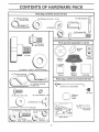
CONTENTS
OF HARDWARE
Parts Bag contents
ii ,n nnl
i,,nl
i n
PACK
shown full size
i
f
(4) Retainer Spr)ngs
(4) Adjusting Bar
(4) Washers 3/8 x 3/4 x 14 Ga
(4) Clevis Pins
(4) Wheels
@
i
(4) Shoulder Bolt
__
(4) Locknut 3/8-16
Parts packed separately
(t) Shoulder
Bolt 5/I6-t8
in carton
Mulcher
Plate
(1) Knob
Video
Cassette
Steering
Wheel
Seat
(I) Washer
17/32 x 1-3/16 x 12 Gauge
(3) RetainerSprings
_\
Manual
Steering
Sleeve
Parts bag contents
(double loop) _l_.,_
(4) Retainer Springs
(single loop)
_(2)
[
I
{
I
I
I
I
I
Parts
Bag
not shown full size
Front Link Assemblies
(2) Keys
(2) Screws
(2) Lock Washers
#10 x 5/8
Steering
Wheel
Insert
#10
f-1
(2) Weld Nuts #10 _
(2) Washers
1
3/16 x 3/4 x 16 Gauge
,ulnu iii1,1lU
iii
(2} Hex Bolts 1/4-20 x 3/4
.-ri
i i, nll,n n
(2) Hex Nuts_'k
i/4-20
Z't (7
Assembiys
b
J
Slope Shee[
LY
:
i i H H,mHI H,,,,,=,m=
,==l =l I m
=
.......................
Your new tractor has been assembled at the factory with exception of those parts left unassembted for shipping purposes.
To ensure safe and proper operation of your tractor all parts and hardware you assemble must be tightened securely Use
the correct tools as necessary to insure proper tightness
TOOLS
REQUIRED
FOR ASSEMBLY
A socket wrench set will make asserhbiy easier
wrench sizes are listed.,
(2) 7/16" wrenches
(1) Tire pressure gauge
(1) 9/16" wrench
(1) Utility knife
(1) 1/2" wrench
(1) 3/4" socket w/drive ratchet
Pliers
Phillips Screwdriver
STEERING
_
INSERT
_
FLAT
WASHER
STEERING
WHEEL
t
TO REMOVE TRACTOR FROM CARTON
CARTON
•
Remove all accessible loose parts and parts cartons
from carton (See page 6)
o
Cut, from top to bottom, along lines on all four corners
of carton, and lay panels flat..
o
Remove mower and packing materials_
,,
Check for any additional loose parts or cartons and
remove..
HEX BOLT
WASHER
When right or left hand is mentioned in this manual, it
means when you are in the operating position (seated
behind the steering wheel),
UNPACK
WHEEL
Standard
STEER,NG
i
STEERING
SHAFT
ADAPTER
STEERING
SLEEVE
/
/
I
_
l
lf
I
l//
/
/
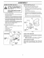
BEFORE ROLLING TRACTOR OFF SKID
FIG. !
ATTACH
STEERING
WHEEL
(See Fig. 1)
°
Remove hex bolt, lock washer and large flat washer
from steering shaft.
°
Position front wheels of the tractor so they are pointing
straight forward
•
Slide steering sleeve over steering shaft.
•
Position steering wheel so cross bars are horizontal
(left to right) andslide onto steering wheel adapter
o
Secure steering wheel to steering shaft with hex bolt,
lock washer and large flat washer previously removed•
Tighten securely
=
Snap steering wheel insert into center of steering
wheel.
TO ROLL TRACTOR OFF SKID (See Operation section
for location
and function
of controls)
,
Press lift lever plunger and raise attachment lift lever to
its highest position
o
Release parking brake by depressing
pedal
°
Place freewheel control in freewheeling position to
disengage transmission (See "TO TRANSPORT" in
the Operation section of this manual)
Roll tractor backwards off skid
°
,, Remove protective plastic from tractor hood and grill.
IMPORTANT: CHECK FOR AND REMOVE ANY STAPLES
IN SKID THAT MAY PUNCTURE TIRES WHERE TRACTOR
IS TO ROLL OFF SKID
7
clutch/brake
CONNECT BATTERY (See Fig. 2)
i
INSTALL
SEAT (See Fig. 3)
i
Adjust seat before tightening adjustment knob
nals. Before connecting battery, remove
metalDo bracelets,
wristwatch
CAUTION:
not short battery
termibands, rings, etc.
_)
Positive terminal must be coJmected
first to prevent sparking from accidental grounding.
o
Lift hood to raised position.
-
Open terminal access doors, remove terminal protective caps and discard
°
tf this battery is put into service after month and year
indicated on label (label located between terminals)
charge battery for minimum of one hour at 6+10 amps
.
First connect RED battery cable to positive (+) battery
terminal with hex bolt, flat washer, tock washer and hex
nut as shown.. Tighten securely.
o
°
•
Remove cardboard packing on seat pan.
Place seat on seat pan and assemble shoulder boil
°
Assemble adjustment knob and flat washer tooseiy
Dn ,lot tighten
°
Tighten shoulder bolt secureiy
°
°
Lower seat into operating position and sit on seat.
,
Slide seat until a comfortable position is reached which
allows you to press clutch/brake pedal all the way
down.
,
Get off seat without moving its adiusted position
,,
Raise seat and tighten adjustment knob securely
SEAT
S
SEAT PAN
Connect BLACK groundingcabte to negative (-) battery
terminal with remaining hex bolt, flat washer, lock
washer and hex nut.. Tighten securely
Close terminal access doors.
SHOULDER
BOLT
S
Use terminal access doors for:
Inspection for secure connections
ware)+
+
Inspection for corrosion.
o
Testing battery°
o
(to tighten hard-
FLAT
WASHER
ADJUSTMENT
KNOB
Jumping (if required).
Periodic charging.
HEX NUT
LOCK
WASHER
FIG. 3
FLAT
WASHER
DISCARD TERMINAL
PROTECTIVE CAPS
HEX
BOLT
CHECK TIRE PRESSURE
The tires on your tractor were overinflated at the factory for
shipping purposes Correct tire pressure is important for
best cutting performance
TERMINAL
ACCESS
DOOR
" +;
,
__`
+
:
POSITIVE
(RED)
CABLE
J
'
!L. I
+_
NEGATIVE
(BLACK)
CABLE
....
FIG, 2
Reduce tire pressure to PSI shown in "PRODUCT
SPECIFICATIONS" on page 3 of this manual
CHECK
BRAKE
SYSTEM
After you Iearn how to operate your tractor, check to see
that the brake is properly adjusted
See "TO ADJUST
BRAKE" in the Service and Adiustments section of this
manual.
ASSEMBLY
INSTALL
MOWER
AND
DRIVE
BELT
o
Place the suspension arms on inward pointing deck
pins, If necessary, rock and raise front of mower to
align deck pins with the holes in suspension arms
Retain with double loop retainer springs with loops
down as shown
•
Connect anti-sway bar to chassis bracket under left
footrest and retain with double loop retainer spring.
,,
Turn height adjustment knob clockwise
slack from mower suspension
•
Raise deck to highest position,
,,
Adjust gauge wheels before operating mower as shown
in the Operation section of this manual,
(See Figs. 4 and 7)
Be sure tractor is on level surface and mower suspension
arms are raised with attachment lift control Engage parking brake
,
Cut and remove ties securing anti-sway bar and belts.
Swing anti-sway bar to left side of mower deck.
=
Slide mower under tractor with discharge guard to right
side of tractor.
IMPORTANT: CHECK BELT FOR PROPER ROUT[NGIN
ALL MOWER PULLEY GROOVES. INSTALL BELT INTO
ELECTRIC CLUTCH PULLEY GROOVE
°
Install one front link in top hole of the L.H. front mower
bracket and L H front suspension bracket Retain with
two single loop retainer springs as shown
,
Install second front link in R. H front suspension bracket
only and retain with single loop retainer spring as
shown,
o
Slide right side of mower back and install link in top hole
of R H front mower brackeL Retain with single loop
retainer spring as shown,
o
Turn height adjustment knob counterclockwise
stops
,
Lower mower linkage with attachment lift control,,
CHASSIS
BRACKET
DOUBLE LOOP
RETAINER
SPRING (Outward
pulnt[ng deck pins)
CHECK
MOWER
to remove
LEVELNESS
For best cutting results, mower should be properly leveled.
See "TO LEVEL MOWER HOUSING" in the Service and
Adjustments section of this manual
CHECK
BELTS
FOR
PROPER
POSITION
OF
See the figures that are shown for replacing motion, mower
drive, and mower blade drive belts in the Service and
Adjustmentssectionofthis
manual, Veritythatthebelts
are
routed correctly
until it
ELECTRIC
CLUTCH
PULLEY
FRONT
SUSPENSION
BRACKETS
SUSPENSION
ARMS
FRONT
MOWER
BRACKET
--
FRCNT
LINK
SINGLE LOOP
RETAINER
SPRINGS
GAUGE
WHEEL
DOUBLE
LOOP
RETAINER
SPRING
ALL
ANTI-SWAY
BAR
I
/
/
/
DISCHARGE
GUARD
IDLER
PULLEY
9
ASSEMBLY
INSTALL
MULCHER
PLATE
(See Figs. 5 and 6)
•
Install two latch hooks to mulcher plate using screw,
washer, lock washer, and weld nut as shown.
NOTE: Pre-assemDle weld nut to latch hook by inserting
weld nut from the top with hook pointing dowrL
o
Tighten hardware securely,
°
o
°
Raise and hold deflector shield in upright position,
Place front of mulcher plate over front of mower deck
opening and slide into place, as shown.
Hook front latch into hole on front of mower deck,
•
Hook rear latch into hole on back of mower deck
LATCH
HOOKS
CAUTION: Do not remove discharge
guard from mower. Raise and hold
guard when attaching mulcher plate
and allow it to rest on plate while in
operation.
FIG. 6
/ CHECKLIST
TO CONVERT
DISCHARGING
TO BAGGING
BEFORE YOU OPERATE AND ENJOY YOUR NEW
TRACTOR, WE WISH TO ASSURE THAT YOU RECEIVE
THE BEST PERFORMANCE AND SA TISFA C TION FROM
THIS QUALITY PRODUCT
OR
Simply remove mulcher plate and store in a safe place.
Your mower is now ready for discharging or installation of
optional grass catcher accessory_
PLEASE REVIEW THE FOLLOWING CHECKLIST:
,/" All assembly instructions have been completed..
NOTE: It is not necessary to change blades. The mulcher
blades are designed for discharging and bagging also.
WELD NUT
FROM THE TOP
HOOK POINTS
DOWN
\
z
LOCK
WASHER
SCREW
/
No remaining loose parts in carton.
,/
Batteryis ploperly prepared and charged.
! hour at 6 amps)
,/
Seat is adjusted comfortably and tightened securely,
7
All tires are property inflated, (For shipping purposes,
the tires were overinfiated at the factory).
v"
Be sure mower deck is properly leveled side-to-side/
front-to-rear for best cutting results (Tires must be
properly inflated for leveling)..
Check mower and drive belts. Be sure they are routed
properly around pulleys and inside all belt keepers.
LATCH
HOOK
,/
WELD_,
NUT --
,/
LATCH
HOOK
Check wiring. See that all connections ate still secule
and wires are propedy clamped
v"
Before driving tractor, be sure freewheel control is in
drive position
WHILE LEARNtNG HOW TO USE YOUR TRACTOR, PA Y
EXTRA ATTENTION TO THE FOLLOWING IMPORTANT
ITEMS.
LOCK
WASHER
WASHERS
MULCHER
PLATE
(Minimum
_SCREW
v'
v"
FIG. 5
v'
10
Engine oil is at proper level
Fuel tank is filled with fresh, clean, regular' unleaded
gasoline
Become familiar with all controls - their location and
function Operate them before you start the engine
v"
Be sure brake system is in safe operating condition
,/
It is important Io purge lhe transmission before operating your tractor for the first time Follow proper starting
and transm_ssionpurging instructions (See "TO START
ENGINE" and "PURGE TRANSMISSION" in Qoera.
{tonsection of this manual)
i,i,
iiii
iiiiiiiiiiiiii
i ii ,, ,,
OPERATION
These symbols may appear on your tractor or in literature supplied with the product
Learn and understand their meaning,
BATTERY
CAUTION OR
WARNING
REVERSE
FORWARD
FAST
SLOW
ENGINE ON
ENGINE OFF
OIL PRESSURE
CLUTCH
LIGHTS ON
LIGHTS OFF
PARKING BRAKE
LOCKED
UNLOCKED
\
FUEL
CHOKE
REVERSE
m
"%
MOWER HEIGHT
DIFFERENTIAL
LOCK
NEUTRAL
HIGH
LOW
PARKING BRAKE
÷
MOWER LIFT
ATTACHMENT
CLUTCH ENGAGED
ATTACHMENT
CLUTCH DISENGAGED
HYDROSTATIC
DANGER, KEEP HANDS AND FEET AWAY
IGNITION
FREE WHEEL
(Hydro Models onlyi
11
OPERATmON
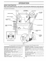
KNOW YOUR TRACTOR
READ THIS OWNER'S
MANUAL
AND SAFETY
RULES BEFORE
OPERATING
YOUR TRACTOR.
Compare the illustrations with your tractor to familiarize yourself with the tocation of various controls and adjustments
this manual for future reference
ATTACHMENT
CLUTCH SWITCH
AMMETER
_ - --
CHOKECONTROL
THROTTLE
Save
LIGHT SWITCH
LiFT LEVER
PLUNGER
_
@
CONTROL
CLUTCH/BRAKE
PEDAL
LIFT LEVER
HEIGHTADJUSTMENT
KNOB
IGNITION SWITCH
PARKING
LEVER
1
BRAKE
MOTION
CONTROL
LEVER
APPROXo
SPEEDS:
3 MPH
FREE WHEEL CONTROL
FIG. 7
Our tractors conform to the safety standards of the American National Standards Institute,
A'IR'ACH MENT CLUTCH SWITCH - Used to engage mower
blades or other attachments mounted to your tractor
FREEWHEEL CONTROL - Disengages transmission for
pushing or slowly towing the tractor with the engine off
LIFT LEVER- bsed to raise and lower mower deck or other
attachments mourned to your tractor
IGNITION SWITCH - Used to start and stop the engine
CLUTCH/BRAKE
PEDAL - Used for declutching
braking the tractor and starting the engine
6)
AMMETER - Indicates battery charging (+) or discharging
and
LIFT LEVER PLUNGER - Used to release attachment lift
lever when changing its position
MOTION CONTROL - Selects the speed and direction of
tractor
PARKING BRAKE LEVER* Locks clutch/brake pedat tnto
the brake position
CHOKE CONTROL - Used when starting a cold engine
LIGHT SWITCH - Turns the headfigr_ts on and off
THROTTLE
HEIGHT ADJUSTMENT
he_gh[
CONTROL - Used to control engine speea
12
KNOB oUsed to adjust the mower
i,iiii
iii1,,i,1,11
ii
i1,,11,
,i
,11
....
ILL,JI_I[,J
OPERATION
'HMI'I"'I'"''
I
I
I
_
_
_
I
_
_
_
spectacles
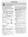
TO SET PARKING
or standard
'
I
safety glasses.
BRAKE
NOTE: Under certain conditions when unit is standing idle
with the engine running, hot engine exhaust gases may
cause "browning" of grass. To eliminate this possibility,
always stop engine when stopping tractor on grass areas.
(See Fig. 8)
Your tractor isequipped with an operator presence sensing
switch
When engine is running, any attempt by the
operator to leave the seat without first setting the parking
brake will shut off the engine
o
Depress clutch/brake pedal into full "BRAKE" position
and hold
I
PUSH IN TO
"DISENGAGE'*
_#_
_.
CAUTION:
Always stop tractor completeiy, asdescribedabove,
beforeleaving the operator's position; to empty
grass catcher, etc.
Place parking brake Iever in "ENGAGED" position and
release pressure from clutch/brake pedal Pedal should
remain in "BRAKE" position1 Make sure parking brake
will hold tractor secure
THROTTLE
I
The operation of any tractor can result in foreign objects thrown into the eyes, which can result
in severe eye damage. Always wear safety glasses or eye shields while operating your tractor
or performing any adjustments or repairs. We recommend a wide vision safety mask over the
HOW TO USE YOUR TR ,CTOR
o
'1'
TO USE CHOKE
CONTROL
(See Fig. 8)
Use choke control whenever you are starting a cold engine
Do not use to start a warm engine
° To engage choke control, pull knob out. Slowly push
knob in to disengage.
ATTACHMENT CLUTCH
SWITCH PULL OUT TO
"ENGAGE",
TO USE THROTTLE
CONTROL
(See Fig, 8)
Always operate engine at full throttle
•
Operating engine at less than ful! throttle reduces the
battery charging rate.
o Full throttle offers the best bagging and mower performance
IGNITION
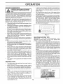
TO MOVE FORWARD
(See Fig. 8)
The direction and speed of movement is controlled by the
motion control lever
MOTION
CONTROL
LEVER
HEIGHT
"DRIVE"
POSITION
ADJUSTMENT
_
KNOB
\
"DISENGAGED"
POSITION
PARKING
BRAKE
"ENGAGED"
POSITION
(See Fig. 8)
MOWER BLADES ',
Move attachment clutch switch to "DISENGAGED"
position
GROUND DRIVE•
Depress ciutchibrake pedal into full "BRAKE" position
,
Move motion control lever to neutral (N) position
IMPORTANT:
THE MOTION CONTROL LEVER DOES
NOT RETURN TO NEUTRAL (N) POSITION WHEN THE
CLUTCH/BRAKE PEDAL tS DEPRESSED
ENGINE •
Move throttle control to stow (,._) position
Never use choke to stop engine
o
Release parking brake and clutch/brake pedal
•
Slowly move motion control lever to desired position.
MOWER
CUTTING
HEIGHT
(See
-
Turn knob clockwise ( f--1 ) to raise cutting height.
°
Turn Knob counterclockwise
height
(_,)to
lower cutting
The cutting height range is approximately 1-1/2" to 4-1/2"
The heights are measured from the ground to the blade tip
with the engine not running These heights are approx,mate and may vary depending upon soil conditions, heigh;
of grass and types of grass being mowed
NOTE: Failure to move throttle control to slow (,e_)
position and allowing engine to idle before stopping may
cause engine to *'backfire"
,
Start tractor with motion control lever in neutral (N)
position.
The cutting height is controlled by turning the height adjustment knob in desired direction.
STOPPING
Turn ignition Key to "OFF" position and remove key
Always remove key when leaving tractor io prevent
unauthorized use
•
TO ADJUST
Fig, 8)
FIG. 8
•
AND BACKWARD
13
•
The average lawn should be cut to approximately 2-1/2
_nches during the cool season and to over 3 inches
during hot months For healthier ancl better looking
lawns, mow often and after moderate growth
•
For best cutting performance, grass over 6 inches _n
height shouid be mowed twice
MaKe the first cut
_elatwely h_gh; tl_e second to desired height
OPERATION
i l!l
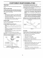
TO ADJUST
nln!,
GAUGE
i
nlll
Ullllil
i
WHEELS
nUll
IIII
I
I'1
(See Fig. 9)
Adjust mower to desired cutting height
Lower' mower with lift control Remove retainer spring
and clevis pin which secure each,gauge wheel bar.
o
Lower gauge wheels to ground Raise gauge wheeis
slightly to align holes in bracket and gauge wheel bar
and insert clevis pin. Gauge wheels should be slightly
off the ground,
o
'
II
I
Adjust gauge wheels with tractor on a flat level surface.
,
I '1
ll,,lul, nlllll
TO OPERATE
I
hills
with stopes
greater
15down
° and
CAUTION:
Do not
drive than
up or
do not drive across any slope.
I
I
o
Choose the slowest speed before starting up or down
hills,
e
Avoid stopping or changing speed on hills,,
If slowing is necessary, move throttle control lever to
slower position,
If stopping is absolutely necessary, push clutch/brake
pedal quickly to brake position and engage parking
brake
o
Replace retainer spring into clevis pin,
ON HILLS
o
o
Move motion control lever to neutral (N) position,
THE
MOTION
CONTROL
LEVER
DOES
NOT RETURN TO NEUTRAL (N) POSITION WHEN THE
CLUTCH/BRAKE PEDAL IS DEPRESSED
"
To restart movement, slowly release parking brake and
clutch/brake pedal
*
Slowly move motion control lever to slowest setting
o Make all turns slowly
IMPORTANT:
TO TRANSPORT
(See Figs. 7 and 11)
When pushing or towing your tractor, be sure to disengage
transmission by placing freewheel control in freewheeling
position. Free wheel control is located at the rear drawbar
of tractor.
FIG. 9
TO OPERATE
MOWER
(See Figs. 7 and 8)
Your tractor is equipped with an operator presence sensing
switch. Any attempt by the operator to leave the seat with
the engine running and the attachment clutch engaged will
shut off the engine
o Select desired height of cuL
°
Lower mower with attachment lift control
•
Start mower blades by engaging attachment clutch
control
,
TO STOP MOWER BLADES - disengage attachment
clutch control
°
Raise attachment
ment lift control,
lift to highest position with attach-
°
Remove retainer spring from freewheel control rod.
o
Push control rod in to disengage transmission and
reinsert retainer spring into control rod hole now on
back side of the bracket.
o
Do not push or tow tractor at more than two (2) MPH
°
To reengage transmission, reverse above procedure.
NOTE: To protect hood from damage when transporting
your tractor on atruck or a trailer, be sure hood isclosed and
secured to tractor. Use an appropriate means of tying hood
to tractor (rope, cord, etc.)_
CAUTION: Do not operate the mower
without either the entire grass catcher,
on mowers so equipped, or the discharge guard in place,
\
-DISCHARGE
GUARD
FIGo 10
14
FIG. 11
TO START
CHECK
ENGINE
OIL
LEVEL
The engine in your tractor has been shipped, from the
factory,, already filled with summer weight oil.,
.
Check engine oil with tractor onlevef ground.
•
Unthread and remove oil fill cap/dipstick; wipe oil off
Reinsert the dipstick into the tube and rest oil fill cap on
the tube Do not thread the cap onto the tube. Remove
and read oil level. If necessary, add oil until "FULL"
mark on dipstick is reached. Do not overfill.
,,
For cold weather operation you should change oil for
easier starting (See "OIL VISCOSITY CHART" in the
Customer Responsibilities section of this manual).
,,
To change engine oil, see the Customer Responsibilities section in this manual.
(See Fig. 8)
When starting the engine for the first time or if the engine
has run out of fuel, it will take extra cranking time to move
fuei from the tank to the engine..
•
Depress clutch/brake pedal and set parking brake
•
Place motion control lever in neutral (N) position.
.
Move attachment clutch to "DISENGAGED" position "
•
Move throttle control to fast (,,_) position
•
Pull choke control out for a cold engine start attempt
Fora warm engine start attempt the choke control may
not be needed..
(See Fig. 12)
o
ENGINE
Note: Before starting, read the warm and cold starting
procedures below
"
Insert key intoig nition and turn key clockwise to"START"
position and release key as soon as engine starts. Do
not run starter continuously for more than fifteen seconds per minute, If the engine does not start after
several attempts, push choke control in, wait a few
minutes and try again. If engine still does net start, pull
the choke control out and retry.
WARM WEATHER STARTING (50 ° F and above)
•
°
/DIPSTICK
L
FIG. 12
ADD
COLD WEATHER STARTING (50 ° F and below)
o When engine starts, slowly push choke control in until
the engine begins to run smoothly Continue to push
the choke control in small steps allowing the engine to
accept small changes in speed and toad, until tne
choke control is fully in, If the engine starts to run
roughly, pull the choke control out slightly for a few
seconds and then continue to push the control in
slowly, This may require an engine warm-up period
from several seconds to several minutes, depending
on the temperature
HYDROSTATIC TRANSMISSION WARM UP
GASOLINE
•
Fill fuel tank. Use fresh, clean, regular unleaded
gasoline with a minimum of 87 octane_ (Use of leaded
gasoline wifl increase carbon and lead oxide deposits
and reduce valve life). Do not mix oil with gasoline,
Purchase fuel in quantities that can be used within 30
days to assure fuel freshness.
IMPORTANT: WHEN OPERATtNG IN TEMPERATURES
BELOW 32°F(0°C), USE FRESH, CLEAN WINTER GRADE
GASOLINE TO HELP INSURE GOOD COLD WEATHER
STARTING
WARNING:
Experience indicates that alcohol blended
fuels (called gasohol or using ethanol or methanol) can
attract moisture which leads to separation and formation of
acids during storage. Acidic gas can damage the fuel
system of an engine while in storage To avoid engine
problems, the fue! system should be emptied before storage of 30 days or longer. Drain the gas tank, start the
engine and let it run until the fuel lines and carburetor are
empty. Use fresh fuel next season See Storage Instructions for additional information
Never use engine or
carburetor cleaner products in the fuel tank or permanent
damage may occur.
ii iiiiiiii
ii
When engine starts, slowly push choke control in until
the engine begins to run smoothly, If the engine starts
to run roughly, pull the choke control out slightly for a
few seconds and then continue to push the control in
slowly
The attachments and ground drive can now be used, If
the engine does not accept the load, restart the engine
and allow it to warm up for one minute using the choke
as described above,,
•
Before driving the unit in cold weather, the transmission should be warmed up as follows:
o Be sure the tractor is on level ground
° Place the motion control lever in neutral
Release the parking brake and let the clutch/brake
slowly return to operating posilion
• Allow one minute for transmission to warm up
This can be done during the engine warm up
period
•
The attachments can be used during the engine warmup period after the transmission has been warmed up
and may require the choke control be pulled out slightly
NOTE: II at a high altitude (above 3000 feet) or in cold
temperatures (below 32 F) the carburetor fuel mixture may
need to be adjusted for best engine performance, See "TO
ADJUST CARBURETOR" in the Service and Adjustments
section of this manual
i
filler neck. Do not overfill Wipe off any
CAUTION:
bottom
of gas
spilled
oil or Fill
fuel.to Do
not store,
spilltank
or
use gasoline near an open flame.
15
OPERATmON
PURGE
TRANSMISSION
•
CAUTION: Never engage or disengage
freewheel lever while the engine is runo
To ensure proper operation and performance, it is recommended that the transmission be purged befor_ operating
tractor for the first time, This procedure wilt remove any
trapped air inside the transmission which may have developed during shipping of your tractor
IMPORTANT: SHOULD YOUR TRANSMISSION REQUIRE
REMOVAL FOR SERVICE OR REPLACEMENT,
fT
SHOULD BE PURGED AFTER REINSTALLATION
BEFORE OPERATING THE TRACTOR,
°
Place tractor safely on level surface with engine off and
parking brake set,
°
Disengage trar_smission by placing freewheel control
in freewheeling position (See "TO TRANSPORT" in
this section of manual)_
,,
Sitting in the tractor seat, start engine. After the engine
is running, move throttle controi to slow (.,_,) position
With motion control lever in neutral (N) position, slowly
disengage clutch!brake pedal,,
•
Move motion control lever' to full forward position and
hold for five (5) seconds. Move lever to full reverse
position and hold for five (5) seconds, Repeat this
procedure three (3) times
NOTE: During this procedure there will be no movement of
drive wheels. The air is being removed from hydraulic drive
system,
,, Move motion control lever to neutral (N) position. Shutoff engine and set parking braker
•
Engage transmission by placing freewheel control in
driving position (See "TO TRANSPORT" in this section
of manual)
= Sitting in the tractor seat, start engine. After the engine
is running, move throttle control to half (1/2) speed
With motion control lever in neutral (N) position, slowly
disengage clutch/brake pedal
=
Slowly move motion control lever forward, after the
tractor moves approximately five (5) feet, slowly move
motion control lever to reverse position. After the
tractor moves approximately five (5) feet return the
motion control lever to the neutral (N) position, Repeat
this procedure with the motion control lever three (3)
times
o Your tractor is now purged and now ready for normal
operation
MOWING
.
•
•
=
',
TIPS
Tire chains cannot be used when the mower housing
is attached to tractor
Mower should be properly leveled for best rnowing
performance. See"TO LEVEL MOWER HOUSING" in
the Service and Adiustments section of this manual
The left r_anU side ol; mower should be used for trim°
rning
Drive so that clippings are discharged onto the area
that has been cut Have the cut area to the right of the
tractor. This witl result in a more even distribution of
clippings and more uniform cutting
When mowing large areas, siart by turning to the nglqt
so that chppings will discharge away from shrubs
fences driveways, etc After one or two rounUs, mow
in the opposite d_rection making left hand turns until
16
finished (See Fig 13)
,,
o
If grass is extremely tall, it should be mowed twice to
reduce load and possible fire hazard from dried clippings Make first cut relatively high; the second to the
desired height,
Do not mow grass when it is wet, Wet grass will plug
mower and leave undesirable clumps. Allow grass to
dry, before mowing
Always operate engine at full throttle when mowing to
assure better mowing performance and proper discharge of material. Regulate ground speed by selecting a low enough gear to give the mower cutting
performance as well as the quality of cut desired
When operating attachments, select a ground speed
that will suit the terrain and give best performance of
the attachment being used.
f
FIG. 13
MULCHING
MOWING
TIPS
iMPORTANT:
FOR BEST PERFORMANCE,
KEEP
MOWER HOUSING FREE OF BUILT-UP GRASS AND
TRASH CLEAN AFTER EACH USE
•
The special mulching blade will recur the grass clippings many times and reduce them in size so that as
they fall onto the lawn they will disperse into the grass
and not be noticed° Also, the mulched grass will
biodegrade quickly to provide nutrients for the lawn.
Always mulch with your highest engine (blade) speed
as this will provide the best recutting action of the
blades.
o Avoid cutting your lawn when it is wet° Wet grass tends
to form clumps and interferes with the mulching action.
The best time to mow your lawn is the early afternoon.
At this time the grass has dried and the newly cut area
will not be exposed to the direct sun°
•
For best results, adjust the mower cutting height so that
the mower cuts off only the top one-third of the grass
blades (See Fig, 14). For extremely heavy mulching,
reduce your width of cut on each pass and mow slowly,.
°
Certain types of grass and grass conditions may re*
quire that an area be mulched a second time to
completely hide the clippings When doing a second
cut, mow across or perpendicular to the first cut path
"
Change your cutting pattern from week to week Mow
north to south one week then change io east to westtl_e
next week This will help prevent matting and graining
of the lawn
MAX 1/3
FIG. 14
CUSTOME
RESPONSIBmL
i.l....m,l,,,u
MAINTENANCE
SCHEDULE
'' '"'"Check
T
.,_f-__._q
u'.
_,
Brake'"O'p"eralior_'
_[_ ' '
Check
Tire Pressure
_
Check
for Loose Fasteners
v"
a
SharPen/Replace
C
Lubrication
Mower
Ba!tery
Level/Recharge
Clean
Battery
and Terminals
R
Check
Transaxfe
Adjust
Blade
Adjust
Motion
Drive Belt(s)
Check
Engine
Oil Level
N
I
Belt(s)
9,
_
'
9,_'
'
9.'
"
9 ,_
c_..:_,g.:_,,##,0""
"" t
_
....
w",
DATES
1"-
.....................
'
!
v'
V's
Tension
Tension
...............
Air Filter
Clean
Air Screen
i
e,"
,,
Oil
Clean
Muffler/Spark
Replace
i
Cooling
Engine
G i Inspect
'
Blades
Check
E
imll
Chart
0
Change
i.ll
"
,,:-
/___,,_ERVICE
SERVICE
i
____o_
AS YOU COMPLETE
REGULAR
ES
Attester
Oil Filter (II equipped)
l,i
Engine
-
Cooling
Fins
Replace
Spark
Replace
Air Filter Paper
Replace
Fuel Filter
1., Change
mo_e
often
when
2 - Service
more
often
when
3 - if equipped
4 - Replace
GENERAL
w}lh oil filter,
blades
more
w"
w'%
Plug
i
e,'
operating
aperaffng
change
often
Cartridge
when
under
a heavy
in dirly
or dusty
oft every
50 ho_rs
mowing
in sandy
load or in high
ambient
temperatures
conditions
5 - If equipped with adjustable system
6, - Not
req_ired
7 - Tighlen
soil
De nol
lront
i{ equipped
axle
pivot
wilh
mainlenance-iree
bo_t to 351I
-Ibs
ovenighlen
RECOMMENDATIONS
LUBRICATION
The warranty on this tractor does not cover items that have
been subjected to operator abuse or negligence,
To
receive full value from the warranty, operator must maintain
tractor as instructed in this manual
(_TtE
(_ SPINDLE
CHART
ROD BALL JOINTS
ZERK --
SPINDLE
Some adjustments will need to be made periodically to
properly maintain your tractor,
(_) STEERING
SECTOR GEAR
TEETH
Once a year you should replace the spark plug, clean
or replace air filter, and check blades and belts for
wear A new spark plug and clean air filter assure
proper air-fuel mixture and help your engine run better
and last longer,
BEFORE
EACH
ZERK (_
WHEEL (_)
BEARING ZERK
BEARING ZERK
All adjustments in the Service and Adjustments section of
this manual should be checked at least once each season
.
battery
maximum
ENGINE (_
USE
•
Cr_eck engine Oil level
•
Check brake operation
°
.
Check tire pressure
Check for loose fasteners
_') SPRAY SILICONE
IMPORTANT:
DO NOT OIL OR GREASE THE PIVOT POINTS
WHICH HAVE SPECIAL NYLON BEARINGS
VISCOUS LUBRt,
CANTS WILL ATTRACT DUST AND DIRT THAT WILL SHORTEH
THE LIFE OF THE SELF-LUBRICATING
BEARINGS,
IF YOU
FEEL THEY MUST BE LUBRICATED
USE ONLY A DRY PaW
DERED GRAPHITE
TYPE LUBRICANT
SPARINGLY
('D GENERAL
LUBRICANT
PURPOSE GREASE
(_ REFER TO CUSTOMER
17
(MOVE BOOTS TO LUBRICATEt
RESPONS1BILITIES
ENGINE*'
SECTION
,i,,,lllll_ll
n
i i
iinl
nlulun
CUSTO
,,,,,,n,,nn i
H
ii u
RESPONSmBILITUES
,,
n, mnn ,u i,,,,l,
,
TRACTOR
TO SHARPEN
Always observe safety rules when performing any maintenance,.
Care should be taken to keep the blade balanced, An
unbalanced blade wifl cause excessive vibration and eventual damage to mower and engine,
BRAKE
OPERATION
°
ff tractor requires more than six (6) feet stopping distance
at high speed in highest gear, then brake must be adjusted
(See "TO ADJUST BRAKE" in the Service and Adjustments section of this manual).
°
TIRES
-
BLADE
(See Fig. 16)
The blade can be sharpened with a file or on a grinding
wheel. Do not attempt to sharpen while on the mower,.
To check blade balance, you will need a 5/8" diameter
steel bolt, pin, or a cone balancer, (When using a cone
balancer, fotlow the instructions supplied with balancer).
•
Maintain proper air pressure in all tires (See "PRODUCT SPECIFICATIONS" on page 3 of this manual)
"
Keep tires free of gasoline, oil, or insect control chemicals which can harm rubber.
Slide blade on to an unthreaded portion of the steel bolt
or pin and hold the bolt or pin parallel with the ground.
tf blade is balanced, it should remain in a hodzonta!
position If either end of the blade moves downward,
sharpen the heavy end until the blade is balanced
,'
Avoid stumps, stones, deep ruts, sharp objects and
other hazards that may cause tire damage
NOTE: Do not use a nail for balancing blade.. The lobes of
the center hole may appear to be centered, but are noL
CENTER HOLE
BLADE
CARE
For best results mower blades must be kept sharp,
ptace bent or damaged blades.
BLADE
REMOVAL
\
Re-
(See Fig. 15)
•
Raise mower to highest position to allow access to
btades.
.
Removehexbot,
blade.
.
install new or resharpened blade with trailing edge up
towards deck as shown.
•
Reassemble hex bolt, lock washer and flat washer in
exact order as shown
5/8" BOLT
tBLAOE
OR PIN '_
/
/
fock washer and fiat washer secudng
FIG, 16
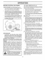
BATTERY
•
Tighten bolt securely (30-35 Ft. Lbs torque).
IMPORTANT: BLADE BOLT IS GRADE 8 HEATTREATED
Your tractor has a battery charging system which is sufficient for normal use However, periodic charging of the
battery with an automotive charger will extend its life
NOTE: We do not recommend sharpening blade - but if you
do, be sure the blade is balanced,.
.
Keep battery and terminals clean
•
Keep battery boIts tight
•
Keep smal vent hoies open
"
Recharge at 6-10 amperes for 1 hour.
MANDREL
BLA?
_/
TO CLEAN BATTERY AND TERMINALS
ASSEMBLY
Corrosion and dirt on the battery and terminals can cause
the battery to "leak" power
_'J'_
FLAT WASHER_
"_.
:
_,_L_"_...._
EDGE UP
/
HEX
BOLT G=ADE°,' .
'A GRADE 8 HEAT TREATED BOLT CAN BE
IDENTIFIED BY SIX LINES ON THE BOLT HEAD,
FIG. 15
18
-
Remove terminal guard
.
Disconnect BLACK battery cable first then RED
battery cable and remove battery from tractor
,,
Rinse the battery with plain water and dry
o
Clean terminals and balery cable ends with w_rebrusrl
until bright
•
',
Coat terminals w_th grease or petroleum telly
Reinstall battery {See "CONNECT BATTERY" in the
Assembly section of this manual)
CUSTOMER
=
= =
m,,iHH, m=,.
TRANSAXLE
RESPONS
,,11.111
COOLING
,,,.1,,1, m
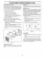
TO CHANGE ENGINE OIL (See Figs 17 and 18)
Determine temperature range expected before oil change
All oi! must meet API service classification SF, SG, or SH
Be sure tractor is on level sudace
The fan and cooling fins of transmission should be kept
clean to assure proper cooling
Do not attempt to clean fan or transmission while engine is
running or while the transmission is hoL To prevent
possible damage to seals, no not us_ high pressure water
or steam to clean transaxle.
•
Inspect cooling fan to be sure fan blades are intact and
clean.
•
inspect cooling fins for dirt, grass clippings and other
materials, To prevent damage to seals, do not use
compressed air or high pressure sprayer.
TRANSAXLE
LITIES
=
PUMP FLUID
The transaxte was seated at the factory and fluid maintenance is not required for the life of the transaxfe Should
the transax[e ever leak or require servicing, contact your
nearest authorized service center/departmento
.
•
Oil will drain more freely when warm..
Catch oil in a suitable container
o
Remove oil fill cap/dipstick Be careful not to allow dirt
to enter the engine when changing oil.
o
Remove drain plug.
=
After oil has drained completely, replace oil drain plug
and tighten securely.
°
Refill engine with oi] through oil fill dipstick tube, Pour
slowly. Do not overfill. For approximate capacity see
"PRODUCT SPECIFICATIONS"
on page 3 of this
manual
Use gauge on oil fill cap/dipstick for checking level,,
Insert dipstick into the tube and rest the oil fill cap on the
tube. Do not thread the cap onto the tube when taking
reading
Keep oil at "FULL" line on dipstick Tighten
cap onto the tube securely when finished,
V-BELTS
Check V-betts for deterioration and wear after 100 hours of
operation and replace if necessary The belts are no[
adjustable, Replace belts if they begin to slip from wear,
OIL
ENGINE
_'
DRAIN
PLUG
LUBRICATION
Only use high quality detergent oil rated with API service
classification SF, SG, or SH. Select the oil's SAE viscosity
grade according to your expected operating temperature
SAE VISCOSITY GRADES
AIR
SCREEN
°F'
°C
:_o,'
-30:"
or
-20'
TEMPERATURE
50° _o 40°
.10 °
0_
RANGE ANTICIPATED
80°
tO_
88°
20'
FIG. 18
tso
o
......
FILL
CAP/DIPSTICK
48, '_
BEFORE NEXT OIL CHANGE
CLEAN
FIG. 17
AIR SCREEN
(See Fig. 18)
Air screen must be kept free of dirt and chaff to prevent
engine damage from overheating. Clean with a wire brush
or compressed air to remove dirt and stubborn dried gum
fibers,
Change the oil after the first two hours of operation and
every 50 hours thereafter or at least once a year if the
tractor is not used for 59 hours in one year
CLEAN
Check the crankcase oil level before starting the engine
and after each eight (8) hours of operation, Tighteq oil fill
cap!dipstick securely each time you check the oil level
AIR INTAKE/COOLING
AREAS
To insure proper cooling, make sure the grass screen,
cooling fins, and other external surfaces of the engine are
kept clean at all times
Every 1O0 hours of operation (more often under extremely
dusty, dirty conditions), remove the blower housing and
other cooling shrouds, Clean the cooling fins and external
surfaces as necessary Make sure the cooling shrouds are
reinstalte_
NOTE: Operating the engine willl a blocked grass screen
dirty or plugged cooling fins. and/or cooling shrouds removed will cause engine damage due lo overheating
!9
CUSTOMER
AIR FILTER
RESPO
;IBILITNES
MUFFLER
(See Fig. 19)
Your engine will not run property using a dirty air' filter
Clean the foam pre-cleaner after every 25 hours of operation or every season_ Service paper cartridge every 100
hours of operation or every season, whichever occurs first
Inspect and replace corroded muffler and spark attester (if
equipped) as it could create a fire hazard and/or damage.
Service air cleaner more often under dusty conditions
Replace spark plugs at the beginning of each mowing
season or after every 100 hours of operation, whichever
occurs first. Spark plug type and gap setting are shown in
"PRODUCT SPECIFICATIONS" on page 3 of this manual.
.
SPARK
Loosen knob and remove cover
TO SERVICE PRE-CLEANER
.
Slide foam pre-cleaner off cartridge.
.
Wash it in liquid detergent and water,
•
Squeeze it dry in a clean cloth,. Allow it to dry.
IN-LINE
Saturate it in engine oil_ Wrap it in clean, absorbent
cloth and squeeze to remove excess oil
TO SERVICE CARTRIDGE
Replace a dirty, bent, or damaged cartridge,
NOTE: Do not wash the paper cartridge or use pressurized
air, as this wilt damage the cartridge.
.
Remove nut and cartridge plate.
.
Reinstall the pre-cteaner (cleaned and oiled) over the
paper cartridge
o
Check rubber' seal for damage and proper position
around stud. Replace if necessary.
•
Reassemble air cleaner, cartridge plate, and nut.
•
Reinstall air cleaner cover and secure by tightening
knob.
CARTRIDGE
FOAM
_
P EC'EA.E.
FUEL FILTER
(See Fig, 20)
The fuel filter should be replaced once each season° tf fuel
filter becomes clogged, obstructing fuel flow to carburetor,
replacement is required,
=
°
PLUGS
,,
With engine coot, remove filter and plug fuel line
sections
°
Place new fuel filter in position in fuel line with arrow
pointing towards carburetor.
Be sure there are no fuel line leaks and clamps are
properly positioned
.
-
Immediately wipe up any spilled gasoline..
_'_
CLAMP
,h
CLAMP
' FUEL FILTER
FIG. 20
CLEANING
RUBBER
SEAL
=
Clean engine, battery, seat, finish, etc. of all foreign
matter.
•
Keep finished surfaces and wheels free of all gasoline,
oil, etc.
o
Protect painted surfaces with automotive type wax.
We do not recommend using a garden hose to clean your
tractor unless the electrical system, muffler', air filter and
carburetor are covered to keep water ouL Water in engine
can result in a shortened engine life
FIG.
ENGINE
19
OIL FILTER
Replace the engine oil filter every season or every other oil
change if the tractor is used more than 100 hours in one
year
2O
.................
i,i1,1 ii,
i
LIIIIp
.................................................
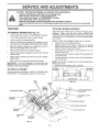
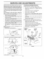
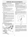
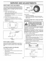
SERVUCE AND ADJUSTMENTS
ii
....
i1,111,,,111, , i
,,11,
CAUTION: BEFORE PERFORMING ANY SERVICE OR ADJUSTMENTS:
o
Depress clutch/brake
pedal fully and set parking brake.
Place attachment clutch in "DISENGAGED" position.
Place
motion key
control
lever
neutral key.
(N) position.
Turn ignition
"OFF"
andin remove
Make sure the blades and all moving parts have completely stopped.
Disconnect spark plug wire from spark plug and place wire where it cannot come in contact with
plug.
,,,,,_....
...............................................
o
_
@
o
o
TRACTOR
TO LEVEL MOWER
TO REMOVE
MOWER
Adjust the mower while tractor is parked on level ground or
driveway.
Make sure tires are properly inflated (See
"PRODUCT SPECIFICATIONS" on page 3 of this manual).
If tires are over or underinflated, you will not properly adjust
your mower
(See Fig. 2'!)
.
Place attachment clutch in "DISENGAGED"
o
Turn height adjustment knob to iowest setting,
°
Lower mower to its lowest position
=
Remove retainer spring holding antkswaybar to chassis bracket and disengage anti-swaybar from bracket,r
•
Remove retainer spdngs from suspension
deck and disengage arms from deck,
°
Raise attachment lift to its highest position.
•
-
Remove two retainer springs from each front link and
remove links
,
o
Slide mower forward and remove belt from electric
clutch pulley,
°
position
SIDE-TO-SIDE ADJUSTMENT (See Figs 21 and 22)
,
Raise mower to its highest position
°
Measure height from bottom of deck curl to ground
level at front corners of mower Distance "A" on both
sides of mower should be the same
arms at
= Slide mower out from under right side of tractor,
IMPORTANT: IF AN ATTACHMENT OTHER THAN THE
MOWER DECK tS TO BE MOUNTED ON THE TRACTOR,
REMOVE THE FRONT LINKS
TO INSTALL
If adjustment is necessary, make adjustment on one
side of mower only
To raise one side of mower, tighten lift link adjustment
nut on that side,
To lower one side of mower, loosen lift link adjustment
nut on that side
NOTE: Each half turn of adjustment nut will change mower
height about 3/16",
Recheck measurements after adjusting,,
E
MOWER
Follow procedure described in "INSTALL MOWER AND
DRIVE BELT" in the Assembly section of this manual
"*
LIFT
LINKS
SUSPENSION
ARMS
HOUSING
ADJUSTMENT
NUT
L. ..V
7
BoTToM
!
:
I
!
GROUNDUNE
,,Y I
I
FIGo 22
FRONT
LINKS
FRONT
MOWER
BRACKET
FRONT SUSPENSION
BRACKETS
ELECTRIC
PULLEY
CHASSIS
BRACKET
RETAINER
SPRINGS
FRONT MOWER
RETAINER
SPRING
ANTI-SWAY
BAR
BRACKET
ADJUSTMENT
RETAINER
SPRINGS
FIGo 21
21
CLUTCH
NUT
SERVICE
ii
AND ADJUSTMENTS
i
,
TO REPLACE
FRONT-TO-BACK ADJUSTMENT (See Figs 23 and 24) IMPORTANT: DECK MUST BE LEVEL SIDE.TO-SIDE IF
THE FOLLOWING FRONT-TO-BACK ADJUSTMENT IS
NECESSARY, BE SURE TO ADJUST BOTH FRONT LINKS
EQUALLY SO MOWER WILL STAY LEVEL SIDE-TO-SIDE
.
•
o
Park tractor on a level surface,, Engage parking brake,
Remove four screws from L H, mandrel cover and
remove cover
o
Roll belt over the top of L.H mandrel puiley
•
Remove belt from electric clutch pulley,
o
Remove belt from idler pulleys
,
Remove any dirt or grass clippings which may have
accumulated around mandrels and entire upper deck
surface,
°
Check primary idter arm and two idlers to see that they
rotate freely,
•
Be sure spring is securely hooked to primary idler arm
and bolt in mower housing,
o
Install new belt onto electric clutch pulley.
o
Roll belt into upper groove of L.H. mandrel pulley.
o
Carefully check belt routing making sure belt is in the
grooves correctly and inside belt keepers.
Reassemble L H mandrel cover.
o
REMOVE L.H,
MANDREL
COVER
SCREWS
MANDREL
T"F"
F"_
BELT
MOWER DRIVE BELT INSTALLATION (See Fig, 25) o Install belt in both idlers. Make sure belt is in both belt
keepers at the idlers as shown.
NOTE: Each full turn of nut "G" will change dim, "F" by
approximately 3/8",
°
Recheck side-to-side adjustmenL
.
DRIVE
MOWER DRIVE BELT REMOVAL (See Fig 25) -
To obtain the _est cutting results, the mower housing
should be adjusted so the front isapprcTximately 1/8" to 1/2"
lower than the rear when the mower is in its highest
position
Check adjustment on right side of tractor.. Measure distance "F" directly in front of and behind the mandrel at
bottom edge of mower housing as shown.
•
Before making any necessary adjustments, check that
both front links are equal in length
•
If links are not equal in length, adjust one link to same
length as other link.
•
To lower front of mower housing, loosen nut"G" on both
front links an equal number of turns.
o When distance "F" is 1/8" to 1/2" lower at front than
rear, tighten nut"H" against trunnion on both front links.
* To raise front of mower housing, loosen nut "H" from
trunnion on both front links. Tighten nut "G" on both
front links an equal number of turns
o When distance "F" is 1/8" to 1/2" lower at front than
rear, tighten nut "H" against trunnion on both front
links,
"_it
MOWER
,
ELECTRIC
CLUTCH
PULLEY
IDLER
PULLEYS
,,.....
FIG, 23
BOTH FRONT LINKS SHOULD BE EQUAL IN LENGTH
SPRING
MANDREL
MOWER
DRIVE BELT
BELT
KEEPER
FIG. 25
NUT"H'
FRONT LINKS
FIG_ 24
22
II,,U,
i
I'
IIII
I1"111'
'
SERVmCE AND ADJUSTMENTS
,uH lU,iH,ilU,,lUllll,'"'NU' U' I '
TO REPLACE
MOWER
BLADE
DRIVE
BELT
.
O
O
Remove mower drive belt (See''TO REPLACE MOWER
DRIVE BELT" in this section of this manual)
Remove mower (See "TO REMOVE MOWER" in this
section of this manual)
Remove four screws from RH mandrel cover and
remove cover. Unhook spring from bolt on mower
housing
o
CarefuNy roll belt off RH. mandrel pulley.
o
Remove belt from center mandrel pulley, idler pulley,
and L.H. mandrel pulley.
I
Make sure attachment clutch and ignition switches are
in "OFF" position..
*
Adjust the three nylon tocknuts until space between
clutch plate and rotor measures 012" at all three slot
locations cut in side of brake plate
(See Fig. 26)
Park the tractor on level surface_ Engage parking brake
I U
-
NOTE: After installing a new electric clutch, run tractor at
full throttle and engage and disengage electric clutch 10
cycles to wear in clutch plate.
ROTOR\
CLUTCH
SLOT (3)_
PLATE
--
012"
Remove any dirt or grass which may have accumulated around mandrels and entire upper deck surface
o
Check secondary idler arm and idler to see that they
rotate freely+
o
Be sure spring is hooked in secondary idler arm and
sway-bar bracket..
ii
Install new belt in lower groove of L H+mandrel pulley,
idler pulley, and center mandrel pulley as shown.
NYLON LOCKNUT (3)
Reconnect spring to bolt in mower housing and reinstall RH mandrel cover..
+
Reinstall mower to tractor (See "INSTALL MOWER
AND DRIVE BELT" in the Assembly section of this
manual)
PLATE
FIG. 27
TO ADJUST
BRAKE
(See
Fig. 28)
Your tractor is equipped with an adjustable brake system
which is mounted on the side of the transaxleo
Roll belt over RHo mandrel pulley. Make sure belt is in
all grooves properly.
o
BRAKE
If tractor requires more than six (6) feet stopping distance
at high speed in highest gear, then brake must be adjusted
o
Depress clutch/brake pedal and engage parking brake.
*
Measure distance between brake operating arm and
nut "A" on brake rod.
Reassemble mower drive belt (See "TO REPLACE
MOWER DRIVE BELT" in this section of this manual)
If distance is other than 1-1/2", loosen jam nut and turn
nut "A" until distance becomes 1-1/2" Retighten jam
nut against nut "A".
LH,
MANDREL
Road test tractor for proper stopping distance as stated
above. Readjust if necessary, If stopping distance is
still greater than six (6) feet in highest gear, further
maintenance is necessary Contact your nearest authorized service center/department
MOWER
BLADE
DRIVE BELT
CENTER
MANDREL
IDLER
PULLEY
WITH PARKING BRAKE "ENGAGED"
NUT "A"
JAM NUT
SECC
IDLER ARM
SPRING
+_.,..._
ARM
FIG, 26
TO ADJUST ATTACHMENT
(See Fig, 27)
OPERATING
CLUTCH
+L
t
The electnc ciutch should provide years of service The
clutch has a buill-in brake that stops the pulley within 5
seconds
Eventually, tile internal Drake will wear whicr,
may cause the mower blades to not engage, or. to not stop
as required Adjustments should be made by your nearest
authonzeo service centerldepartment
FIG. 28
23
u,,u
,i ,w,uuq
un lu u l ,
SERVICE AND ADJUSTMENTS
TO REPLACE
(See Fig. 29)
MOTION
DRIVE BELT
TO ADJUST MOTION
(See Fig. 30)
Park the tractor on level surface Engage parking brake
For ease of service there is a belt installation guide decal on
bottom of left footrest°
tf for any reason the motion control lever wilj not hotd its
position while at a selected speed, it may be adjusted at'_he
friction pack located on the right side of chassis.
Remove mower (See "TO REMOVE MOWER" in this
section of this manual )
BELT REMOVALEngage parking brake (creates slack in belt)..
.
Remove belt from clutching and fan idler pulley&
=
Loosen belt keeper above transaxle pulley.
o
Remove belt from transaxle pulley..
•
Remove belt from engine pulley and front V-idler pulley.
LEVER
The motion control lever has been preset at the factory and
adjustment should not be necessary.
',
•
CONTROL
•
Park tractor' on level surface.. Stop tractor by turning
ignition key to "OFF" position and engage parking
brake
o
Place motion control lever in neutral (N) position
o
While holding Iocknut, loosen jam nut
o
Tighten tocknut 1/4 turn. ,
.
While holding Iocknut, tighten jam nut securely°
.
Pu]t belt out of a!l belt keepers and remove from tractor
BELT INSTALLATION -
NOTE: If for any reason the effort to move the motion
controf lever becomes too excessive, reverse the above
adjustment procedure by loosening tocknut 1/4 turn.
o
Place V part of belt into grooves on engine pulley and
front V-idter, making sure to route belt inside of all belt
keepers.
Road test tractor after adjustment and repeat procedure if
necessary.
•
Route belt on right side, coming from V-idler, towards
back of tractor, above midspan beft keeper and to top
of transaxte pulley.
°
Route belt on left side, coming from engine pulley,
towards back of tractor and through loop in midspan
belt keeper.
°
Place V part of belt into grooves on transaxle and fan
idler pulleys, making sure to route belt inside of all belt
keepers
o
Retighten belt keeper above transaxte pulley
,'
Place belt around clutching idlers as shown, making
sure to route belt inside of all belt keepers.
,,
Check to be sure belt is positioned correctly and is on
proper side of all belt keeper&
Reinstall mower
°
IMPORTANT:
LOCKNUT
JAM NUT
/
/
!
CHECK BRAKE ADJUSTMENT
TRACTOR V-BELT DRIVE SCHEMATIC
VIEWED FROM LHo SIDE OF TRACTOR
CLUTCHING
ENGINE
PULLEY
CLUTCHING
{DLER X
\
TRANSAXLE
BELT
PER
TRANSMISSION
Should your transmission require removal for service or
replacement, it should be purged after reinstallation before
operating the tractor See "PURGE TRANSMISSION" in
Operation section of this manual
ABOVE I
V-IDLER
KEEPER
BELT
'[EEPER
TO ADJUST
I
V-IDLER
AS VIEWED
FROM
!
STEERING
WHEEL
ALIGNMENT
If steering wheel crossbars are not horizontal (left to right)
when wheels are positioned straight forward, remove steering wheet and reassembfe per instructions in the Assembty
section of this manual
BELT
TWISTS
PULLEY
REMOVAL/REPLACEMENT
BELT
KEEPER
FAN
IDLER
BOTTOM
FIG° 29
24
ii,r,l,,,,,,,,,n,,
SERVnCE AND ADJUSTMENTS
FRONT
WHEEL
TOE-IN
ADJUSTMENT
WASI
Front wheel _oe-in is required for proper steering operation
Toe-in was sefat the factory and adjustment should not be
necessary, t! parts in the front axle or steering mechanism
have been rep{aced or damaged, check toe-in and adjust
if necessary,
,-
RETAINING
RING
AXLE
COVER
TO CHECK TOE-IN (See Fig 31) °
Position front wheels straight ahea&
.
Measure distance between wheels at front and rear of
tires (dimensions "A" and "B"),
°
Front dimension "A" should be 1/8" to 1/4" less than
rear dimension "B".,
FIG. 33
REAR WHEEL .
.
"
TO ADJUST TOE-IN (See Figs, 31 and 32) ° Loosen jam nuts at adjustment sfeeves on tie rod,
ii
o
Adjust tie rod until dimension "A" is 1/8" to 1/4" tess than
dimension "B".,
Block rear axle securely,
Remove five (5) hub bolts to allow wheel removal.
Repair tire and reassemble Replace and tighten hub
bolts securely,
TO START ENGINE WITH A WEAK
'See Fig. 34)
Tighten jam nuts securely.
BATTERY
CAUTION: Lead.acid batteries generate explosive gases. Keep sparks, flame
and smoking materials away from batteries.
Always wear eye protection
when around batteries°
your battery is too weak to start the engine, it should be
recharged,
tf "jumper cables" are used for emergency
starting, follow this procedure:
FIG. 3!
i_
IMPORTANT:
YOUR TRACTOR IS EQUIPPEDWlTH
A 12
VOLT NEGATIVE
GROUNDED
SYSTEM
THE OTHER
VEHICLE
MUST ALSO
BE A 12 VOLT
NEGATIVE
GROUNDED
SYSTEM.
DO NOT USE YOUR TRACTOR
BATTERY TO START OTHER VEHICLES
ADJUSTMENT
,
SLEEVES
TO ATTACH JUMPER CABLES •
.
TIE ROD
.... "
•
FIG. 32
Connect each end of the RED cable to the POSITIVE
(+) terminal of each battery, taking care not to short
against chassis
Connect one end of the BLACK cable to the NEGATIVE (-) terminal of fully charged battery,
Connect the other end of the BLACK cable to good
CHASSIS GROUND, away from fuel tank and battery
TO REMOVE CABLES, REVERSE ORDER -
FRONT WHEEL
o
CAMBER
The front wheel camber is not adjustable on your tractor If
damage has occurred to affect the front wheel camber,
contact your nearest authorized service center/department
TO REMOVE
WHEEL
BLACK cable first from chassis and then from the fully
charged battery
RED cable last from both batteries.
FOR REPAIRS
FRONT WHEEL (See Fig 33) °
Block up axle securely
•
•
•
Remove axle cover, retaining ring and washersto atlow
wheei removat
Repair tire and reassemble
Replace washers and snap retmning nng securely _n
axle groove
Replace axle cover
25
FIG. 34
SERVmCE AND ADJUSTMENTS
TO REPLACE
HEADLIGHT
BULB
•
4
o
Raise hood,
•
Pult bulb holder out of the hole in the backside of the
grill
.
"HEADLIGHT
J
INTERLOCKS
'.
HOOD _
Replace bulb in holder and push bulb holder securely
back into the hole in the backside of the grill.
Close hood
•
"4
WIRE
' "`
CONNECTOR
AND RELAYS
Loose or damaged wiring may cause your tractor to run
poorly, stop running, or prevent it from starting
•
Check wiring. See electrical wiring diagram in the
Repair Parts section of this manual
TO REPLACE
FIG. 36
FUSE
ENGINE
TO ADJUST
THROTTLE
(See Fig, 37)
Rep{ace with 30 amp automotive-type plug-in fuse,, The
fuse holder is located behind the dash°
TO ADJUST ATTACHMENT
(See Fig. 35)
LIFT SPRING
•
While holding spring bushing with wrench, loosen jam
nut,
.
Turn adjustment
bolt clockwise to extend
reduce lift effort for heavier attachments,
,,
Turn adjustment
tachments.
°
Retighten
bolt counterclockwise
jam nut against
spring
spring
at-
bushing,
IDLE FUEL
ADJUSTING
NEEDLE
IMPORTANT:
DO NOT ADJUST FOR MAXIMUM SPRING
TENSION
WHEN USING LtGHT ATTACHMENTS
SUCH
ASAMOWER
ADJUST LiFT LEVER SPRING TO AID iN
LIFTING ATTACHMENT,
DO NOTOVERPOWER
SPRING.
WHEN REMOVING
ATTACHMENT,
ALWAYS
ADJUST
SPRING TENSION TO ITS LOWEST POSITION
ADJUSTMENT
CABLE
The throttle control has been preset at the factory and
adjustment should not be necessary. Check adjustment as
described below before loosening cable If adjustment is
necessary, proceed as follows:
o
With engine not running, move throttle conhol lever to
fast ('_) position
u
Check that speed control lever is against stop screw. If
it is not, loosen casing clamp screw and pull throttle
cable until lever is against screw. Tighten clamp screw
securely.
and
for lighter
CONTROL
IDLE SPEED
SCREW
SPRING BUSHING
THROTTLE
CONTROL
CABLE
0
JAM NUT
ATTACHMENT
LIFT SPRING
FIG. 35
TO REMOVE
HOOD
AND
GRILL
ASSEMBLY
(See Fig, 36)
Raise hood,
,,
"
Unsnap headlight wwe connector
Stand m front of tractor Grasp hood at sides, tiIt toward
engine and lift off of tractor.
°
To replace, reverse above procedures
26
TO ADJUST CHOKE CONTROL
(See Figs. 37 and 38)
TO ADJUST
The choke control has been preset at the factory and
adjustment should not be necessary° check adjustment as
described below before loosening cable, If adjustment is
necessary, proceed as follows:
.
With engine not running, move choke control (located
on clash panel) to full choke (N) position,
o Remove air cleaner cover, filter and cartridge plate to
expose carburetor choke (See "AfR FILTER" in the
Customer Responsibilities section of this manual),,
•
Choke should be closed. If it is not, loosen casing
clamp screw and move choke cable until choke is
completely closed, Tighten casing clamp screw securelyr
',
Reassemble air cleaner.
CLOSED
FULL
CARBURETOR
(See
Fig, 37)
The carburetor has been present at the factory and adjustment should not be necessary_ However, minor adjustment
may be required to compensate for differences in fuel
temperature, altitude or Ioad_ If the carburetor does need
adjustment, proceed as follows:
In general, turning the adjusting needles in (clockwise)
decreases the supply of fuel to the engine giving a {eaner
fue!!air mixture Turning the adjusting need{es out (counterclockwise) increases the supply of fuel to the engine
giving a richer fuel/air mixture.
IMPORTANT:
DAMAGE TO THE NEEDLES AND THE
SEATS tN CARBURETOR MAY RESULT IF SCREW IS
TURNED tN TOO TIGHT
PRELIMINARY SETTING -
Be sure you have a clean air filter, and the throttle
control cable is adjusted properly (see "TO ADJUST
THROTTLE CONTROL CABLE in the Service and
Adjustments section of this manual)
.
With engine off turn idle fuel adjusting needle in (clockwise) closing itfinger tight and then turn out (counterclockwise) ! turn
FINAL SETTING o Start engine and allow to warm for five minutes Make
final adjustments with engine running and shift/motion
control lever in neutral (N) position
"
The high idle is set at the factory and cannot be
adjusted.
= Idte speed setting - With throttle control lever in slow
(.,_)
position, engine should idle at 1200 RPM, If
engine idles too slow or fast, turn idle speed adjusting
screw in or out unti_ correct idle is attained.
•
Idle fuel needle setting - With throttle control lever in
slow (._,) position, turn idie fuel adjusting needle in
(clockwise) L,ntil engine speed decreases and then
turn out (counterclockwise) approximately 3/4 turn to
obtain the best low speed performance
o Recheck idle speed. Readjust if necessary,
ACCELERATION TEST •
Move throttle control lever from slow (_)
to fast (,_)
position, If engine hesitates or dies, turn idle fuel
adjusting needle out (counterclockwise) 1/8 turn, Repeat test and continue to adjust, if necessary, until
engine accelerates smoothly
High speed stop is factory adjusted, Do not adjust-damage
may result
IMPORTANT:
NEVER TAMPER WITH THE ENGINE
GOVERNOR, WHICH tS FACTORY SET FOR PROPER
ENGINE SPEED OVERSPEEDING THE ENGINE ABOVE
THE FACTORY HiGH SPEED SETTING CAN BE
DANGEROUS IF YOU THINK THE ENGINE-GOVERNED
HIGH SPEED NEEDS ADJUSTING, CONTACT YOUR
NEAREST
AUTHORIZED
SERVICE
CENTER/
DEPARTMENT, WHICH HAS PROPER EQUIPMENT AND
EXPERIENCE
TO
MAKE
ANY
NECESSARY
FOR
FIG. 38
ADJUSTMENTS
27
n
STORAGE
ENGINE
Immediately prepare your tractor for storage at the end of
the season or if the tractor will not be used for 30 days or
more,
FUEL SYSTEM
IMPORTANT:
tT IS IMPORTANT TO PREVENT GUM
DEPOSITS FROM FORMING IN ESSENTIAL
FUEL
SYSTEM PARTS SUCH AS CARBURETOR, FUEL FILTER,
FUEL HOSE, OR TANK DURING STORAGE.
ALSO,
EXPERIENCE INDICATES THAT ALCOHOL BLENDED
FUELS (CALLED GASQHOL OR USING ETHANOL OR
METHANOL) CAN ATTRACT MOISTURE WHICH LEADS
TO SEPARATION AND FORMATION OF ACIDS DURING
STORAGE.
ACIDIC GAS CAN DAMAGE THE FUEL
SYSTEM OF AN ENGINE WHILE IN STORAGE
CAUTION: Never store the tractor with
gasoline in the tank inside a building
where fumes may reach an open flame
or spark,
Allow the engine to cool
before storing in any enclosure,
TRACTOR
Remove mower from tractor for winter storage. When
mower is to be stored for a period of time, clean it thoroughly, remove aH dirt, grease, leaves, etc. Store in a
clean, dry area..
°
Clean entire tractor (See "CLEAN ING" in the Customer
Responsibilities section of this manual)
o
Inspect and replace belts, if necessary.(See belt replacement instructions in the Service and Adjustments
section of this manual).
•
Lubricate as shown in the Customer Responsibilities
section of this manual
°
Be sure that all nuts, bolts and screws are securely
fastened Inspect moving parts for damage, breakage
and wear. Replace if necessary.
"
Touch up all rusted or chipped paint surfaces; sand
lightly before painting.
Fully charge the battery for storage.
o
After a period of time in storage, battery may require
recharging
°
To help prevent corrosion and power leakage during
long periods of storage, battery cables should,, be
disconnected andbatterycleanedthoroughly(see
TO
CLEAN BATTERY AND TERMINALS" in the Customer Responsibilities section of this manual).
•
Drain the fuel tank.
o
Start the engine and let it run until the fuel lines and
carburetor are empty
o
Never use engine or carburetor cleaner products in the
fuel tank or permanent damage may occur
Use fresh fue! nex_ season.
°
NOTE: Fuel stabilizer is an acceptable alternative in
minimizing the formation of fuel gum deposits during storage. Add stabilizer to gasoline in fuel tank or' storage
container. Always follow the mix ratio found on stabilizer
container. Run engine at least 10 minutes after adding
stabilizer to allow the stabilizer'to reach the carburetor. Do
not drain the gas tank and carburetor if using fuel stabilizer
ENGINE
OIL
Drain oil (with engine warm) and replace with clean engine
oil. (See "ENGINE" in the Customer Responsibilities
section of this manual)..
BATTERY
•
o
CYLINDERS
After cleaning, leave cables disconnected and place
cables where they cannot come in contact with battery
terminals.
°
Remove spark plug(s)
o
Pour one ounce of oil through spark plug hole(s) into
cylinder(s)
o
Turn ignition key to"START" position for a few seconds
to distribute oil
,
Replace with new spat'k plug(s)
OTHER
o
Be sure battery drain tube is securely attached
o
Do not store gasoline from one season to another'.
.
If battery is removed from tractor for storage, do not
store battery directly on concrete or damp surface&
o
Replace your gasoline can if your can starts to rust
Rust and/or dirt in your gasoline will cause problems
•
tf possible, store your tractor indoors and cover it to
give protection from dust and dirt..
°
Cover your tractor with a suitable protective cover that
does not retain moisture Do not use plastic. Plastic
cannot breathe which allows condensation to form and
will cause your tractor to rust.
IMPORTANT: NEVER COVER TRACTOR WHILE ENGINE
AND EXHAUST AREAS ARE STILL WARM
28
ilu iiil,l,ul i,, iii ii,
i, ii
TBOUBLESHOOTmNG
,,H, UH,I
PROBLEM
Wilt not start
CAUSE
to start
t
Out of fuel
Engine not "CHOKED"
Engine flooded
Bad spark p_ug
Dirty air filter
Dirty fuel filter
Water in fuel
8
9
Loose or damaged wiring
Carburetor out of adjustment
1
2
3
4
5
6
7
properly
Engine valves out of adjustmenl
Dirty air filter
Bad spark plug
Weak or dead battery
Dirty tue_ tilter
Stale or dirty fuel
Loose or damaged wiring
Carburetor out of adjuslment
H''"m,U,'H'H',H,"
I ' I
I
I
1
Fill lue! Iank
2
3
4
5
6
7
See "TO START ENGINE" in Operation section
Wait several minutes belore attempting to start
Replace spark plug
Clean/replace air fiiter
Replace fuel tilter
Drain fuel tank and carburetor, refill tank with fresh
8
9
gasoline and replace fuel fiIter
Check nit wiring
See _To Adiust Carburetor" in Service Adjustments
section
.......................... '"HmH
U'
I'
Contact an authorized
service center/department
I
2
3
4
5
6
7
Clean/replace air filter
Reptace spark p!ug
Recharge or replace battery
Replace fuel filter
Drain fuel tank and refill with flesh gasoline
Check all wiring
See "To Adiusl Carburetor" in Set€ice Adjustments
section
8
Contact an authorized
service center/department
u H
t
2
3
4
5
6
7
8
9
Clutch/brake pedal not depressed
Attachment clutch is engaged
Weak or dead battery
Blown fuse
Corroded battery terminals
Loose or damaged wiring
Faulty ignition switch
Faulty solenoid or starter
Faulty operator presence switch(es),
t
2
3
4
5
6
7
8
9
Depress clutch/brake pedal
Disengage attachment clutch
Recharge or replace battery
Replace fuse
Ctean battery terminals
Check a_!wiring
Check/replace ignition swifcll
Check/replace sofenoid or starter
3ontact an authorized service center/department
Engine clicks but wilt not
start
I
2
3
4
Weak ordead battery
Corroded battery terminals
Loose or damaged wiring
Faulty solenoid or stader
1
2
3
4
Recharge or replace battery
Clean battery terminals
Check at! wiring
CSeck/reolace solenoid or starter
Loss of power
t
2
3
4
5
6
7
8
9
Cutting too much grass/leo fast
Throttle in "CHOKE r position
Bui_d-up of grass, Ieaves and trash under mower
Dirty air lilter
Low oil tevel/didy oil
Faulty spark plug
Didy fuel iilter
Stale or dirty tuel
Water in Iuet
1
2
3
4
5
6
7
8
9
Set in Higher Cur position/reduce speed
Adjust throttle conlrol
Ctean underside el mower housing
C_ean/repiace air tilter
Cheek oil level/change oil
Clean and rega# or change spark plug
Replace fuel tiller
Dram fuel lank and refi{I w_th fresh gasoline
Drain fuel tank and carburetor, refill tank with fresh
Excessive
will not turn over
'H
t0
Engine valves out of adjustment
Engine
POINTS
"
CORRECTION
2
3
4
5
6
7
10
Hard
ll",lll
10
1
12
13
14
Spark plug wire loose
Dirty engine air screen/fins
Dirty/clogged muffler
Loose or damaged wiring
Carburetor out o[ adiustmen_
!0
11
12
13
14
gasotine and replace tuel tilter
Connect and tighten spark plug w_re
Clean engine air screen/ffns
Clean/replace muffler
Cheek all wiring
See To Adiust CarburetoF in Service Adjustments
section
15
Engine valves out of adiustment
15
Contact an autt_onzed service centeddepadment
1
2
3
Replace blade Tighten b_e_JeDott
Replace t31ademandrel
Tighten _oose Dart(st Reolace damaged oans
vibration
2
3
Worn Den[ or loose blade
£ent blade manore_
Loose/damaged dart(s)
29
TROUBLESHOOTING
PROBLEM
CAUSE
Engine continues to run
when operator leaves seat
with attachment
clutch
engaged
Poor cut+uneven
Mower blades will not
rotate
Poor grass discharge
Headlight(s) not wnrking
(if so equipped)
Battery wilt not charge
illl
nnH
n i
inl
POINTS
iiii
Faulty operator-safety
CORRECTION
presence control system
t
2
3
4
Worn, bent or loose blade
Mower deck not revel
Buildup of grass, leaves, and trash under mower
Bent blade mandrel
5
C!ogged mower deck vent holes from buildup of
grass, leaves, and trash around mandrels
1
2
3
4.
Obstruction in c+utch mechanism
Worn/damaged mower drive belt
Frozen idler pulley.
Frozen blade mandre]
1
2
3
4
5
6
7
8
9
10
1t
Engine speed too s_ow
Travel speed too fast
Wet grass
Mower deck not level
Low/uneven tire air pressure
Worn, bent or loose blade
Buildup of grass, leaves and trash under mower
Mower drive belt worn
Blades improperly installed
tmproper blades used
Clogged mower deck vent holes from buildup of
grass, leaves, and trash around mandrels
1
Check wiring, switches and connections
If not
correeteO contact an authorized service center/
department
1
2
3
4
5
Replace blade Tighten blade bolt
Level mower deck
Clean underside of"mower housing
Replace blade mandrel
Clean around mandrels to open vent holes
1
Remove obstruction
2
3
4
Replace mower drive belt
Rep]ace idler pulley
Replace blade mandrel
t
2
3
4
Place throttle control in "FAST" position
Shift !o slower speed.
Allow grass to dry before mowing
Levet mower deck
5
6
7
8
9
I0
1t
Check tires for proper air pressure
Replace/sharpen blade Tighten biade bolt
Clean underside of mower housing
Replace mower drivo belt
Reinstall blades sharp edge down
Replace with blades listed in this manual
C_ean around mandre+s to open vent holes
1
Switch is "OFF"
1
Turn switch "ON"
2
3
4
5
Bulb(s) burned out
Faulty light switch
Loose or damaged wiring
Biown fuse
2
3
4
5
Replace butb(s)
Check/replace light switch
Check wiring and connections
Replace fuse
1
2
Bad battery cell(s)
Poor cabte connections
l
2
Replace battery
Check!clean all connections
3
4
Faulty regufator (if so equipped)
Faulty alternator
3
4
Replace regulator
Replace alternator
t
2
3
Freewhee_ control in 'disengaged" position
Motion drive be+t worn, damaged or broken
Air trapped in transmission during shpment
or servicing
1
2
3
Place lreewheef control in '-engaged" position
Replace motion drive belt
Purge ttansmisston
i
Lose of drive
n
Engine "backfires"
when turning engine
"'OFF"
Engine throttle control not set at "SLOW'
position for 30 seconds before stopping engine
3O
t
nH uu Hi
Move throttle control to "SLOW" position and al!ow
to idle for 30 seconds before stopping engine
TRACTOR
- - MODEL
NUMBER
917.258990
SCHEMATIC
RED
AMMETER
IGNITION
SWITCH
,+, FUEL _
+
'---_X--MUNE,
I
SMART SPARK
ELECTRONICS ....
...........
ID
0
lc"_"°'"a
;+,',,+.+P
oc sYs_"°u+Pu_
REMOVABLE
CONNECTIONS
NOTE
@
NON-REMOVABLE
CONNECTIONS
REGULATO
YOUR
TRACTOR
EQUIPPED
WITH iS
A SPECIAL
ALTERNATOR SYSTEM
THE LIGHTS ARE NOT
CONNECTED TO THE
_
WILL
CHANGE
WITH
SPEED
AT IDLE
THEENGINE
LIGHTS
POSITION
OFF
ON
ENGINE CONNECTOR
REGULATOR "+k
/-ENGINE
(PURPLE WIRE. \
/
SHORTING
L os !o.
;
OEE
{G+M_I-t
[RUN/LIGHT _ B + L
RED WIRE)
_,
NONE
A* Y
]
_
_
(R
(+WHITEWIRE)
CARBORETO
SOLENOID
(REDWIRE,
BLUE WIRE)
H_
r-_-qll
_",,_,_
J
_
_P'}
_
_
_
I
,., _. ,..,
i
PTO SWITCH
WILL
DIM. UP+
AS THE
SPEEDED
THE ENGINE
LIGHTS IS
WILL BECOME
THEIR BRIGHTEST
SWITCH
_ALTERNATC_m
_,_+......
_ VOL_S
_c _ _soor_,_
HEADLIGHTS
_U_TORO+SCON_Ec'rE°
_
BL_C_
_aowN /+-_
[4
_
__
BATTERY, BUT HAVE THEIR
OWN ELECTRICAL SOURCE
BECAUSE OF THIS THE
BRIGHTNESS OF THE LIGHTS
IGNITION
Y_LLO_,'€
'
t_
OIL SENTRY
_
"'-*_--_"-
(GREEN
WIRE)
i
i fl _ {t ,
u _
H j
_E_
CIRCUIT
_ C + G. B + H
IC+F,B+E+A+D
IB
/7L'7
D A
TRACTOR CONNECTOR
IGNITION SWITCH
"M" F _ =MP.IM=
BATTERY
sZd_i_;
''"
_:_,_
CHARGING
(BLACK WIRE)
O_L SENTRY
PTI
JF_
_'-IJ
(RED'WIRE)
I{ F-_----] ,_'_-----_
I/ gWITCHED
....
t EO20;%RE .
,
[BLUE WIRE,
TO LIGHT PKG ;
WIRING INSULATED
CLIPS
NOTE: tF WIRING INSULATED CLIPS WERE REMOVED FOR SERVICING O+ UNIT
THEY SHOULD BE REPLACED TO PROPERLY SECURE YOUR WIRING
31
REPAOR PARTS
TRACTOR
- - MODEL
NUMBER
917.258990
ELECTRICAL
41
24
33
2O
32
2O
31
\
/
/
/
51
45
/
\
26
12
1
8
9
•
32
REPAnR PARTS
TRACTOR
- - MODEL
NUMBER
917.258990
ELECTRICAL
KEY
_NO.
PART
NO.
1
2
3
4
6
7
8
9
10
11
12
16
19
20
21
22
24
25
26
28
29
30
31
32
33
40
41
42
43
45
50
51
144927
74760412
STD551125
STD551025
STD541025
7697J
7603J
109596X
145211
150109
145769
153664
STD551125
73350400
136850
4152J
4014J
146686
108824X
157899
121305X
140301
124211X
141226
109310X
156162
17720408
131563
145673
122822X
154963
140405
NOTE:
DESCRIPTION
Battery 12 Volt 35 amp.
Bolt Hex Head I/4-20 x 3/4
Washer, Lock 1/4
Washer 9/32 x 5/8 x 16 Ga
Nut Fin Hex t/4-20
Tube Plastic
Tray, Battery
Clamp, Hose
Bolt 1/4-20 x 7.5 Zinc
Hold down Battery Front Mount
Nut Push Nylon 1/4"
Switch Interlock Push-In
Washer, Lock 1/4
Nut, Jam Hex 1/4-20
Harness Socket Light W/4152J
Bulb Light
Cable, Battery Red 4 Ga 22"
Cable, Battery Red 4 Ga w/16 wit
Fuse
Cable, Ground 4 Gauge 3/8 Term
Switch, Plunger NC Gray
Switch, lgn
Nut, Ignition Switch
Cover Switch Key
Key, Ignition Craftsman, Delta
Harness lgn. 95 GT Elec CV22
Screw t/4-20 x 1/2
Cover, Termina_
Solenoid
Ammeter, rectangular 15 amp
Switch, PTO
Ring Retainer PTO
All component dimensions given in U S inches
1inch=254mm
33
REPAIR PARTS
TRACTOR
CHASSIS
- - MODEL
NUMBER
AND ENCLOSURES
38
59
92
7120
/
t
28
21
2
\
34
917.258990
REPARR PARTS
TRACTOR
CHASSIS
KEY
NO,
!
2
3
4
5
6
7
8
9
10
11
12
13
14
15
16
17
18
19
20
21
22
23
24
28
29
30
31
32
33
34
36
37
38
39
40
41
- - MODEL
NUMBER
917.258990
AND ENCLOSURES
PART
NO.
150253
140506
136671X558
73800700
145203
157882
17720408
145166
108067X
19092016
I37270
137269
137271
136673X558
136374
121794X
17490612
136373X428
19131312
STD523710
STD541437
136670X558
17490616
145243X558
145244X558
145349
145052
145183
141315
141314
142131
STD522107
140002X558
STD551025
136961
156111
17580408
DESCRIPTION
Rail, Frame RH VGT
Drawbar, Gt
PanelAsm. Side LH
Nut, Lock Hex 7/t6 Unc
Dash, Plastic Black
Dash Asm, Lower VGT
Screw, Thd Cut 1/4-20 x 1/2
Support, Dash t-Pc Battery
Nut, Pal
Washer 9/32 x 1-1/4 x 16 Ga.
Rivet, Ratchet Male
Washer, Nylon
Rivet, Ratchet Female
Hood Asm., Pnt
Lens, Bar Clear
Cover, Access
Screw, Thdrol 3/8-16 x 3/4
Grille
Washer 13/32 x 13/16 x 12 Ga
Bolt, Fin Hex 3/8-16 x 1
Nut, Crownlock 3/8-16 Unc
Panel Asm., Side RH
Screw, Thdrof 3/8-16 x 1 TY-TT
Footrest, RH LT/YT/GT95
Footrest, LH LTfYT/GT 95
Bracket, Support Dash
Saddle, Hydro 1995
Brace, Support Steering VGT
Bracket Asm., Frame Pivot Lh
Bracket Asm., Frame Pivot Rh
Bracket, Engine Supportr
Bolt, Fin Hex 5/16-18 x 3/4
Fender, Pnt. Y-r/GT ws FTK MS 558
Washer 9/32 x 3/4 x 16 Ga
Bracket, Axle Front
Bracket, Support Axle/Engine
Screw Tap Tire 1/4-20 x 1/2
KEY
NO,,
PART
NO.
42
43
44
45
47
48
49
50
52
56
57
58
59
60
63
64
68
70
77
84
86
90
91
92
94
95
98
99
100
101
I02
103
I06
I20
--
STD533710
136939
136940
154913
17490608
t54995
154993
152728
STD541431
154914
73640400
137113
74180412
17490620
19131614
144283
17490508
137159
137308
142992
74760716
STD551237
156586
156281X011
100207K
105531X
140503
140871
124236X
17490628
STD624003
142273
138776
19131616
8022J
DESCRIPTION
Bolt, Carriage 3/8-16 x 1
Bracket, Spnsn Front Lh
Bracket, Spnsn Front Rh
Bracket Asm., Susp Chassis Rh
Screw Thdrol 3/8d6 x 1/2
Bracket Asm., Pivot Hood Lh
Bracket Asm, Pivot Hood Rh
Bracket, Chassis Front
Nut, Crownlock 5/16-I8
Bracket Asm, Susp Chassis Lh
Nut, Keps Hex 1/4-20
Bracket Asrn, Fender
Screw, Mach Cr 1/4-20 x 3/4
Screw Thdrot 3/8-16 x 1-1/4
Washer 13/32 x 1 x 14 Ga
Washer, Serrated Disc 13/32 x 1
Screw, Thd 5/16-18 x 1/2
Guide, Belt Mid Span
Shield, Front
Stop, Over Center Mower
Bolt, Fin Hex 7/16-14 Ui_c x 1
Washer, Lock External Tooth 3/8
Rail, Frame Lh VGT
Plate, Sitkscreen Dash
Clip, Fuel Line
Push Nut, Nylon
Bracket Skid Chassis
Rod By Pass
Cap By Pass Rod
Screw Thdrol 3/8-16 x !-3/4
Retainer, Spring
Lock, By Pass
Bolt 5/16-t8 Type TT
Washer 13/32 x 1 x I6 Ga..
Plug, Hole
NOTE: All component dimensions given in U,S. inches
1 inch = 25,4 mm
35
" " MOD_L
\
/
69
NUMBER
917.258990
REPAIR PARTS
TRACTOR
GROUND
- - MODEL
NUMBER
917.258990
DRIVE
KEY
NO,
PART
NOo
2
3
5
8
7
9
15
17
20
22
23
28
29
30
33
34
35
36
37
38
39
40
41
42
46
47
48
50
51
52
53
54
55
56
58
61
64
65
66
67
68
69
70
71
7070E
7563R
STD541437
STD561210
140507
140080
STD551037
140921
73940800
156103
130564
73350600
140494
19131616
12000053
I24236X
137648
149412
121749X
150035
74321016
5304J
73631000
8883R
145170
138228
72110612
131494
STD541437
139123
207J
156563
105708X
140218
74760724
140488
154752
67609
140296
19131312
5142H
123800X
151146
151179
DESCRIPTION
Key 1/4 x 2,5
Washer Thrust Axle Harden
Nut Crownlock 3/8-16
Pin Cotter t/8 x 3/4
Wheel Hub Asm
Bolt Hub
Washer 13/32 x 13/16 x 16 Ga
Spring Rod Brake
Nut Hex Jam Toplock 1/2-20
Arm Asm Shift VGTH
Knob, Deluxe 1/2q3 UNC Blk/Red
Nut, Hex ,Jam 3/8_16 UNC
Brake Rod
Washer 13/32 x 1 x 16 Ga,
Ring E
Cap Plunger
Rod Parking Brake
Spring, Drive, Ground
Washer 25/32 x 1-1/4 x i 6 Gauge
Nyliner. Bushing
Screw Fin #10-24 x 1
Actuator Interlock Switch
Nut Lock #10-24
Cover Pedal BIk Round
Retainer Spring
Clutch Rod
Bolt Carriage 3/8-16 x 1-1/2 Gr 5
Pulley Idler Flat
Nut Crownlock 3/8o16 UNC
Pulley Idler Grooved
Washer Hartdened
Clutch Arm Asm Idler
Bearing Nyl 503 x .628 x 125
V-Belt 84.5 x .490 VGTH
Bolt Fin Hex 7/16-14 x 1-1/2
Pultery Transaxle
Shaft Asm Brake Parking Clutch
Bolt Shoulder
Washer Hardened
Washer 13/32 x 13/t6 x 12 Ga
Pin Roll
Washer
Console Hydro Fender
Plate Console Shift
KEY
NOo
PART
NOo
72
73
74
76
77
78
79
80
81
82
83
84
85
86
87
88
89
90
91
92
93
94
96
98
99
100
101
104
105
106
!07
108
109
111
112
113
115
116
117
--
STD541431
74780548
142432
140481
74760716
19111212
72110505
140484
17490612
150586
140479
140490
17541020
140462
140491
140492
73680700
140489
17490644
74760520
140502
133835
141103
141004
17490624
126881X
156106
140480
17580408
142918
154739
142917
140929
156240
156104
73220700
123405X
73900500
73900600
150073
DESCRIPTION
Locknut Hex W/Washer Insert
Bolt Fin Hex 5/16-18 x 3
Screw Hex Wsh. Hi-Lo 1/4-1/2
Bracket Transaxle
Bolt Fin Hex 7/16-14 x 1
Washer 11/32 x 3/4 x 12 Ga
Bolt Carriage 5/16-18 x 5/8
Bracket Torque RH
Screw Thdrol 3/8q 6 x 3/4
Bracket Mount Torque/Fan
Strap Torque Mid
Spacer
Screw #10-24 x 1-1/4
Fan 7" Hydro
Adapter Fan
Pulley Idler
Nut Lock Hex 7/16-14
Keeper Belt
Screw Thdrol 3/8-16 x 2-3/4
Bolt Fin Hex 5/16-18 x 1 25
Link Shift Asm
Fastner Christmas Tree
Washer Nickel Plated
Bracket Shift Support
Screw Thdrot 3/8-16 x 1-1/2
Washer Compression
Washer Beltvilfe
Bracket Idler
Screw Tap 1/4-20 x 1/2
O-Ring Asm Hydro Gear
Line Fuel Hydro
Cap Asm Vent Hydro Gear
Spring Return Brake
Spacer Shift Lever VGTH
Washer Nylon High Temp
Nut Hex ASF 7/16-14 Unc
Keeper Belt TiA Gnd Dr. LR
Nut Lock Hex Flange 5/16-18
Nut Lock Fig 3/8-16 Uric
Transaxle (See Breakdown)
Hydro Gear 218-3010
NOTE: All componenl dimensions given in U S inches
1 inch=254mm
37
REPARR PARTS
TRACTOR
STEERING
- - MODEL
NUMBER
917.258990
ASSEMBLY
34
1313
33
32
6
28
\
I
18 _..._ .._._-7
38
REPADR PARTS
TRACTOR
STEERING
- - MODEL
NUMBER
917.258990
ASSEMBLY
KEY
NO.
PART
NO.
1
2
3
4
5
6
7
8
9
t0
tl
12
t3
I4
t5
16
17
t21472X
137094
6855M
136960
136959
6266H
121748X
12000029
121232X
74781044
136518
73901000
121749X
STD551137
STD541537
145103
137347
18
19
20
21
22
23
24
25
26
27
28
29
30
31
32
33
34
35
36
37
38
39
40
41
42
137155
156011
145182
100711L
155105
152927
19133808
STD523710
126805X
3366R
17490612
104239X
12000034
138136
19111610
STD651131
STD523107
138059
137156
73360600
109850X
73700600
109851X
155246
17490508
DESCRIPTION
Wheel, Steering Auto Black
Axle ASmo, Front
Fitting, Grease
Spindle Asm, LH
Spindle Asm., RH
Bearing, Race Thrust Harden
Washer 25/32 x 1-5/8 x 16 Ga
Ring, Klip #T5304-75
Cap, Spindle
Bolt, Fin Hex 5/8-11 x 2-3/4
Spacer, Brg. Axle Front
Nut, Lock Flange 5/8-11 Unc
Washer 25/32 x I-1/4 x I6 G&
Washer, Lock Hvy HIcl Spr 3/8
Nut, Lock Center 3/8-24 Unf
Shaft Asm, Steering
Rod Asm., Tie Ball J Ball Vgt (Inc.
Key No. 36-40)
Draglink, Ball Joint Solid Vgt
Support Asm., Steering Vgt
Column, Steering
Adapter, Wheel Steering
Bushing, Strg
Screw
Washer 13/32 x 2-3/8 x 8 Ga.
Boll, Fin Hex 3/8-t6 x t Gr 5
Cap, Wheel Steering
Bearing, Col Strg.
Screw, Thrdrol 3/8-16 x 3/4
Bearing, Flange
Ring, Klip Truarc #5304-75
Bushing, Nyliner Snap
Washer 1!/32 x 1 x 10 Ga.
Washer, Lock Hvy Hlcl Spr 5/16
Boll, Hex Hd 5/16-18 x 3/4
Gear, Sector Steering
Tie Rod
Jam Nut RH Thread
Joint Asm Ball RH Thread
Jam Nut LH Thread
Joint Asm. Ball LH Thread
Bracekt Switch Interlock VGT 97
Screw Thdroi 5/16-18 x 1/2 Tyt
NOTE: All component dimensions given in U S inches
! inch=254mm
39
REPAIR PARTS
TRACTOR
- - MODEL
NUMBER
917.258990
ENGINE
51
2
21
39
53
...i.156
12
52
18
11
15
29
16
26
40
REPAUR PARTS
TRACTOR
- - MODEL
NUMBER
9'17.258990
ENGINE
KEY
NO.
PART
NO.
2
5
7
8
9
10
11
12
15
16
17
18
19
152947
13200300
151396
121361X
150828
105432X
140923
143996
151346
109227X
106082X
152334
13290300
20
21
22
23
24
25
26
27
28
29
33
37
38
39
40
41
42
43
45
46
47
48
50
51
52
53
54
55
56
132755
17720410
132779
19132616
STD551237
73920600
3645J
139277
7834R
132920
STD551437
123487X
74780624
17490636
17490664
128197X
STD551143
150280
128881
19131616
142040
19132007
143020
152946
17580408
143528
19131414
13090336
13090308
NOTE:
DESCRIPTION
Engine (See Breakdown) Kohler
CV20S-65538
Muffler Asm
Elbow STD 90 Degree 3/8 - 18 NPT
Muffler Asm Guard
Pulley V-idler
Belt Engine Keeper Asm VGT 96
Bushing
Clutch Electric
Pulley Engine VGT Elect Clutch
Tank Fuel Rear 3 50 YTiGT 96
Pad Spacer
Pad Spacer
Cap Asm Fuel W/Gauge Vented
Plug Oil Drain (Order From Engine
Manufacturer)
Control Throttle
Screw Hex Thd Cut 1/4 - 20 X 5/8
Control Choke
Washer 13/32 X 1 - 5/8 X 16 Ga
Lockwasher Ext Tooth 3/8
Nut Keps 3/8 - 24 UNF
Bushing
Stem Tank Fuel
Fuel Line
Spark Arrester Kit
Nut Lock Hex w/Ins 3/8 - 16
Clamp Hose
Bolt Fin Hex 3/8 - 16 x 1-1/2
Screw TT 3/8-16 x 2-1/4 Uric
Screw TT 3/8-16 x 4
Washer 1-t/20D X 15/32 ID X 250
Washer Lock 7/16
Bolt Hex 7/16 - 20 X 4 - I/4 Ga 5
Nut Flange 1/4-20 Starter Nut
Washer 13/32 x ! x 16 Ga
Spacer Engine
Washer 13/32 x 14/4 x 7 Ga
Duct Air
Pipe Crossover
Screw Tap 1/4 - 20 x t/2
Bracket Duct Air Rear Sup
Washer Flat 13/32 x 7/8 x !4 Ga
Nipple Pipe 3!8NPT X 4-1/2
Elbow Nipple Pipe 3/8 x !
All component dimensions given in US
1 inch = 25 4. mm
41
inches
REPAIR PARTS
TRACTOR
- - MODEL
NUMBER
917.258990
SEAT ASSEMBLY
\
14.
10
5
18
19
t /6
)i
12
KEY
NO.
PART
NOo
1
2
3
4
5
6
7
8
!0
!2
!3
14
140124
140551
140675
127018X
145006
STD 541437
I24181X
150176
155925
121246X
t21248X
72050411
KEY
NO,
DESCRIPTION
S eat
Bracket, Pivot Seat
Strap, Fender
Bolt, Shoulder 5/16-18 x 62
Clip, Push In Hinged
Nut, Lock Hex 3/8-16 Unc
Spring, Seat Cprsn
Bolt 5/16-18 UNC x 3/4 w/seres
Pan, Seat
Bracket, Mounting Switch.
Bushing, Snap
Bolt. Carriage 1/4-20 X 1-3t8
l5
t6
I7
18
19
20
21
22
PART
NOo
121249X
123740X
123976X
19171912
t20068X
!24238X
153236
STD541431
NOTE:
42
DESCRIPTION
Spacer, Split
Spring, Cprsn
Nut, Lock 1/4 Lge Fig Gr. 5
Washer 17/32 X 1-3/16 X 12 Ga
Knob, Seat !/2-t3 Unc
Cap, Spring Seat
Bolt, Shoulder 5/t6-I8 Unc
Nut, CrownIock 5/16-18 Unc
All component
dimensions
l inch=254
mm
given
in Ct S inches
REPAIR PARTS
TRACTOR
- - MODEL
NUMBER
917.258990
LIFT ASSEMBLY
40
42
35 17
43
38
_@
31
34
32
39
I
42
J
2
25 26
\
23
\
!6
12
13
23
41
23 _
.
KEY
NO.
PART
NO.
1
2
3
4
5
6
7
8
9
10
11
12
13
121006X
154389
121002X
12000022
19292018
74780624
125631X
122365X
122364X
2876H
146704
STD624008
139868
14
140302
15
16
17
18
19
20
21
22
STD541437
674A247
STD541237
143363
STD551037
5328J
STD523710
127218
'
20
KEY
NO.
DESCRIPTION
23
24
25
26
29
30
31
32
33
34
35
38
39
40
41
42
43
70
72
Rod Asm, Lever
Shaft Asm,, Lift Vgt
Lever Asm, Lift Rh
E-Ring Truarc #5133-87
Washer 29/32 x 1-1/4 x 16 Ga
BeIt, Fin Hex 3/8-16 x 1-1/2
Grip, Handle Fluted Btk
Button, Plunger Red
Plunger, Lever Lift
Spring 2-1/8"
Link Lift
Retainer, SDring
Arm, Suspension Vgt
Bearing, Pvt Lift Spherical
Nut, Crown{ock 3/8-16 Unc
Spring Asm.., Assist Lift
Nut, HexJam 3/8-16Unc
BracKet, Spring Assist
Washer I3/32 x 13/16 x 16 Ga
Bolt, Adjust Spring Assist
Bolt, Fin Hex 3/8-16 x 1
Link, Front
18
PART
NO,
STD624008
73350800
130171
73800800
150233
110807X
19131016
137150
STD560907
137167
138057
155097
!23935X
17490512
73540600
19112410
!23934X
145212
1t0452X
NOTE:
43
I9
At} component
1 inch=254mm
15
DESCRIPTION
Retainer, Spring
Nut, Jam Hex 1/2-13 Unc
Trunnion
Nut, Lock W/Wsh 1/2-13 Unc
Trunnion, lnfin Height
Nut, Special
Washer 13/32 x 5/8 x 16 Ga.
Spring, Compression ]nf Hgt
Pin, Cotter 3/32 x !/2
Rod, Adj Lift
Knob, Inf 3/8d 6 Unc
Pointer, Height Indicator
Plug, Hole
Screw Thdrol 5i16-18 x 3/4
Nul, Crownlock 3/8-24
Washer 11/32xl-1t2x10Ga
Scale, Indicator Heigh_
Nut Hex Flange Lock
Nut Push Phos &Oii
dimensions
given in U S _nches
REPAaR PARTS
TRACTOR
MOWER
- - MODEL
NUMBER
917.258990
DECK
46
47
2t
22
23
24
25
26
29
\
19
20
104 105
t
t
106
44
REPAIR PARTS
TRACTOR
MOWER
KEY
NO.
- - MODEL
NUMBER
917.258990
DECK
PART
NO.
156833
3
5
6
8
9
10
138457
STD624008
130832
850857
STD551137
140296
tl
12
13
152443
129895
137553
14
15
16
18
19
20
21
22
23
24
25
26
27
28
29
30
31
32
33
34
35
36
37
137152
110485X
140329
STD533106
132827
145055
STD541431
134753
131267
105304X
1237t3X
110452X
157788
19111016
131491
138776
129963
153531
137266
144945
17490628
STD551037
131494
KEY
NO,
DESCRIPTION
38
39
40
4t
42
43
44
45
46
47
48
49
50
51
52
56
57
I01
102
103
104
105
106
116
117
118
119
126
t27
---
Deck Wldmnt Mower W/Adj GWB
46
Bracket Asmo, Sway Bar
Retainer Spring
Arm, Suspension, Rear (Sway Bar)
Bolt, Patched 3/8-24 x 1-1/4 Gr 8
Washer, Lock Hvy., Unplated 3/8
Washer, Hard Blade, Mower
Vented
Blade, 46" Mower Deck Mulching
Bearing, Ball, Mandrel #6204
Shaft Asm. w/Lower Bearing
HtnCfudes Key No. 12)
ousing, Mandrel
Bearing, Ball, Mandrel
Stripper, Mower Round
Bolt, Carriage 5/16-t8 x 5/8
Bolt, Hex Head, Shoulder 5/16-18
Baffle, Vortex Mower 46"
Nut, Crownlock 5/16-18 UNC
Stiffiner, Bracket
Bracket, Deflector
Cap, Sleeve
Spring, Torsion, Deflector
Nut, Push
Shield, Deflector Mower
Washer 11/32 x 5/8 x 16 Ga
Rod, Hinge
Screw, Hex Head, Thdrolt
Washer, Spacer Mower Vented
Pulfey, Mandrel
Nut, Fig. Top Lock Cntr. 9/16
Anchor, Spring Deck 46"
Screw, Thdroll 3/8-t6 x 1-3/4 Tytt
Washer 13/32 x 13/16 x 16 Ga
Pulley, Idter, Flat
PART
NO.
156086
144917
137273
17490620
122052X
144949
133943
145059
137729
144959
139573
STD54t437
72110612
153390
156493
155986X505
156941
145579
71161010
STD551110
19061216
130758
2029J
137_44
133957
73930600
STD551037
144948
146763
143651
158314
DESCRIPTION
Keeper, Belt, Idler
Pulley, Idler, Driver Deck 46"
Spring, Secondary 44/46/50 Vent
Screw, Thdrotl 3/8-I6 x 1-1/4 Tytt
Spacer, Retainer
Arm, Idler Secondary
Washer, Hardened
Cover, Mandret Deck
Screw, Thdroil. 1/4-20 x 5/8
V-Belt, Mower, Secondary
V-Belt, Mower, Primary 46"
Nut, Crowntock 3/8-16 UNC
Bolt, Carriage 3/8-16 x 1-1/2 Gr 5
Washer Felt
Pulley Idler 46
Bar PnL Adjusting Wheel Gauge
Pin Head Rivet
Cover, Mulching
Screw
Washer, Lock #10
Washer
Latch Asm Bagger
Nut, Weld
Bolt, Shoulder
Gauge Wheel, Wide
Nut, Centerlock 3/8q6 UNC
Washer 3/8 x 7/8 x 14 Ga
Arm, Idler, Primary Deck 46"
Pulley, Idier, V-Groove Dim 4 25
Mandrel Asm 44"/50" Service
Deck Complete (Std,, Deck-Order
separately mulcher plate and gauge
wheel components Key Nes 101t06 and 116-!18)
NOTE: All component dimensions given in U S, inches
1 inch = 25.4 mm
45
REPAIR PARTS
TRACTOR
HYDRO GEAR TRANSAXLE
- - MODEL
NUMBER
-- MODEL NUMBER
917.258990
218-3010
71
49
46
REPAIR PARTS
TRACTOR
HYDRO
GEAR
KEY PART
NOr NO.
1
2
7
16
20
21
22
33
35
36
37
38
39
40
41
42
43
45
46
47
49
63
64
142874
142875
153765
142876
142877
142878
142879
142929
142880
142882
142883
142884
142885
142886
142887
142888
142889
142890
142891
142892
153766
142894
150818
65
67
68
69
70
71
142897
142898
.t42899
142900
142901
142902
TRANSAXLE
- - MODEL
- - MODEL
NUMBER
NUMBER
DESCRIPTION
Assembly, Housing, LH
Assembly, Housing, RH
Oil Seal 984 x 1,5 x 25
Brake Shaft Assembly
Axle Mounting Horn Assembly
Washer 10x 1.63x 08
Washer 1,0x 2.06 x .09
Brake Yoke Assembly
Brake Arm
Puck Plate
Brake Puck
Washer 7/80.Do x 7/16 x ,060
Nut, Castle 5/t6-24
Cotter Pin
Brake Actuating Pin
Hi Pro Key
Spacer
Brake Disc
Bolt 1/4-20 x 1-1/2
Bolt 1/4-20xl
Differential Assembly
Dowel Pin
Reduction Gear,
14 Teeth to 38 Teeth
Final Drive Pinion Assembiy
Jackshaft
O-Ring
Washer 5/8 X 1-5/32
Washer 7/8 X 1-1/2
Bolt, Hex 5/16-18 x 35
917.258990
218-3010
KEY PART
NOr NO.
DESCRIPTION
72
73
74
76
77
78
79
81
82
89
91
95
96
103
104
106
108
109
110
111
112
113
117
123
124
129
Locknut, Hex 5/16-18
Bolt, Hex 5/16-18 x 1-t/2
Hex Cap Screw 5/16-18 x 1
Shoulder Bolt
Freewheel Actuating Arm
Oil Seal ,625 x 10 x 25
Grease (10 oz. Tube)
Bolt, Hex 5/16-18 x 1-3/4
Bolt 5/16-18 x 4-1/2
Filter, Spin On
Pump, BDU-10L-122
Plug, Straight Thread
60 ° 7/18 SAE x 5/16 Fitting
Washer
Vent Cap Assembly
Fitting O-Ring Assembly
Control Arm
Set Screw
Filter Head
Hose 1/2"
Fitting, 1/2" Beaded 90 ° 7/8 SAE
Fitting, 1/2" Beaded 60 ° 9/16
Fitting, 1/2" Beaded 90 ° 9/16
Q Ring
Pinch Clamp
Spring, Long
153767
142904
142905
142907
142908
142909
153768
142910
142911
142912
153769
142914
153770
142916
142917
142918
142919
142920
142921
150820
150823
150821
150822
150824
150825
153771
NOTE: All component dimensions given in U.S. inches
1 inch = 25.4 mm
47
REPAUR PARTS
TRACTOR
HYDRO GEAR
KEY PART
NO, NO,
1
2
3
4
5
6
8
!2
13
la.
15
17
19
21
22
23
144569
122716X
122745X
122715X
122700X
122699X
!22767X
t22717X
122748X
!22749X
144571
122770X
153801
122722X
144573
142978
PUMP - MODEL
- - MODEL
NUMBER
NUMBER
917.258990
BU-10L-122
KEY PART
NO. NO.
DESCRIPTION
25
32
37
38
42
43
44
47
53
80
62
63
64
67
Shaft, Pump
Ring, Retaining
Bearing, Ball
Spacer
SeaI, Lip
Ring, Retaining
Bearing, Cradle
Seal, Lip
Arm, Trunnion
Guide, Stot
Housing Kit Transmission
Bearing, Thrust, Ball
Center Section Kit
Seal, Lip
Shaft, Motor
Washer Block Thrust
48
DESCRIPTION
127148X
142938
122786X
122718X
144578
144578
144579
t22752X
127153X
142977
144581
144582
144583
144584
Swashplate, Variable
Block Assembly
Pin, Stainless, Headless
Gasket, Center Section
Check Valve Kit
Check Valve Kit
Charge Relief Kit
Screw, Socket Heea Caf_
Bypass Valve Kit
Block Spring
O-Ring
Charge Pump Kit
Gerotor Assembly
Screw, Socket Head, Cap
153769
Pump AssembIy, Complete
REPAIR PARTS
TRACTOR
- - MODEL
NUMBER
9'17.258990
DECALS
6 3
18
9
7 15
15
7 4
13
26
8
2
16
10
8
\
16
22
20
25
11
12
13
5
14
KEY
NOo
PART
NO.
1
2
3
4
5
6
7
6
9
10
11
12
t3
14
15
156835
151448
146705
146706
140637
133644
142241
151442
146709
156439
4900J
146790
15140I
139346
138048
WHEELS
KEY
NO,
DESCRIPTION
Decal,
Decal,
Decal,
Decal,
Decal,
Decal,
Decal,
Decal,
Decal,
Decal,
Decal,
Decal,
Decal,
Decal,
Decal,
!6
t8
19
2O
22
23
24
26
Operating Instruction
Grille
Hood, Craftsman, RH Polo
Hood, Craftsman, LH Polo
Brake Parking Saddle
Maintenance
PNL Side Kohler
Ins Hood 20 5 Twin Polo
Fender, Craftsman Gold
Fender Eng/Span Danger
Clutch/Brake
V-Belt Sch VGT Srs Hydro
Chassis, Hydro 46"
V-Belt Schematic
Side PaneI Diehard White
_8
10
7
l
6
149918
146710
138047
149516
142342
106202X
156787
150333
138311
145245
145247
158452
158454
+ .
& TIRES
/
PART
NO.
\
KEY
NO.
PART
NO.
1
2
3
4
5
6
59192
65139
106230X
8134H
106228X427
278H
8856M
9040H
106277X427
!05588X
7154J
!04757X
144334
7
8
9
10
!!
--
NOTE:
49
All component
1 inch=254mm
DESCRIPTION
Decal, Fender Auto Trans Gold
Decal, Insert Strg
Decal, Battery Diehard Sears
Decal, Battery
Decal, Drawbar CNTRL
Reflector, Taillight
Decal, Mower EZ3
Decal, Cap CNSMR Help Line SRS
Decal, HanJle LFT Hieght Adj (Lift
Handle)
Pad, Footrest
Fastener, Pop-in Footrest
Manua+, Owner's (Eng)
Manual, Owner% (Span)
DESCRIPTION
Cap, Valve, Tire
Stem, Valve
Tire, Front
Tube, Front (Service Item Only)
Rim Assembly. Front
Fitting, Grease
Fitting, Grease
Bearing, Flange (Front Wheel On+y)
Rim Assembly, Rear
Tire. Rear
Tube, Rear
Cap, Hub Axle
Sealant. Tire (t0 oz Tube)
dimensions
gwen in U S inches
REPAnR PARTS
TRACTOR
KOHLER
ENGINE
- MODEL
- - MODEL
NUMBER
NUMBER
917.258990
CV20S, TYPE NUMBER
CYLINDER HEAD, VALVE AND BREATHER
65538
CRANKCASE
, HU=,=I,,JU,,,
26-- @
_o--27
25
,_9
7_"_
-
!
19_
_ 24
[
3--_
i
qd_i
i
23.._ _-"
r_
11 1213_4
15
_
20
"--21
2
--24
_22
_I
4
131211_
i_
"23I
17
6--
_Jg-"
, 7,
,©
3_
L_
38
l
37
_'-'-3635 34
33
J
\
_
29_ _
5O
REPAIR PARTS
TRACTOR
KOHLER
ENGINE
- MODEL
NUMBER
- - MODEL
NUMBER
CV20S, TYPE NUMBER
CYLINDER HEAD/VALVE/BREATHER
CRAN'KCASE
KEY PART
NOo NO.
KEY PART
NO. NO_
24-318-11
24-755-76
25-313-02
24-033-03
5
8
7
24-041-23
24-096-I5
M-0645020
DESCRIPTION
1
2
3
Head Assembly, #1 Cylinder
Kit, Valve Cover, Breather
(Includes Key #3, 29 thru 30)
Grommet, Rubber
Kit, Breather Cover with Gasket
(Includes Key Numbers 5 and 6)
Gasket, Breather
Cover, Breather
Screw Hex Flange M6 x 1_0 x 20
17
18
19
20
21
22
23
24
X-75-23
X-426-9
24-326-14
12-755-03
12-173-01
24-089-02
23501 t
24-016-01
24-016-02
24-017-01
24-017-02
24-032-05
24-294-06
24-326-13
12-351-01
24-411-05
24_041-08
24-3!8-12
24-755_66
25
26
27
25-186-01
24-599-01
M-0640034
28
24-755-74
29
30
31
24-153-12
24-086-32
12_086-16
32
33
24-445-01
24-755-57
34
35
36
37
38
24-112-12
24-126-44
25_313-02
24-445-02
M-0545016
16
7
Plug, Allen head, !/8 Pipe
Clamp, Hose (2)
Hose, Breather
Kit, Retainer (4)
Cap, Valve Spring (4)
Spring, Valve (4)
Retainer, Spring (4)
Valve, Exhaust, Standard Size (2)
Valve, Exhaust, 25 Oversize (2)
Valve, Intake, Standard Size (2)
Valve, Intake, 25 Oversize (2)
Seal, Valve Stem (2)
Fitting
Hose, Breather
Lifter, Valve (4)
Rod, Push (4)
Gasket, Cylinder Head (2)
Head Assembly, #2 Cylinder
Kit, Valve Train
(Includes Key Numbers 21, 25-26)
Arm, Rocker (4)
Pivot, Rocker Arm (4)
Screw Hex Flange M6 x 1.0 x 34
65538
24-782-05
24-294-03
24-067-05
24-067-06
12-380-03
52-139-09
24-874-01
24-874-02
24-874-03
24-108-01
24-108-02
24-108-03
24-018-01
12-.422-10
12-422-09
4
5
6
(4)
8
9
10
11
12
13
14
15
917.258990
8
g
12-422-13
12-422-07
12-422-08
t2-422-1t
12-422-12
(4)
Kit, Valve Cover, Plain
(Includes Key Numbers 29 thru 30)
O-Ring
Screw, Shoulder (4)
Screw Hex Flange M10 x 1 5 x 90
(8)
Strap, Lifting
Kit, Breather Separator
(Includes Key Numbers 34 thru 38)
Spacer
Bracket, Breather Separator
Grommet. Rubber
Strap, Brealher Separalor
Screw Hex Flange
M5 × 0 8 x t6/2)
10
tl
t2
13
14
15
16
24-0t0-03
24-I44-01
M0631005
!2_032-01
X-25-I02
12-380-04
M-0545010
17
18
19
20
21
22
23
24-018-04
24-402-05
24-032-01
I2-153-01
12-123-04
24-126-19
M-05450t6
24
25
26
27
12-153-02
24-038-04
24-755-46
12-153-03
NOTE:
51
DESCRIPTION
CyliQder Block Use Mini Block)
Fitting
Connecting Rod (Standard) (2)
Connecting Rod (25) (2)
Pin, Dowel Locating (6)
Plug, Cup
Piston with Ring Set (Standard) (2)
Piston with Ring Set (.25) (2)
Piston with Ring Set (.50) (2)
Ring Set (Standard) (2)
Ring Set (25) (2)
Ring Set (.50) (2)
Retainer, Piston Pin (4)
Shim, Camshafi Yellow
Shim, Camshaft Red
(As Required)
Shim, Camshaft Black
(As Required)
Shim, Camshaft White
(As Required)
Shim, Camshaft Blue
(As Required)
Shim, Camshaft Green
(As Required)
Shim, Camshaft Grey
(As Required)
Camshaft
Shaft, Governor Cross
Washer, Plain 6mm
Seal, Governor Cross Shaft
Washer, Plain 1/4
Pin, Hitch
Screw, Hex Flange
M5 x 08 x 10 (2)
Retainer, Reed (2)
Reed, Breather (2)
Seal, Oil. Front
Q-Ring, Lower Oil Fill Tube
Tube, Oil Flit
Bracket, Oil Fill Tube
Screw, Hex Flange
M5x08x16
O-Ring, upper Oil Fill Tube
Dipstick Assembly (Includes 26-27)
Kit, Oil Fill Cap (includes 27)
O-Ring. D_Dslick
All component
dimensions
I inch = 25,t mm
gtven Jn U S inches
REPAIR PARTS
TRACTOR
KOHLER
ENGINE
- MODEL
NUMBER
- - MOOEL
NUMBER
CV20S, TYPE
917.258990
NUMBER
65538
20 19 18 17 16
10
12
_-7
21
14
15
11
9
4
6
/
!
2
p
8
A
/
\
3
52
REPAIR PARTS
TRACTOR
KOHLER
ENGINE
- MODEL
NUMBER
- - MODEL
NUMBER
CV20S, TYPE NUMBER
917.258990
65538
IGNITION/ELECTRICAL
10
M-0545010
KEY PART
NO. NO.
I1
12
24-063+23
M-0545016
Baffle, Valley, # 1 Side
Screw, Hex Flange M5 x 0.8 x 16
13
14
24-063+30
M-0645016
Balfte, Cylinder Barrel, # 1 Side
Screw, Hex Flange M6 x I 0 x 16
1
2
24-162+17
M-0403025
3
4
5
6
X-25-92
24-112-04
24-157+03
M+0639016
7
8
9
10
1t
12
12-112-01
24-025+04
X-42-15
25-403-03
24-086-18
236602
I3
14
15
16
12-I32-02
48-154-02
12-468-03
12-086-14
17
t8
24-085-01
M+0548025
19
20
21
22
23
X-25-63
X-25-92
235173
24-584-01
SM-0545020
(2)
DESCRIPTION
Screen, Grass
Screw, Hex, Cap
M4 x 0 7 x 24 (4)
Washer, Plain 3/16 (4)
Spacer, Fan (4)
Fan
Screw Hex, Flange M6 x 10 x 16
Spacer, Fan (4)
Flywheel Assembly
Key
Rectifier-Regulator
Screw, Phillips (2) Hd. 11-16 x 7/8
Connector, Rectifier-Regulator,
3 Contact
Spark Plug (2)
Clip, Cable
Washer, Plain 3/8
Screw, Hex, Flange
M10 x 1.5 x 46
Stator, 15 Amp
Screw, Hex, Cap
M5 x 0_8 x 25 (2)
Washer, Plain 1/4 (2)
Washer, Plain 3/8 (2)
Clip, Cable
Module, ignition (2)
Screw, Hex, Flange M5 x 08 x 20
BLOWER HOUSING & BAFFLES
DESCRIPTION
M-0645016
Screw, Hex Flange M6 x 1 0 x 16
4
5
6
24-314-05
24-146+02
M-0545020
Guard, Flywheel
Plate, Backing, # 2 Side
Screw, Hex Flange M5 x 0 8 x 20
7
8
9
M+055t0!6
24+063-20
24-063-14
--
24-100+02
--
25+139-16
--
24-113-36
KEY PART
NO. NO,
NOT ILLUSTRATED
- - 24-176-12
Harness, Wire
- + 25-518+28
Lead, Black (4", 18 Gauge,
Insulated Grip Barrel Eyelets)
- - 24-113-18
Decal, Grass Screen
Housing, Blower
Screw, Hex Flange M5 x 0 8 x 16
24-t46-08
24-100-02
24-112-12
24-126-44
24-445-02
24-086-27
ILLUSTRATED
24-100-01
Plate, Backing, # 1 Side
Nut, Plastic (2)
Spacer
Bracket, Breather Separator
Strap, Breather
Screw, Hex Caps 8-18 x 1/2 (2)
Nut, Plastic (3)
(Included with Blower Housing)
Nut, Plastic (2)
(Included with Blower Housing)
Plug, Button 9/16
(included with Blower Housing)
Decal, Horsepower
AIR INTAKE
(4)
24-027-20
M-0545016
(2)
(2)
15
16
17
18
19
20
NOT
+-
(4)
KEY PART
NO. NO+
Screw, Hex Flange M5 x 08 x 10
(3)
(4)
1
24+743-05
2
24-755+91
3
4
5
6
7
8
9
10
!1
12
25-341-02
24-096-24
12-!00-01
24-096-01
24-032+03
24-083-02
47-083-03
24-126_21
24-126-43
24-755-86
13
14
15
16
17
t8
19
20
21
22
23
24+326+13
X-426-9
24+294+06
24+326+14
24-109-06
24-041-13
24-094+04
24-041q4
24-164+06
24+04t+01
M-0651055
_2)
NOT1LLUSTRATED
+12-113+53
Screw, Hex Flange M5 x 0 8 x t 6
Baffle. Cylinder Barrel, # 2 Side
Baffle. Valley, # 2 Side
NOTE:
53
Aft component
1 inch=254mm
DESCRIPTION
Kit, Air Cleaner Cover (Includes
Key Numbers 2+4, 10+1I)
Kit, Knob w/Gasket (Includes Key
Number 3)
Knob, Cover
Cover, Air Cleaner
Wing Nut
Cover, Inner Air Cleaner
Seal, Air Intake
Element, Pre-Cleaner
Element, Air Cleaner
Bracket, Air Cleaner
Bracket, Air Cleaner
Kit, Air Cleaner Base (Includes Key
Numbers 13-20)
Hose, Breather
Clamp, Hose (2)
Fitting
Hose, Breather
Cup, Fue! Spitback
Gasket, Fuel Spitback Cup
Base, Air Cleaner
Gasket, Air Cleaner Base
Manifold. Intake
Gasket, Intake Manifold (2)
Screw HexFlangeM6x10x55
{4)
DecaI, AirCleaner
dimensions
given in LJS inches
REPAIR PARTS
TRACTOR
KOHLER
ENGINE
- MODEL NUMBER
-- MODEL
NUMBER
CV20S, TYPE NUMBER
STARTING SYSTEM ]
3
%
>j
3
5
/
0
.
54
917.258990
65538
REPAaR PARTS
TRACTOR
KOHLER
ENGINE
- MODEL
NUMBER
- - MODEL
CV20S, TYPE NUMBER
STARTING SYSTEM
DESCRIPTION
1
2
3
4
5
6
7
8
9
t0
11
Screw, Hex Flange M8 x t25 x 70
Screw, Hex Flange M8 x 125 x 80
Cover, Pinion
Starter Assembly (Includes 6-11)
Washer, Plain 11/32 (3)
Kit, Drive End
Cap, Drive End
Armature
Kit, Brush and Spring
Cap, Commutator End
Bolt, Hex Flange 1/4-20x4-5/8 (2)
OIL PAN/LUBRICATION
KEY PART
NO. NO.
24-199-07
3
4
5
6
7
8
9
10
11
12
13
X-75-32
24-136-01
12-050-01
52-032-08
24-086-17
24-086-16
X-75-10
24-153-08
12-144-02
52-448-02
24-043-12
14
15
16
17
18
19
12-380-01
M-0645025
M-063!005
24-393-08
24-123-05
25-162-07
917.258990
65538
ENGINE CONTROLS
KEY PART
NO, NO.
M-0839070
M_0839080
24-096-05
25-098-03
12-468-01
12-755-54
12-227-06
45-I70-03
82-755-28
12-227-11
12-086-25
NUMBER
DESCRIPTION
Oil Pan Assembly (includes Key
Numbers 1t-14 and 17-19)
Ptug, Hex, Countersunk, 3/8
Nipple, Oil Filter
Filter, Oil
Seal, Oil (PTO End)
Screw, Hex Flange M8 x 1.25 x 45
Screw, Hex Flange MSx1.25x45 (9)
Plug, Solid, Square Head, 3/8
O-Ring
Shaft, Governor Gear
Tab, Locking
Kit, Governor Gear with Pin
(Includes Key Number 14)
Pin, Governor Regulating
Screw,Hex Flange M6 x 1 0 x 25 (2)
Washer, Plain 6ram (2)
Oil Pump Assembly (includes 17)
Tube, Oil Pickup
Screen, Oil
KEY PART
NO, NO,
DESCRIPTION
1
2
3
4
5
6
7
8
9
10
11
12
13
14
15
16
17
18
19
20
21
22
23
24
Screw, Hex Flange M6 x 1 0 x 25
Lever, Governor
Nut, Hex Flange M6 x 1..0
Spring, Linkage
Bushing, Linkage Retaining
Linkage, Throttle
Bushing, Throttle Linkage
Bracket, Control
Spring, Choke Return
Locknut, Hex M5 x 0..8
Screw, Hex Flange M5 x 08 x 16
Nut, Hex M4 x 0.7
Screw, Hex Flange M6x1.0 x !6 (4)
Clamp, Cable (2)
Screw, Hex Flange M5x08 x 16 (2)
Lever, Throttle Actuator
Washer, Plain 5.5mm (3)
Lever, Throttle Control
Lever, Choke
Linkage, Choke
Screw, Hex Flange M5 x 0.8 x 20
Washer, Spring 1/4
Screw, Hex Cap M4 x 0°7 x 24
Spring, Governor 25
SM-0642025
24-090-14
M-0641060
24-089-01
25-158-08
24-079-04
25-158-11
24-126-13
24-089-03
M-0547050
M-0545016
M-0446030
M-0645016
12-237-01
M-0545016
24-090-07
24_468-01
24-090-13
24-090-05
24-079-05
M-0545020
41-468-03
M-0403025
24-089-I8
NOTE: All component dimensions given in U S. inches
1 inch = 25.4 mm
55
REPAaR PARTS
TRACTOR
KOHLER
ENGINE
- MODEL
NUMBER
-
MODEL
NUMBER
CV20S, TYPE NUMBER
917,258990
65538
EXHAUST
3--4_
1--
....
24
23
6
I
i
t
5
18 20
16 17
8
_ -37
_
-g
56
- 36
,,,,,
REPAIR PARTS
TRACTOR
KOHLER
ENGINE
- MODEL
NUMBER
- - MODEL
CV20S,
TYPE
FUEL SYSTEM
KEY PART
NO. NOo
1
NUMBER
NUMBER
917.258990
65538
CRANKSHAFT
KEY PART
NOo NO..
DESCRIPTION
24-853-19
Kit, Carburetor with Gasket
(includes Key Numbers 2 thru 4)
2 24-04!-15
Gasket, Carburetor
3 24-053-19
Carburetor Assembly (For
information Only, Not Available
Separately) (Includes 15-37)
4 Gasket, Air Cleaner Base
5 24-041-14
Clamp, Hose (6)
6 X-426-9
Line, Fuel, 10_5/8" (2)
7 24_353-03
Nut Hex, Flange M6 x 1.0 (2)
8 SM-0641060Stud
M6 x 1.rOX 95 (2)
9 M-0629095
Clip, Cable
10 47-154-01
Screw, Hex Cap Head
24-086-12
M6xl.7x18 (2)
11
Pump, Fuel, Pulse
12 24-393-04
Nut, Plastic (2)
13 24-100-01
Line, Fuel, !3-1/2"
14 25_353-03
Filter, Fuel
15 25-050-03
Shaft, Choke
16 24-144q5
Washer, Felt 5.7 mm
17 24-468_05
Collar, Choke
18 24-241-01
Spring, Choke Return
19 24-089-22
Ring, Choke Lever
20 24-141-04
Lever, Choke
21 24-090-10
Spring, Throttle Adjust Screw
22 24-089-24
Screw, Throttle Adjust
23 24-086-19
Choke Plate
24 24-146-13
Screw, Throttle and Choke Shaft (4)
25 24-086-20
Jet, Air Bleed
26 24-337-27
Jet, Slow
27 24-337-11
Screw, Idle Adjust
28 24-086-22
Spring, Idle Adjust Screw
29 24-089-23
Screw, Sems, Pan Hd M4x0 7x8 (3)
30 24-086-21
Cover, Passage
31 24-096-13
Gasket, Passage Cover
32 24-041-18
Gasket, Float Chamber
33 24-041-19
Kit, Float Repair
34 24-757-05
Nozzle, Main
35 24-369-01
Chamber, Float
36 24-234-01
Kit, Solenoid Valve (includes 37)
37 24-755-15
Gasket, Chamber Screw
NOT 124-041-21 LLUSTRATED
_ 24-041-15
Gasket, Carburetor
- - 24-757-06
Kit, Carburetor Repair
1
2
24-014-72
52-139-09
DESCRIPTION
Crankshaft
Plug, Cup
EXHAUST
KEY PART
NO. NO.
1
2
24-041-02
M'0829033
3
M'0841080
DESCRIPTION
Gasket, Exhaust (2)
Stud
M8 x 1 25 x 33 (4)
Nut, Hex Flange
M8 x 1.25 (4)
NOTILLUSTRATED
KEY PART
NO, NO.
24-522-t 6
-24-755-03
-24-782-05
DESCRIPTION
Short Block
Gasket Set
Miniblock
RPM Settings: Low Speed: 1150-1650
High Speed: 3200-3400
NOTE: All component dimensions given in U S inches
t inch=254mm
57
,,,,,,i,l,,,
, ,,ll,,,I,II,,,l,,,,l,l,l,lLI
NOTES
,,, ,,,,,,,,,,,llll,
,H,,ll,,
i
i
58
ill
i
ii
Z
0
w
J
/
/
w
/
0
/
W
u
/
,<
+o
_l'r'
0
/
zo
I
Oz
I
,,ii
0,,
.4/
0
<
0
m
I
0
/
/
w
/
I
I,-
/
/-.
0
/
/
®
OWNER'S
MANUAL
MODEL NO.
917.258990
20.5 HP TWIN CYLINDER
ELECTRIC START
46" MOWER
HYDROSTATIC (AUTOMATIC)
GARDEN TRACTOR
Each tractor has its own model number.
its own model number.
Each engine has
The model number for your tractor will be found on the
model plate located under the seat°
The model number for' your engine will be found on the
blower' housing of the engine°
IF YOU NEED
REPAIR SERVICE
OR PARTS:
FOR REPAIR SERVICE, CALL
THIS TOLL FREE NUMBER:
1-800-4-REPAIR
(1-800-473-7247)
All parts listed herein may be ordered from any Sears,
Roebuck and Co. Service Center/Department and most Retail Stores.
WHEN ORDERING REPAIR PARTS, ALWAYS GIVE THE
FOLLOWING INFORMATION:
• PRODUCT-
TRACTOR
° MODEL NUMBER - 917.258990
• ENGINE MODEL NO. - 0V20S-65538
• PART NUMBER
FOR REPLACEMENT PARTS
INFORMATION AND
ORDERING, CALL THIS
TOLL FREE NUMBER:
1-800-FON-PART
(1-800-366-7278)
• PART DESCRIPTION
Your Sears merchandise has added value when you
consider Sears has service units nationwide staffed with
Sears trained technicians..,
professional
technicians
specifically trained to Ensurethat we meet our pledge to
you, we service what we sello
FOR CONSUMER ASSISTANCE
HOT LINE, CALL THIS
TOLL FREE NUMBER:
1-800-659-5917
158452
II ItllH
12.16.96
Pdnted in UoS.A.
KFSW
11Illlll
'
'11I'll