1
Parameters
List of Parameters
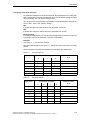
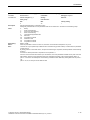
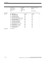
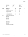
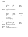
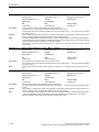
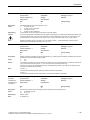
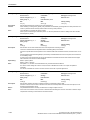
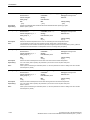
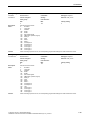
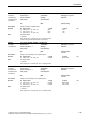
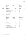
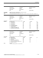
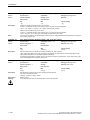
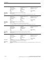
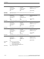
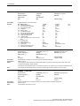
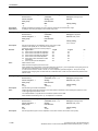
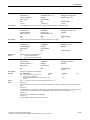
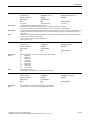
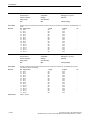
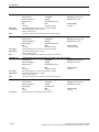
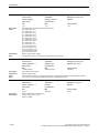
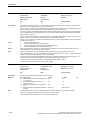
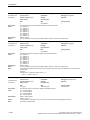
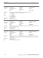
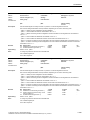
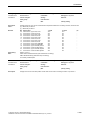
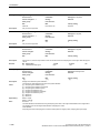
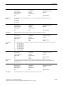
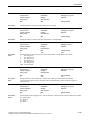
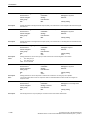
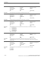
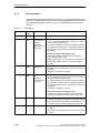
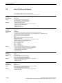
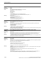
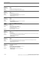
r0066
CO: Output frequency / f_outp
Access level: 3
Calculated: -
Data type: FloatingPoint32
Can be changed: -
Scaling: p2000
Data set: -
Units group: 2_1
Unit selection: p0505
Min
- [Hz]
Max
- [Hz]
Factory setting
- [Hz]
Description:
Displays the output frequency of the power unit.
Dependency:
Refer to: r0024
Note:
The output frequency is available smoothed (r0024) and unsmoothed (r0066).
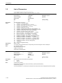
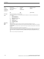
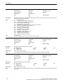
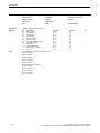
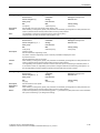
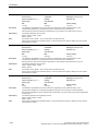
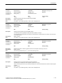
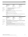
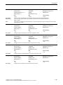
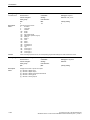
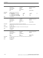
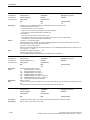
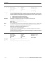
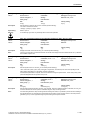
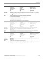
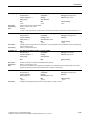
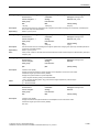
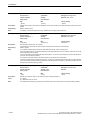
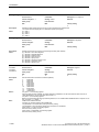
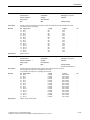
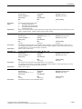
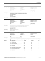
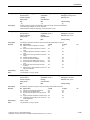
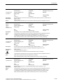
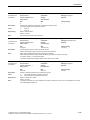
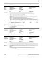
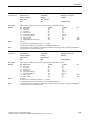
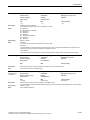
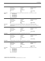
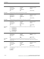
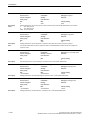
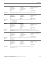
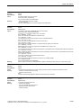
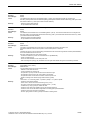
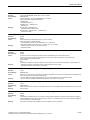
r0067
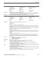
CO: Output current, maximum / I_outp max
Access level: 3
Calculated: -
Data type: FloatingPoint32
Can be changed: -
Scaling: p2002
Data set: -
Units group: 6_2
Unit selection: p0505
Min
- [Arms]
Max
- [Arms]
Factory setting
- [Arms]
Description:
Displays the maximum output current of the power unit.
Dependency:
The maximum output current is determined by the parameterized current limit and the motor and converter thermal
protection.
Refer to: p0290, p0640
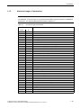
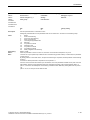
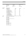
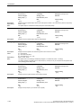
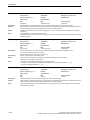
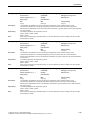
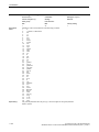
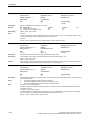
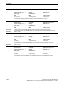
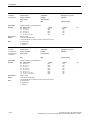
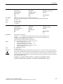
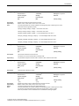
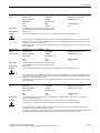
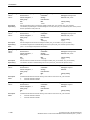
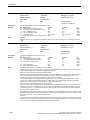
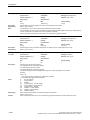
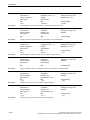
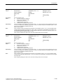
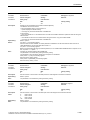
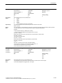
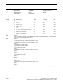
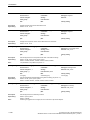
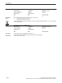
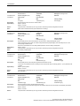
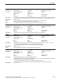
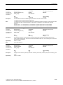
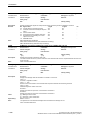
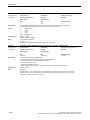
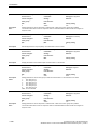
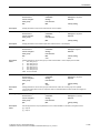
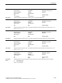
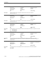
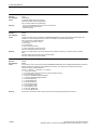
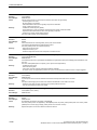
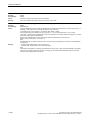
r0068[0...1]
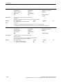
CO: Absolute current actual value / I_act abs val
Access level: 3
Calculated: -
Data type: FloatingPoint32
Can be changed: -
Scaling: p2002
Data set: -
Units group: 6_2
Unit selection: p0505
Min
- [Arms]
Max
- [Arms]
Description:
Displays actual absolute current.
Index:
[0] = Unsmoothed
[1] = Smoothed with p0045
Dependency:
Refer to: r0027
Notice:
The value is updated with the current controller sampling time.
Note:
Absolute current value = sqrt(Iq^2 + Id^2)
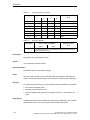
Factory setting
- [Arms]
The absolute value of the current actual value is available smoothed (r0027 with 300 ms, r0068[1] with p0045) and
unsmoothed (r0068[0]).
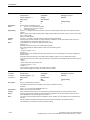
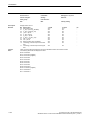
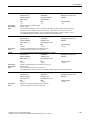
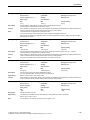
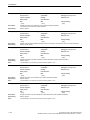
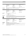
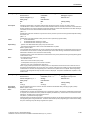
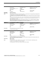
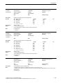
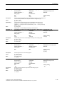
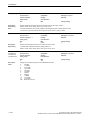
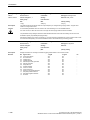
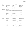
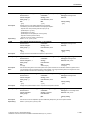
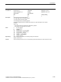
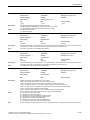
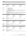
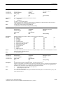
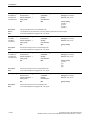
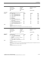
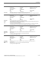
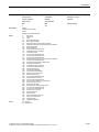
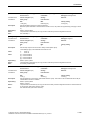
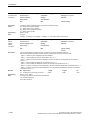
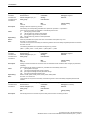
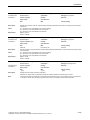
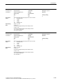
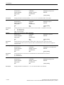
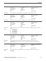
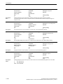
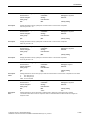
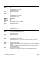
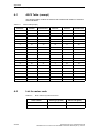
r0069[0...6]
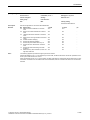
CO: Phase current actual value / I_phase act value
Access level: 4
Calculated: -
Data type: FloatingPoint32
Can be changed: -
Scaling: p2002
Data set: -
Units group: 6_5
Unit selection: p0505
Min
- [A]
Max
- [A]
Description:
Displays the measured actual phase currents as peak value.
Index:
[0] = Phase U
[1] = Phase V
[2] = Phase W
[3] = Phase U offset
[4] = Phase V offset
[5] = Phase W offset
[6] = Total U, V, W
Note:
Factory setting
- [A]
In indices 3 ... 5, the offset currents of the 3 phases, which are added to correct the phase currents, are displayed.
The sum of the 3 corrected phase currents is displayed in index 6.
© Siemens AG 2011 All Rights Reserved
SINAMICS G120 Control Units CU240B/E-2 Parameter Manual (LH11), 01/2011
1-37