Download Musicam Roadrunner Specifications
Transcript
RoadRunner U S E R S G U I D E Users Guide RoadRunner U S E R S G U I D E MUSICAM USA Users Guide for Software Revision 2.0 MUSICAM USA Corporate Computer Systems, Inc. 670 North Beers Street, Building 4 Holmdel, NJ 07733 USA Phone (732) 739-5600 • Fax (732) 739-1818 http://www.musicamusa.com First Printing: February, 2000 MUSICAM USA Part Number 605500M i RoadRunner U S E R S G U I D E Terminal Adapter TA101 Configuration 19 Switch Type (North America and Germany Only) 20 Service Provider ID (SPID) Number (North America Only) 21 Identification (ID) Number (North America Only) 22 Multiple Subscriber Number (MSN/LDN — Europe Only) 22 Local Check (North America Only) 22 LLC State 22 Sub Address, EAZ (Germany) And Interface Mode 22 Reset 23 Terminal Adapter TA201 and TA301 Configuration for North America24 Selecting Country and Switch Type 24 Service Provider ID (SPID) Number 25 Identification (ID) Number 25 LLC 25 Reset 26 Terminal Adapter TA201 Configuration, Non-North American Operation 26 Selecting Country and Switch Type 26 LDN / MSN Number 26 LLC (Low Level Command) State (UK Only) 27 Sub-Address and Interface Mode 27 Reset 27 Other TA Parameters — Auto Answer, Auto Reconnect, Dial Time Out and Redial Attempts 28 Terminal Adapter TA201/TA301 Software Version 29 Using TA Configuration Memory 29 Saving Current TA Configuration29 Loading Stored Configurations 29 Stored Configuration Table Maintenance 30 Audio I/O and Level Adjustments 30 Audio Output Muting 31 Loopback Testing 31 Table of Contents Introduction 1 Key Features CODEC Compression Algorithms ISO/MPEG Layer III MUSICAM and ISO/MPEG Layer II G.722 Broadcast Capabilities Ancillary Data 3 4 4 Unpacking and Installing RoadRunner Connections 6 6 RoadRunner Overview Front Panel Connectors and Controls Rear Panel Controls and Connectors 8 4 5 5 5 8 9 Digital Interface Module 11 Installing the Digital Interface Module 11 RS422/RS449/RS530 and X.21 Using the DIF101 Digital Interface 12 V.35 Using the DIF102 Digital Interface 13 ISDN Using the TA101 Terminal Adapter 13 ISDN Using the TA201 Terminal Adapter 14 ISDN Using the TA301 Terminal Adapter 14 RoadRunner Setup 16 Menu Navigation Using the Keypad and Display 16 Selecting A Digital Interface Module (DIF) 18 TA Configuration 18 The Session Encoder and Decoder Algorithms 1 33 33 RoadRunner U S E R S G U I D E Quick Setup Quick Status Advanced Setup Decoder Configuration Setup Using Quick Configurations And Speed Dials Pre-Programmed Quick Configurations Receiving Calls Manual Dialing Speed Dialing Call Termination 35 37 38 38 40 41 44 45 45 46 Advanced Features 47 Advanced Encoder and Decoder Features 47 Broadcasting 47 Advanced Encoder and Decoder Settings 48 Error protection (ACE) 48 Sine Detector 49 Header and Status Bits 49 Decoder Mute 50 Speed Dial Table Maintenance 50 Creating Quick Configurations and Speed Dial Entries Using System Snapshots 50 Editing an Existing Entry 51 Manual Entry of Quick Configuration or Speed Dial 52 Deleting Quick Configurations and Speed Dial Entries 53 Prima Logic Language 54 Ancillary Data 55 Remote Control 56 Far-End Remote Control 57 Opto Inputs And Relay Outputs 58 Hot Keys 58 Software Maintenance and Upgrading 59 Rebooting and Resetting Factory Defaults 60 Keypad Beeper and Display Brightness 61 Troubleshooting Audio Problems No Audio in Loopback No Audio when Connected to Another Codec Echo Connection Problems (ISDN) Connection Problems (Non-ISDN) TA101 Setup TA201 / TA301 Setup Control Problems 62 62 62 Appendix A — DIF Pin Out DIF 101— X.21 / RS449 DIF 102— V.35 73 73 73 63 65 65 67 68 70 71 Appendix B — Rear Panel Pin Outs 74 Relay outputs and opto-inputs (future): 74 Remote Control / Software Upgrade:74 Appendix C — ISDN Ordering and Provisioning 75 North American ISDN Ordering Contacts 75 North American ISDN Provisioning 75 FAX-PAGE 1 76 AT&T 5ESS Custom 76 FAX-PAGE 2 77 AT&T 5ESS - National ISDN 1 77 FAX-PAGE 3 78 AT&T 5ESS — Custom 78 AT&T 5ESS — National ISDN 78 Northern Telecomm DMS-100 BC-35 National ISDN 1 79 FAX-PAGE 4 79 FAX-PAGE 5 80 Northern Telecomm DMS-100 BC-35 National ISDN 1 80 Appendix D — Menu Tree –ISDN Operation 81 Appendix E — Warranty 2 82 RoadRunner U S E R S 1 Chapter G U I D E Introduction R oadRunner from MUSICAM USA contains the latest in technologies to bring you the best possible combination of features and performance available from any portable codec. Inside its rugged but lightweight enclosure, the RoadRunner contains a full-featured monaural audio mixer with two microphone inputs and a third input switchable between microphone and line levels. The analog audio section also contains a wide array of outputs: two individually adjustable headphone outputs, plus two unbalanced and one balanced line level output. RoadRunner’s digital section contains the widest selection of compression algorithms available in any portable codec. RoadRunner’s premier coding algorithm is MUSICAM, MUSICAM USA’s fully compatible enhancement to the ISO/MPEG Layer II encoding standard. Industry standard ISO/MPEG Layer III as well as G.722 are also included. RoadRunner can send and receive up to 20 kHz monaural audio transparently over digital transmission systems and is compatible with more codecs than any other similar device. RoadRunner can send the same audio program to two locations simultaneously. RoadRunner also contains ample memory to support upgrades to its algorithm suite and operating system as developments and improvements occur. You can even make software upgrades in the field, without having to return the RoadRunner to the factory. RoadRunner also contains powerful ancillary data features that enable bi-directional RS232 ancillary data, up to 4 relay contact closures and far-end remote control when connecting to another compatible codec. These ancillary data features are available with all algorithms except G.722. In addition, the powerful Logic Language offers a large selection of automated functionality programming that is unavailable from any other manufacturer. RoadRunner offers more connection options than any other portable codec. With a plug-in ISDN terminal adapter (RoadRunner’s standard 1 RoadRunner U S E R S G U I D E configuration), RoadRunner can connect directly to another ISDN codec at bit rates from 56 to 128 kb/s. RoadRunner also accepts any of the digital interface modules available from MUSICAM USA, and can be used over any digital facility that accepts V.35, X.21 or RS422 interfaces, in addition to ISDN. RoadRunner’s built-in auto-dialer can be used to make all connections when using any one of MUSICAM USA’s available ISDN terminal adapters. RoadRunner’s speed dial directory holds up to 256 entries. Each entry not only holds the numbers to dial, but also all configuration and connection information, making the RoadRunner easy to use with any connection type. 2 RoadRunner U S E R S 2 Chapter G U I D E Key Features R oadRunner is a complete package. It is housed in a rugged case and includes a foldaway handle. The complete RoadRunner package weighs less than 9.5 pounds (4.3 kg). Inside the RoadRunner case is a full featured 3-channel monaural audio mixer, an 18-bit A-to-D converter, a multi-algorithm codec, a slot for available plug-in digital interface device (an ISDN terminal adapter is supplied as standard), an auto-dialer, international AC and DC power supplies, and a powerful command processor. If you choose, you can connect your RoadRunner to any digital transmission system through available ISDN, X.21, V.35 or RS422 digital interface modules. RoadRunner uses state-of-the-art compression technologies to provide bi-directional broadcast quality monaural audio over a single 56 or 64 kb/s line. In addition, the RoadRunner can provide bi-directional 20 kHz monaural audio transparently over a single ISDN line at 112 or 128 kb/s. Ancillary data is supported at all bit rates with any MPEG algorithm. RoadRunner is easy to use. The RoadRunner front panel controls have been kept to a minimum, are simple to use, and are clearly labeled. The front panel controls include mixing levels for three inputs (two microphone and one switchable mic/line) and individual local and return level adjustments for two separate headphone outputs. All audio connections are made through industry standard connectors, logically located on the front and rear panels. Two balanced XLR microphone inputs are located on the front panel, as are two standard ¼” headphone jacks. An additional balanced input, switchable between microphone and line levels, is located on the rear panel. Also on the rear panel is an XLR balanced line level output and two ¼” unbalanced local and return audio outputs, ideal for PA feeds, recording, etc. 3 RoadRunner U S E R S G U I D E The RoadRunner can be equipped with any of the Digital Interface Modules available from MUSICAM USA. Available modules include internal Terminal Adapters (with or without built-in NT-1), V.35, X.21, RS530 or RS422. Front panel indicators include Power, On line, Norm (signal level) and Clip (over level). There are also four Cue LEDs indicating the state of the internal relays. The front panel keypad can be used to access all functions of the RoadRunner and built in Terminal Adapter, and is also used as the dial keypad. A backlit display with adjustable contrast provides menu, maintenance and dialing displays. Since RoadRunner features and audio quality are implemented in software, rather than hardware, the RoadRunner can be upgraded in the field should improvements become available. Software can be downloaded directly from our Web Site (www.musicamusa.com) or we can send you an upgrade kit. This prevents your RoadRunner from becoming obsolete. CODEC Compression Algorithms There are currently three coding algorithms used in the RoadRunner. Each has its advantages and disadvantages. Which algorithm you use depends on a number of factors, including desired audio quality, delay and compatibility with other codecs. ISO/MPEG Layer III ISO/MPEG Layer III can provide full duplex, 15 kHz monaural audio using only one 56 or 64 kb/s ISDN ‘B’ channel. When using 112 or 128 kb/s, transparent 20 kHz monaural audio is possible. The inherent drawbacks of this algorithm are the long coding delay times and poor cascading characteristics. In addition, post processing may highlight some artifacts. MUSICAM and ISO/MPEG Layer II The premier coding algorithm used in RoadRunner is MUSICAM, MUSICAM USA’s encoding enhancement to the ISO MPEG Layer II algorithm. MUSICAM encoding is fully compatible with all MPEG Layer II decoders, and since the enhancements area part of the encoder, any Layer II decoder will sound better when connected to a 4 RoadRunner U S E R S G U I D E RoadRunner. MUSICAM can deliver full duplex, 10.5 kHz monaural audio on one ISDN ‘B’ channel. When using 112 or 128 kb/s, transparent 20 kHz monaural audio is possible. Although a narrower bandwidth at 56 and 64 kb/s than MPEG Layer III, audible advantages are higher transparency, lower delay, less noticeable artifacts and better results when cascading. At 112 and 128 kb/s, MUSICAM offers transparent monaural audio and better cascading than either standard ISO/MPEG Layer II or Layer III. G.722 G.722 is one of the earliest audio coding algorithms to be standardized. G.722 is a relatively simple algorithm based on ADPCM (Adaptive Predictive Pulse Code Modulation) offering full duplex, 7.5 kHz audio over a single ‘B’ channel. The essential advantages of G.722 are its compatibility with most other codecs and very low delay times. The main disadvantages are its limited audio fidelity, poor signal-to-noise ratio and poor cascading. Broadcast Capabilities The RoadRunner can be configured to send the same audio program to two different locations simultaneously. In addition, the RoadRunner’s decoder can receive the return audio from both locations, and you can easily switch to monitor the return audio from either location. You can use any supported algorithm, and can even use different algorithms for the send and return audio. For example, a typical application involves sending high quality Layer III audio to the studio from the remote location, but low delay G.722 can be used for the return audio. Ancillary Data A bi-directional RS232 data path is provided for end-to-end ancillary data communications when using any MPEG algorithm. Baud rates up to 38,400 are supported. 5 RoadRunner U S E R S G U I D E 3 Chapter Unpacking and Installing Y our RoadRunner comes with an AC line cord and an RJ-45 jumper cable if an ISDN terminal adapter is installed. An appropriate interface cable, available from MUSICAM USA, may be required if a non-TA module is installed. An optional carrying case is available. Unpack your RoadRunner and plug it in to an appropriate power source. Please note that the RoadRunner has “World” AC and DC power supplies, and can be used anywhere without changing voltage settings. RoadRunner can operate in any position, and may be stacked or shelf mounted if desired. However, note that RoadRunner is fan cooled, and the rear mounted fan should not be blocked. Your RoadRunner is shipped to you in Loopback Mode. When in this mode, you can test all audio input and output connections. When your RoadRunner is in the loopback mode, and all audio connections have been made properly, you should hear any audio input to the RoadRunner at the output of the RoadRunner. Please remember that for normal operation, the RoadRunner must not be in loopback mode. RoadRunner Connections RoadRunner‘s connection to the digital transmission medium is made through a Digital Interface Module (DIF). The RoadRunner supports one digital interface module that plugs into a slot in the rear panel. Two types of DIFs are available, Terminal Adapter (TA) and non-TA. TAs connect directly to your ISDN line and allow dialing directly from the RoadRunner keypad. Non-TA type modules can connect to external terminal adapters or most other digital facilities, such as dedicated lines, fractional T1 or satellite systems through appropriate interfaces. 6 RoadRunner U S E R S G U I D E MUSICAM USA offers three different TA modules, the TA101, TA201 and TA301. The TA101 and TA201 both provide an ‘S/T’ interface and require an external network interface device (NT-1) for use in North America. Elsewhere, the NT-1 is provided by the phone company, and an external NT-1 is not required. The TA301 provides a ‘U’ interface through its built-in NT-1 and therefore can be used only in North America. Connect the ISDN line to your internal terminal adapter (if so equipped). Be sure that there are no alarm conditions present on the terminal adapters or the NT-1. There should be no flashing LEDs or other alarm indications for proper operation. The TA201 and TA301 terminal adapters have sanity LEDs that can be observed from the back of the RoadRunner. The green LED must be solid ON for proper operation. If using an external NT-1 with your terminal adapter, the ‘U’ interface (the wall connector) requires a 2-conductor cable. The ‘S/T’ interface (the RoadRunner side) requires an 6-conductor cable. Two non-TA digital interfaces are also available for the RoadRunner. The DIF101 interface is used for connecting transmission systems using X.21, RS422, RS449 or RS530 interfaces. The DIF102 interface connects to transmission systems using the V.35 protocol. All audio inputs and outputs are through industry standard connectors located on the front and rear panels. Two balanced XLR microphone inputs are located on the front panel as are two standard ¼” headphone jacks. An additional balanced input, switchable between microphone and line levels, is located on the rear panel. Also on the rear panel is an XLR balanced line level output for received audio from the far end unit and two ¼” unbalanced local and return audio outputs to feed recorders, PA systems, etc. The four relay outputs and optically isolated inputs are accessed through the DB-25 connector, and there is a DB-9 connector for ancillary data, remote control and software upgrades. Connectors for AC power (100-240 VAC, 50/60 Hz) and 12 VDC power are also located on the rear panel, as is the power switch. 7 RoadRunner U S E R S 4 Chapter G U I D E RoadRunner Overview Front Panel Connectors and Controls 1 MICROPHONE INPUTS Two balanced microphone inputs 2 MICROPHONE INPUT LEVEL CONTROLS Adjusts level and mix for two microphone inputs 3 HEADPHONE 1 LEVEL CONTROLS Adjusts send & return levels for headphone 1 4 HEADPHONE 2 LEVEL CONTROLS Adjusts send & return levels for headphone 2 5 BACK-LIT LCD DISPLAY Displays all control functions and modes 6 INPUT 3 LEVEL CONTROL Adjusts level of mic/line input 3 7 HEADPHONE 1 OUTPUT 1/4” Headphone output 8 HEADPHONE 2 OUTPUT 1/4” Headphone output 9 RELAY STATUS INDICATORS LED relay and cue status indicators 10 STATUS INDICATORS LED RoadRunner status indicators 11 NAVIGATION KEYS LCD Menu navigation keypad 12 ALPHANUMERIC KEYPAD Configuration and dialing keypad 13 DIAL KEYS Controls all dialing functions and directory maintenance 14 FUNCTION KEYS Hot keys for one-button functions 8 RoadRunner U S E R S G U I D E Rear Panel Controls and Connectors With certain external phantom power supplies it may be necessary to lift the ground lead (shield) from one side of the cable. 1 LINE OUTPUT Balanced, fixed line level return audio output 2 INPUT 3 Microphone or line input 3 3 INPUT SELECTOR Microphone or line level select for input 3 4 UNBALANCED RETURN AUDIO OUTPUT Unbalanced line level return audio output 5 UNBALANCED LOCAL AUDIO OUTPUT Unbalanced line level local audio output 6 RS232 CONTROL AND ANCILLARY DATA DB-9 connector for ancillary data, remote control and software upgrades 7 RELAY OUTPUTS DB-25 connector for contact closure I/O (future) 8 DIF SOCKET Slot for digital interface module or ISDN terminal adapter 9 FAN Cooling fan for reliable operation 10 DC POWER INPUT Input for DC power 11 POWER CONNECTOR AC Mains power connector 12 POWER SWITCH Power switch You can connect a professional quality low impedance microphone directly to either XLR microphone input on the front panel. A microphone can also be connected to the mic/line input on the rear panel, setting the level switch accordingly. High impedance microphones, or microphones with other than XLR connectors must use an external matching transformer or adapter. Phantom power is not provided. Balanced monaural line level audio is input through the XLR 9 RoadRunner U S E R S G U I D E Input 3 connector on the rear panel, setting the input level switch accordingly. Mic/Line mixing is accomplished using the three input level controls located on the front panel. When audio is present, adjust the levels so that the green ‘NORM’ indicator illuminates and the red ‘CLIP’ indicator does not. It is recommended that the input level be turned down if an input is not connected. Two sets of headphones with ¼” jacks can be used without adapters. When stereo headphones are used, the output will be monaural, to both ears. Do not use monaural headphones with 2-conductor plugs. The audio source to the headphones, local or return audio, is adjusted using the two monitor level controls located above each headphone output. Level adjustments for each headphone are independent. Balanced Line level return audio (audio from the far-end) is available through an XLR connector, and unbalanced line level local and return audio is available through two ¼” phone jacks. All output levels are fixed at 0 dBu relative to input levels (no insertion gain/loss). A 9-pin connector for RS232 ancillary data, remote control and software maintenance is included, as is a 25-pin connector for the four optically isolated inputs and relay outputs. In addition, one slot can hold any of the plug-in digital interface modules available from MUSICAM USA. Available modules include ISDN Terminal Adapters, RS422, X.21, and V.35 interfaces. Although primarily an ISDN device, you can also use the RoadRunner with other digital transmission systems, such as Switched-56, dedicated lines, fractional T-1 and satellite systems using the appropriate digital interface module. The RoadRunner can be used with 12 VDC or AC power. The universal AC power supply needs no jumpers, and works with 94 - 250 VAC, 50 or 60 Hz. Power consumption is approximately 40 Watts. Please note that the RoadRunner does require forced-air cooling, and that the rear mounted cooling fan should not be blocked. The RoadRunner has a rich set of remote control commands that allow you to control it from an attached terminal or computer. A separate RoadRunner Remote Control Manual is available from MUSICAM USA upon request. 10 RoadRunner U S E R S 5 Chapter G U I D E Throughout the remainder of this manual, a shorthand notation for menu navigation will be used. As an example, the notation <Maint><Dig I/F><Type> means: use the cursor keys to scroll to ‘Maint’ and press ENTER. Then scroll to ‘Dig I/F’ and press ENTER, finally, scroll to ‘Type’ and press ENTER. Digital Interface Module Y ou can skip this chapter if your digital interface module or terminal adapter has been factory installed. Installing the Digital Interface Module A digital interface module is required to use your RoadRunner with a transmission system. Only one DIF module can be installed in the RoadRunner at a time. If you are using a DIF101 or DIF102 module for RS422, X.21 or V.35 interfaces use the appropriate cables, available from MUSICAM USA. All DIFs are installed in the slot in the rear of the RoadRunner. You should make certain that the module is installed correctly, not forced and has been securely fastened using the provided screws. You should not attempt to operate the RoadRunner if the DIF has not been properly installed and secured. Once installed, the DIF module and interface type must be selected on the RoadRunner menu for proper operation: <Maint><Dig I/F><Type> 11 RoadRunner U S E R S G U I D E RS422/RS449/RS530 and X.21 Using the DIF101 Digital Interface The RS422 interface specification defines only the electrical voltages at the interface and leaves the pin-out and meaning of the pins to the hardware designer. The RS449 interface specification utilizes the electrical specifications of RS422 but specifies a mechanical connector. RS449 equipment is therefore electrically compatible with the RoadRunner RS422 interface when an appropriate adapter cable is used. RS449 also specifies numerous control signals besides clock and data, which are not used by the RoadRunner. The RoadRunner RS422 interface pin-out is specified in Appendix A. The RS422 interface also has a separate clock for the transmitted and received data. The RS422 interface can also echo the transmitter clock. If the terminal equipment clocks the encoder data with the echoed clock, the RoadRunner may be located up to 4000 feet (1219 meters) from the terminal equipment without concern for encoder-to-clock skew. The X.21 (also known as RS530) interface specification is, in general, a very complex specification. The general specification allows a mechanism for communication between the customer equipment and the network. This communication path can be used for things such as dialing. A sub-set of the specification, called the leased circuit, used here, restricts the interconnection to only clock and data and a very simple control signal. The mechanical connector required is the DB15 with the pin-out specified in Appendix A. The electrical specification for X.21 is identical to those of RS422. The X.21 interface has only one clock for both transmit and receive signals. Since the X.21 uses the RS422 electrical interface, the RoadRunner can use the same connector for both interfaces. In the case of the X.21 interface, the single clock is used internally for both transmit and receive timing. To change the hardware configuration of the DIF101 interface card between X.21 and RS422/RS449, change the position of jumper J4 on the interface module. The jumper on positions 1 and 2 sets X.21 operation, and when on positions 2 and 3, the card is set for RS422/RS449 operation. Once the DIF101 module is installed, select the appropriate interface type from the RoadRunner menu: 12 RoadRunner U S E R S G U I D E <Maint><Dig I/F><Type><type> where type can be either X.21, X.21XTA or RS422. Select RS422 when connecting the RoadRunner to any RS422 network interface. When connecting to any X.21, RS449 or RS530 interface, select X.21XTA if the external network interface device recognizes a changeof-state of the DTR/CON line. This enables the RoadRunner to terminate the connection when you press the END button. Otherwise, select X.21 as the interface type. V.35 Using the DIF102 Digital Interface Each interface defines a voltage level for each of the signals. In the case of V.35 and X.21, a connector type is defined as well. The large, rectangular block connector defined in the V.35 specification is not used by the RoadRunner because of its size. Instead, a smaller DB15 connector is used. In the case of the V.35 interface, the RoadRunner conforms to the electrical specification but requires an adapter cable to convert the DB15 connector to the connector specified in the V.35 specification. The connector and the pin-out chosen for the V.35 interface in the RoadRunner are a common deviant found in many systems. An adapter cable is available from MUSICAM USA or distributors, or can be made following the diagram found in Appendix B. It is important to remember that V.35 has a separate clock for transmitted and received data. Once the DIF102 module is installed, select the appropriate interface type from the RoadRunner menu: <Maint><Dig I/F><Type><type> where type can be either V.35 or V.35XTA. When connecting to any V.35 interface, select V.35XTA if the external network interface device recognizes a change-of-state of the DTR/CON line. This enables the RoadRunner to terminate the connection when you press the END button. Otherwise, select V.35 as the interface type. ISDN Using the TA101 Terminal Adapter The TA101 Terminal Adapter plugs directly into the RoadRunner and provides an ‘S/T’ interface to ISDN. The S/T interface requires an NT- 13 RoadRunner U S E R S G U I D E 1, which must be provided by the user for North American operation. Elsewhere, the service provider supplies the NT-1. Since every country requires slightly different ISDN control and signaling information, the TA101 TA requires different ROM chips for different countries. If you have specified the country in which you will be using the RoadRunner when ordering, your TA101 will have the correct ROM chip installed. Please check with your local distributor, CCS Europe or MUSICAM USA if you will be taking your RoadRunner to foreign countries. Configuring the TA101 is discussed in later sections. Once the TA101 module is installed, select the appropriate interface type from the RoadRunner menu: <Maint><Dig I/F><Type><TA101> ISDN Using the TA201 Terminal Adapter The TA201 Terminal Adapter plugs directly into the RoadRunner and provides an ‘S/T’ interface to ISDN. The S/T interface requires an NT1, which must be provided by the user for North American operation. Elsewhere, the service provider supplies the NT-1. The TA201 is pre-programmed with the ISDN configurations for all countries, and can be used everywhere without the need for changing ROM chips. Country selection is made in from the RoadRunner’s menu, and will be discussed later. Once the TA201 module is installed, select the appropriate interface type from the RoadRunner menu: <Maint><Dig I/F><Type><TA201> ISDN Using the TA301 Terminal Adapter The TA301 Terminal Adapter contains a built-in NT-1, providing a ‘U’ interface. Since outside North America, the NT-1 is supplied by the provider, and the network provides the ‘S/T’ interface, the TA301 can be used only in North America. Configuring the TA301 will be discussed later. Once the TA301 module is installed, select the appropriate interface type from the RoadRunner menu: 14 RoadRunner U S E R S G U I D E <Maint><Dig I/F><Type><TA301> 15 RoadRunner U S E R S 6 Chapter G U I D E RoadRunner Setup A fter applying power to the RoadRunner, a boot sequence executes for approximately 30 seconds. This boot sequence initializes the DIF, digital signal processors, and control processor. After the boot sequence completes, the LCD RoadRunner 2.00 display should look like this: [Status] Operati If a Terminal Adapter is installed in the RoadRunner, the ON LINE lamp may come on during the boot sequences but should extinguish upon completion. If the ON LINE lamp stays on after the boot sequence completes (when equipped with an internal terminal adapter), re-boot the unit by turning the power off and on again. If a V.35 or X.21 interface is used, and an external TA (V35XTA or X.21XTA) is not selected, the ON LINE lamp will remain illuminated. The RoadRunner is fully configured and controlled using the built-in keypad and display. In addition, a full set of remote control commands is included so that your RoadRunner can be operated from a PC or terminal. The following sections discuss configuration and programming using the internal keypad. The remote control commands required for each operation are not included in this Users Guide. Complete remote control command syntax and options for each command is found in the RoadRunner Remote Control Manual, available upon request from MUSICAM USA or on-line at www.musicamusa.com. Menu Navigation Using the Keypad and Display All RoadRunner functions can be accessed using the soft-touch keypad and LCD display. 16 RoadRunner U S E R S G U I D E The following discussion of menu navigation is based on the basic keypad and display as shown in the following figure. The top line of the display is for information and prompts. The bottom line is for menu choice selection and information entry. To use the keypad and display, press the arrow keys to move the cursor (the [ ] brackets) to the desired menu selection. Press the ENTER key to execute the selection or move down to the next menu level. Pressing the ⇑ (up arrow) at any time brings you up one menu level. At any given time, only a limited number of selections may be visible on the display. By using the ⇐ and ⇒ (left and right) arrow keys, the display can be scrolled to show all possible options and selections. RoadRunner 2.00 [Status] Operati ! The alphanumeric portion of the keypad is used for entering information and for dialing. Each of the 12 keys associated with the alphanumeric portion of the keypad represent up to four different characters. Multiple presses of the same key select different characters. note: Please note: the QZ1 key is also the space key. Spaces are not entered using multiple presses of the right-arrow key. The left and right arrow keys are used in conjunction with the alphanumeric keys to move the cursor to the desired position. After the desired character string has been formed, pressing the ENTER key executes or enters the string. In the discussions that follow, the printed sequence <X><Y><Z> will be used as shorthand to mean: Use the arrow keys to move the cursor to ‘X’ and press ENTER, then use the arrow keys to scroll to ‘Y’ and press ENTER, finally, scroll to ‘Z’ and press ENTER . The keys under the ‘DIAL’ label are used to enter and execute dialing functions such as direct dialing, speed dialing, directory maintenance and call termination. The last column of keys are ‘Hot’ keys. Pressing any one of these keys will execute one of the pre-programmed or user 17 RoadRunner U S E R S G U I D E programmed one-button functions. These four keys can also be set up to close relay contacts on a far-end codec or to execute any remote control or Logic Language command. ! Selecting A Digital Interface Module (DIF) note: If the DIF was not factory installed, or if you change DIFs, you need to select the Digital Interface the first time you use the RoadRunner with that DIF. Once a DIF has been physically installed, you must set the RoadRunner to recognize the module. From the keypad, use the sequence: <Maint><Dig I/F><Type><Type> and scroll through the menu to select the installed interface. The choices are: TA101, TA201, TA301, X.21, X.21XTA, V.35, V.35XTA and RS422. Select the appropriate interface and press ENTER. You can also use the remote control command CIF from a terminal or computer. Select V.35XTA or X.21XTA only if your external TA is capable of recognizing DTR or CON signals for call termination. This allows you to terminate a connection from the front panel of the RoadRunner. You can also toggle the sense of the DTR line using the <DIFx01><DTR/CON> sequence. If your external TA cannot recognize these signals, then select V.35 or X.21. TA Configuration ! It is necessary to configure a Terminal Adapter each time you connect your RoadRunner to a different ISDN circuit. note: Three different TAs are available for use in the RoadRunner. All must be configured properly for use with ISDN, and all require the user to have certain information, supplied by the ISDN service provider. The following information must be known before configuring any TA for use: North America: —Switch Type (National ISDN-1 or Custom) 18 RoadRunner U S E R S G U I D E —Switch software version if switch type is Custom —Switch manufacturer if type is National (for TA101 only) —SPID numbers for each ISDN ‘B’ channel Elsewhere: —Switch type (if required) —ETSI version —Sub address (if required) For TA201 and TA301 configuration for North America, skip to page 23, skip to page 24 for TA201 configuration elsewhere. Terminal Adapter TA101 Configuration The TA101 ISDN Terminal Adapter is no longer available in North America. Your RoadRunner does support, and will operate with a TA101 terminal adapter. ! note: The TA101 terminal adapter provides one ‘S/T’ interface for one ISDN BRI (2 x 64 kb/s) line. In North America, the Telco provides a ‘U’ interface; therefore, an external NT-1 must be used between the RoadRunner and the wall jack. Elsewhere, the Telco provides an ‘S/T’ interface and an external NT-1 is not needed. The TA101 requires country specific ROM chips for use in different countries. Please contact MUSICAM USA, CCS-Europe or your local distributor for information if you plan to take your RoadRunner to a different country. Probably the most confusing aspect of ISDN codecs is configuring the Terminal Adapter for the ISDN in your area. This is especially true in North America, where there are several local ‘flavors’ of ISDN that are all provisioned differently. Elsewhere, configuration of the terminal adapter may be as simple as insuring the proper ROM chip is installed for the country where the RoadRunner is being used. In North America, the ISDN service provider must supply certain information to correctly configure the TA101 Terminal adapter: 19 RoadRunner ! note: U S E R S G U I D E • Switch Manufacturer, Telecom. • ISDN ‘flavor,’ e.g., National ISDN or Custom Point-to-Point. Please note that the TA101 terminal adapter will not work with AT&T Custom Point-to-Multipoint nor will it work with AT&T National ISDN software revision 5E9.1. • Service Provider Identification Numbers (SPID numbers). National ISDN always requires SPID numbers, some locations using Custom Point-to-Point may not require SPID numbers. If SPID numbers are required, most areas use two, but some implementations require only one (are you confused yet?) e.g. AT&T, Seimens, Northern Switch Type (North America and Germany Only) It is necessary to tell the TA101 what type of switch protocol is being used at the Telco central office. The ISDN service provider will give this information to you. You only need to set the switch type once for each TA since the switch governs both. Use the menu branch: <TA101><Setup><Sw Type> then select the appropriate switch type. The CSW command is used for setting the switch type from a terminal. 5E6 and 5E8 switch types are used only for Custom Point-topoint ISDN. Use NTI for Northern Telecom switch and NI-1 for all other National ISDN ! In North America, four switch types are available: • • • • 5E6 is used for AT&T Custom Point-to-Point ISDN version 5E6 or earlier. This selection is not used for AT&T National ISDN, regardless of version number. 5E8 is used for AT&T Custom Point-to Point ISDN version 5E8 or later. This selection is not used for AT&T National ISDN, regardless of version number. NTI is used when the switch is a Northern Telecom DMS-100 switch NI1 is used for all other National-ISDN-1 implementations, including AT&T. German users have three choices: DSS1, 1TR6 and AUTO (AUTO will not work if a PBX is used). Contact CCS-Europe for information on which to use in your area. note: Special Notes for Switch Type 5E6, 5E8 and AT&T 5E9.1 (North America Only). Point-to-Multipoint is not supported. 20 RoadRunner U S E R S G U I D E If your service provider tells you that the switch type is an AT&T 5ESS Custom Point-to Point with software version 6 or earlier, you cannot enter a SPID and ID number since these are not supported. Since SPID and ID numbers are not entered, you must tell the RoadRunner not to look for them, by setting Local Check to NONE, using the menu sequence <TA101><Setup><Lcl Chk><None> or the CLC command. If your service provider says your 5ESS switch is running software version 5E9.1 in Custom Point-to-Point configuration, they may give you SPID numbers. On the RoadRunner, select switch type 5E8, do not enter the SPID numbers, but enter the ID numbers and local check values. A TA reset may or may not result in a “SP1 BAD SP2 BAD” message. When dialing, ‘1 + area code’ dialing is required, even for local calls. If your service provider says your 5ESS switch is running software version 5E9.1 in National ISDN configuration, you must contact MUSICAM USA technical support. ! note: Service Provider ID (SPID) Number (North America Only) For most areas in North American, the TA must be told the SPID number of the calling ISDN line; that is, the line connected to the RoadRunner. The ISDN service provider in your area provides this number. It is important to remember that every time the RoadRunner is moved, or whenever there is a change in the ISDN line, or even area code changes, the SPID and ID number, switch type and possibly other parameters for the TA setup must be updated. You can store up to 20 ISDN SPID and location configurations for later recall. To set the SPID number using the keypad, go down the branch <TA101><Setup><SPID> select the ‘B’ channel number, 1 or 2, and enter the provided SPID number. Please note that each TA supports 2 basic rate ISDN ‘B’ channels, so if your service provider gave you two SPID numbers, you must enter both of them, one for each ‘B’ channel. Use the CSI command to set the SPID number from a terminal. 21 RoadRunner U S E R S G U I D E Identification (ID) Number (North America Only) If you are required to use two SPID numbers, then you must use ID numbers. For the TA101 terminal adapter, the ID number is just the last four digits of the seven digit ISDN line number connected to the RoadRunner. Use the <TA101><Setup><ID> branch, and enter the ID for each ‘B’ channel. You can use the CLD command from a terminal. Multiple Subscriber Number (MSN/LDN — Europe Only) If you have selected the DSS1 switch type in Germany, then MSNs must also be used. Use the <TA101><Setup><ID> or use the CLD command. Local Check (North America Only) If you are required to use ID numbers, you must also set the Local Check values. Local check tells the TA101 which internal buffers to check for the ID number. To set this parameter, branch down <TA101><Setup><Lcl Chk> and select the ‘B’ channel, then enter the number of the buffer that contains the ID number. You can use the CLC command from the terminal. The Local Check values for ‘B’ channel 1 must be ‘T5’ and for ‘B’ channel 2 must be ‘T6’. If IDs are not used, local Check must be set LLC State In some areas of the United Kingdom, it may be necessary to toggle the state of the Low Level Command mode. Use the LLC command sequence <TA101><Setup>< LLC> or the CLL command for this if you are having connection problems. In most other locations, including North America, leave the LLC state ON. Sub Address, EAZ (Germany) And Interface Mode The sub-address for an S/T interface TA (TA101) is set by the CSA command: <TA101><Setup><Sub addr> 22 RoadRunner U S E R S G U I D E This command is used when a RoadRunner is connected to a digital PBX. If the TA101 is directly connected to an NT1, then the sub-address should be set to 0. Subaddresses are generally not used in North America. In Germany, when using the 1TR6 switch type, subadresses are required. Use the CSA command to set the EAZ sub address. ! The CTF command, <TA101><Setup><I/F> note: sets the interface mode of the internal TA101. For North American operation with the TA101, the mode should always be set to IGNORE. For operation elsewhere, initially start with the mode set to IGNORE. If you have problems making or receiving calls, then set the mode to ACTIVE. Reset After the above parameters have been set, it is necessary to reset the TA101 Terminal Adapter. The CTR command, <TA101><Setup><Reset> is used to reset the internal terminal adapter and to check if the SPID and ID numbers have been entered correctly for North American operation. The reset process takes from 20 to 40 seconds to complete, and the response will be flash for 2 seconds on the top line of the LCD display. The following responses are possible: • • • • SP1 OK SP2 OK SP1 OK SP 2 BAD SP1 BAD SP2 OK SP1 BAD SP2 BAD SPID 1 and SPID 2 initialized properly SPID 1 initialized, SPID 2 did not SPID 1 did not initialize, SPID 2 did Both SPIDs did not initialize. If you require two SPID numbers, and if you get any response other than the first, your TA101 has not been configured properly and you will not be able to make or receive calls. If only one, or no SPID numbers are required, than any response may be OK. Try dialing and see if you can connect to another codec. If you get a bad response, or you cannot dial, please refer to the Troubleshooting Section before calling for assistance. 23 RoadRunner You can skip to the next section (Page 26) if you are using the TA201 outside North America. U S E R S G U I D E Terminal Adapter TA201 and TA301 Configuration for North America The TA201 terminal adapter provides one S/T interface for one ISDN BRI (2 x 64 or 2 x 56 kb/s) line. In North America, the Telco provides a ‘U’ interface, therefore an external NT-1 must be used between the RoadRunner and the wall jack. Elsewhere, the Telco provides an S/T interface and an external NT-1 is not needed. The TA201 contains all country specific configuration and provisioning information in memory, and there is no need to change ROM chips when using your RoadRunner in a different country. The TA301 is identical to the TA201 except that it contains a built-in NT-1 and connects directly to the ISDN ‘U’ interface provided in North America. RoadRunner units intended for use in North America will be shipped with the TA301 unless specified otherwise. Probably the most confusing aspect of ISDN codecs is configuring the Terminal Adapter for the ISDN in your area. This is especially true in North America, where there are several local ‘flavors’ of ISDN that are all provisioned differently. Elsewhere, configuration of the terminal adapter may be as simple as insuring the proper country is selected. In North America, the ISDN service provider must supply certain information to correctly configure the Terminal Adapter: Select 5ESS CUST only for AT&T Custom service. For 5ESS National ISDN, select NI1. • ISDN ‘flavor,’ e.g., National ISDN or Custom. • Service Provider Identification Numbers (SPID numbers). National ISDN always requires SPID numbers, but some locations using Custom ISDN may not require SPID numbers. If SPID numbers are required, most areas use two, but some implementations require only one. Selecting Country and Switch Type It is necessary to tell the TA what type of switch protocol is being used at the Telco central office. The ISDN service provider will give this information to you. You only need to set the switch type once for each TA since it is impossible to have different switch types for the individual ‘B’ channels in an ISDN line. Select <TAx01><Setup><N. America><Sw type> 24 RoadRunner U S E R S G U I D E then select the appropriate switch type, either National or AT&T Custom. Both the TA201 and TA301 are compatible with AT&T Custom Point-to-Multipoint ISDN service. The CCC command is used for selecting the country and the CSW command is used for setting the switch type from a terminal. ! note: Service Provider ID (SPID) Number For most areas in North America, the TA must be told the SPID number of the calling ISDN line, that is, the line to which the RoadRunner is connected. The ISDN service provider in your area provides this number. It is important to remember that every time the RoadRunner is moved, or whenever there is a change in the ISDN line, or even area code changes, the SPID and ID number, switch type and possibly other parameters for the TA setup must be updated. You can store up to 20 ISDN SPID location configurations for later recall. To set the SPID number using the keypad, go down the branch <TAx01><Setup><N. America><SPID> selecting the desired ‘B’ channel, and enter the SPID number. Please note also, that each TA supports 2 basic rate ISDN ‘B’ channels, so if your service provider gave you two SPID numbers you must enter both of them, one for each ‘B’ channel. Use the CSI command to set the SPID number from a terminal. Identification (ID) Number If you are required to use two SPID numbers, than you must use ID numbers. For the TA201 and 301, the ID number is just the 7 digit ISDN line number connected to the RoadRunner. Use the ! <TAx01><Setup><N. America><ID> branch, and set the ID’s for both ‘B’ channels from the keypad. Use the CLD command from a terminal. note: The TA201 and TA301 use a 7-digit ID number for North American operation. LLC For North American operation the LLC must be set to ON. This lets the TA accept incoming calls at both 56 and 64 kb/s rates. Use the branch: <TAx01><Setup><N. America><LLC> 25 RoadRunner U S E R S G U I D E or the CLL command. The LLC state must be set for both ‘B’ channels. After resetting the TA201 or TA301, wait at least 30 seconds before attempting to dial. Reset After the above parameters have been set, it is necessary to reset the terminal adapter. The CTR command is used to reset the internal terminal adapter. <TAx01><Setup><N. America><Reset> The TA201 and TA301 currently return no information after a reset. Terminal Adapter TA201 Configuration, Non-North American Operation The TA201 terminal adapter provides one S/T interface for one ISDN BRI (2x64 or 2x56 kb/s) line. The TA201 contains all country specific configuration and provisioning information in memory, and there is no need to change ROM chips when using your RoadRunner in a different country. If the desired country is not listed, try the Germany setting with switch type DSS1. Selecting Country and Switch Type It is necessary to tell the TA what country and switch protocol is being used by the PTT central office. The ISDN service provider will give this information to you. You only need to set the switch type once for each TA since the switch governs both “B” channels in an ISDN line. Select <TA201><Setup>< country ><Sw type> where country = Germany, France, UK or Japan then select the appropriate switch type (Germany only), either DSS1 or 1TR6. The CCC command is used for selecting the country and the CSW command is used for setting the switch type from a terminal. For countries not listed, first try selecting Germany, with DSS1 as the switch type. LDN / MSN Number The MSN (Multiple Subscriber Number) allows you to connect several codecs (terminal adapters) to one ISDN bus if the DSS1 Euro-ISDN protocol is used. Each TA201 interface requires two MSN numbers, one for each 64 kb/s channel. You do not need to enter the whole MSN, you just have to enter the last different digits. For example, if your MSN for line 1 is 8115517571 and for line 2 is 8115517581, then you only need to enter ‘71’ and ‘81’ for the MSNs. Use the 26 RoadRunner U S E R S G U I D E <TA201><Setup><country><LDN> path or the CLD command. LLC (Low Level Command) State (UK Only) Although this menu item appears under all countries, it is only necessary to set the LLC state in the United Kingdom. Different areas in the UK require different settings. If your TA201 cannot dial properly with the default setting, toggle the setting. Remember that you must set each ‘B’ channel to the proper state. Use the <TA201><Setup><country><LLC> path or the CLL command. Sub-Address and Interface Mode Sub-addresses are required when using the German 1TR6 switch protocol. Like the MSN used with DSS1, the sub-address enables you to connect several codecs (terminal adapters) to the same ISDN bus. For every terminal adapter, you need two sub-addresses (EAZ numbers), one for each 64 kb/s channel, numbers between 1 and 8. <TA201><Setup><country><Sub addr> or use the CSA command. The RoadRunner’s interface mode has a different meaning for the TA201 terminal adapter when not used in North America. Some ISDN implementations in some countries require LLC (Low Layer Compatibility) to be turned off. For example, some DSS1 networks in the United Kingdom require LLC and Interface to be turned OFF. <TA201><Setup><country><I/F> or use the CTF command. After resetting the TA201, wait at least 30 seconds before attempting to dial. Reset After the above parameters have been set, it is necessary to reset the TA201 Terminal Adapter. The CTR command <TA201><Setup><country><Reset> is used to reset the internal terminal adapter. currently return no information after a reset. 27 The TA201 and TA301 RoadRunner U S E R S G U I D E Other TA Parameters — Auto Answer, Auto Reconnect, Dial Time Out and Redial Attempts The CAA command, <Maint><Dig I/F><Auto Ans> is used to switch the TA out of the auto answer mode. If the TA is not in the auto-answer mode, then it will not accept any incoming calls. The factory default is set to auto-answer ON. This feature is useful if you want to prevent anyone from dialing into your RoadRunner. If you call another codec and the connection is lost, it is possible to have the RoadRunner automatically redial the connection. This is done by setting AutoReCon to YES using the CAC command, ! <Maint><Dig I/F><AutoReCon>. note: This is a very powerful feature when less than ideal lines are used. Remember, however, that when this feature is enabled, only the calling RoadRunner can terminate the connection. Also note that the RoadRunner will only attempt to redial for the number of times for which REDIAL is set. The CRD command (Redial), <Maint><Dig I/F><Redial> sets how many times the RoadRunner will attempt to establish connection before giving up. The factory default is 1 redial attempt, i.e., the RoadRunner will dial each connection twice. The redial can be aborted by pressing the up arrow button any time after the first dial attempt. The dial time-out command CTO (Dial TO) <Maint><Dig I/F><Dial To> sets the time that the RoadRunner waits for a connection to be established before giving up. You may need to set the time out to a higher value when using international dialing with long distance access codes. 28 RoadRunner U S E R S G U I D E Terminal Adapter TA201/TA301 Software Version From time to time, the TA201/TA301 terminal adapter software may be enhanced as features are added. Upgrading software is as simple as replacing a ROM chip on the terminal adapter. To determine the current ROM version, use the sequence <TAx01><Setup><country><Version> or use the VER command. Using TA Configuration Memory The RoadRunner has the capability to store and recall up to 20 different TA configurations. This feature is ideal if you use your RoadRunner from multiple locations. For example, once you have set up a TA for use in a particular venue, you have only to recall that setup the next time you return to that venue. All relevant parameters are saved: TA type, country, switch type, SPID and ID numbers, local check values, sub addresses, etc. Saving Current TA Configuration To save the current TA configuration, use the keypad sequence: <TA Type><Save>. Where TA Type is the installed terminal adapter type, either TA101, TA201 or TA301. When prompted, use the keypad to enter a descriptive name and press ENTER . From a terminal or computer, use the CTE command and enter a descriptive name. In either case, the RoadRunner will return an ID number for later recall. Loading Stored Configurations To recall a previously stored TA configuration, use the keypad sequence <TA Type><Recall> to view the stored table using the keypad left and right arrow keys. A sample display is shown here: 29 RoadRunner U S E R S G U I D E This display shows the ID number of the named configuration, and shows the total number of stored configurations. In this example, the configuration ‘MYOFFICE’ is ID number 5, and it is the second of 7 stored configurations. Remember that the configurations are stored alphabetically. When the desired configuration is found, press the ENTER key to load it. Stored Configuration Table Maintenance The RoadRunner is capable of storing up to twenty location specific TA configurations. Adding new configurations is as easy as saving the current configuration, as described above. Loading a table entry from the view menu is as easy as pressing the ENTER key once the desired entry is found. Viewing all of the stored entries is also simple. Load the configuration using the keypad sequence <TA Type><Recall> and scroll through the table entries using the left and right arrow keys. To erase a table entry, or clear the entire table, use the keypad sequences: <Maint><TA Cnfgr><Del entry> or <Maint><TA Cnfgr><Clear all> From a terminal use the CTD command to clear one or all stored TA configurations. Audio I/O and Level Adjustments The RoadRunner contains a three channel audio mixer. Input 3 (rear panel input) can support both microphone and line level sources, and the input level is changed with the switch located next to the input connector. All inputs are balanced, with a maximum input level of -30 dBu for microphones and +18 dBu for line level. You can connect professional quality, low impedance microphones directly. Phantom power is not provided, nor are unbalanced inputs. High impedance or unbalanced microphones will require external matching devices. Alternatively, you can connect unbalanced sources by connecting hot to 30 RoadRunner U S E R S G U I D E pin 2 and ground to pin 3 of the XLR connector. In this case, you should keep the audio leads as short as possible. Some phantom power supplies may require the disconnection of the shielding at one side of the cable. Adjust the input levels so that the green ‘NORM’ light illuminates when audio is present and the red ‘CLIP’ lamp does not. It is recommended that the level controls for all unused inputs be turned down. When connecting the RoadRunner to external mixers or recording devices, it is easiest to adjust the levels by putting the RoadRunner into loopback <Sys LB><Loopback>. Don’t forget to take the RoadRunner out of loopback when done. Two headphone outputs are available, and the mix of local and return audio is individually adjustable for each headphone circuit. Although the RoadRunner is a monaural device, the headphone connectors are designed for stereo headphones, and audio is sent to both ears. Do not use monaural headphones with two conductor plugs. ! Balanced line level return audio as well as unbalanced line level local and return audio outputs are available on the rear panel. The output levels are fixed at 0 dBu (at nominal input level) relative to input level, >600 Ohm output impedance. The unbalanced outputs use three conductor connectors, with tip and ring wired in parallel. note: Do not use two conductor plugs, as these will short the output. Audio Output Muting The return audio can be muted using the <Advanced><Decoder><More><Audio Out><Mute> sequence or the DMU command. All return audio outputs, including the headphone, are muted simultaneously. Loopback Testing Loopback testing is a valuable tool for adjusting audio I/O and for debugging. System loopback puts the RoadRunner into loopback by 31 RoadRunner When in single line mode, the loopback bit rate defaults to 64 kb/s and cannot be changed. When in the two line mode, the loopback bit rate defaults to 128 kb/s and cannot be changed. ! note: U S E R S G U I D E linking the encoder output to the decoder input. When in loopback mode, any audio fed into the RoadRunner will appear at the return audio outputs. System loopback can be used when the RoadRunner is either on-line or off-line. When on-line and in loopback, you will hear local audio, not audio from the far end codec. Use the keypad sequence <Sys LB><Loopback> to set the loopback mode, or the CSL command to set the loopback mode from a terminal or computer. The loopback bit rate selection is automatic and determined by the current encoder bit rate. FOR NORMAL OPERATION THE LOOPBACK MODE MUST BE SET TO NONE. To return the RoadRunner to normal operation, use the keypad sequence <Sys LB><None> 32 RoadRunner U S E R S G U I D E 7 Chapter The Session E very session required the same three steps to be performed, regardless of whether you will be making or receiving the call. The first step is, of course, negotiating with the far-end user. Determining what algorithm, bit and sample rates you want to use, and who will make the call. The next step is configuring your RoadRunner, and the last step is connecting. This chapter will help you get through these three steps by discussing the various configurations available, how to implement these configurations, and finally, how to connect. Encoder and Decoder Algorithms Since no single algorithm is ideal for all applications, the RoadRunner offers several different algorithm/sample rate/bit rate combinations, each with advantages and disadvantages. In addition, the full range of available algorithms insures that your RoadRunner can connect with the widest number of codecs. The table below compares some of the algorithm/sample rate/bit rate combinations that are available. Recommended combinations are indicated with a 4. Algorithm Sample rate Bit rate Bandwidth Delay Cascade G.722 16 kHz 56/64 kb/s 7.5 kHz very low poor MUSICAM 24 kHz 56/64 kb/s 10.2 kHz moderate good MUSICAM 48 kHz 56/64 kb/s 8.5 kHz moderate fair 33 4 RoadRunner Algorithm U S E R S Sample rate G U I D E Bit rate Bandwidth Delay Cascade Layer III 32 kHz 56/64 kb/s 15 kHz long poor Layer III 48 kHz 56/64 kb/s 15 kHz long poor MUSICAM 48 kHz 112/128 kb/s 20 kHz moderate excellent Layer III 48 kHz 112/128 kb/s 20 kHz long fair 4 4 G.722 is an early compression algorithm based on ADPCM (AdaptivePredictive Pulse Code Modulation). The delay of this algorithm is very low, and is ideal when talk-back or two-way, on-air conversations are required. Although G.722 has limited bandwidth and audible artifacts, it is quite acceptable for most voice applications. G.722 does not cascade (re-compress) well and artifacts build up quickly when a decoded bit stream is re-encoded. MUSICAM enhanced MPEG Layer 2 at 128 kb/s, 48 kHz sampling is the recommended algorithm for all professional voiceover applications. ! note: MUSCIAM, MUSICAM USA’s enhanced version of ISO/MPEG Layer II, offers the best possible combination of fidelity, moderate delay and cascading ability at all bit rates. For best possible sound when using lower bit rates (56 and 64 kb/s), use 24 kHz sampling if it is supported by the far-end codec. At 56 or 64 kb/s using 24 kHz sampling, MUSICAM delivers a bandwidth of 10.5 kHz with exceptional signalto-noise figures and minimal artifacts. At this bit rate MUSICAM is ideal for all voice applications and delivers satisfactory performance for many music applications. MUSICAM cascades well and the sound quality does not degrade with post-processing and equalization. At 112 or 128 kb/s, MUSICAM is transparent and provides a bandwidth of 20 kHz with exceptional signal-to-noise performance. Please remember that MUSICAM is a fully compatible enhancement to the ISO/MPEG Layer II standard algorithm. All enhancements are to the encoder; the decoder is defined by the international Standards organizations, and has been left unchanged. Therefore, when receiving audio from a standard Layer II codec, the audio you hear will be Layer II, but the audio heard at the far-end will be MUSICAM. MUSICAM encoding makes any Layer II decoder sound better. 34 RoadRunner U S E R S G U I D E CCSO and CCSN are both MUSICAM Layer II algorithms that are used to communicate with older CCS Audio Products codecs built before MPEG Layer II standardization. ISO/MOEG Layer III provides the widest bandwidth at low bit rates, up to 15 kHz at bit rates of 56 or 64 kb/s. Layer III is often used at these low bit rates when wide bandwidth is required; however, the disadvantages of Layer III may outweigh this advantage. Layer III has long delay, noticeable high frequency artifacts and does not cascade well. In addition, post processing and equalization may adversely affect the final audio quality. As with MUSICAM at lower bit rates, lower sampling rates will provide better audio quality. At high bit rates (112 and 128 kb/s) Layer III can provide transparent 20 kHz monaural audio but still has the same disadvantages. Even at high bit rates, Layer III has long delay, does not cascade as well as MUSICAM, and is adversely affected by post-processing. In some applications, Layer III may provide better-perceived audio than industry standard Layer II, but in most applications, MUSICAM has been judged to be the superior algorithm. Quick Setup The RoadRunner offers three ways of configuring the encoder and decoder: Quick Setup, Advanced Setup and pre-programmed Quick Configurations. Quick Setup is ideal when all encoder and decoder parameters are the same. Quick Setup assumes that the decoder is not independent of the encoder, and that the encoder and decoder bit rate and line formats are the same. You can use this Quick Setup routine when connecting to any MUSICAM USA or CCS Audio Products codec. You must use the Advanced Setup sequence or Quick Configurations when connecting to other manufacturer’s codecs, since the decoder independent mode must be used. Using the Quick Setup is easy. Select <Operation><algorithm><Setup> where algorithm = MPEGL2, MPEGL3, G.722, CCSO or CCSN 35 RoadRunner ! U S E R S G U I D E Once in the setup sequence, enter the bit rate, sample rate and line format. The following parameters are required: note: Algorithm: Sample Rate: Bit Rate: Line format: G.722 Algo Mode MPEG Layer 2, CCSN, CCSO, (all MUSICAM algorithms), MPEG Layer 3 or G.722 16, 24, 32 or 48 kHz. 56, 64, 112 or 128 kb/s 1 line (line 1 or line 2) or 2 line (lines 1 and 2) NORMAL, NEWPKI, OLDPKI, or NONE Encoder Algorithm (EAL) — A detailed discussion of the available algorithms is found in an earlier section. When operating independently, the algorithm used can be different for each direction of transmission. Encoder Sample Rate (ESR) — The encoder sample rate represents how many times per second the analog audio is sampled by the A/D converter. With bit rates of 112 or 128 kb/s, higher sample rates will result in wider bandwidths. Although lower bandwidths may result, at lower bit rates, 56 or 64 kb/s, lower sample rates will result in cleaner audio. We recommend using 32 kHz for MPEG Layer 3 and 24 kHz sampling for MPEG Layer 2. If G.722 is selected as the algorithm, you will not be given a choice of sample rates. Encoder Bit Rate (EBR) — For best results, you should select the highest bit rate available end-to-end and appropriate to your application. If G.722 is selected as the algorithm, you will only be given a choice of 56 or 64 kb/s. Encoder line format (ELI) — At 56 or 64 kb/s with an internal terminal adapter or when using the G.722 algorithm, you must use a single line format. Use the 2-line format when using 112 or 128 kb/s bit rate with an internal terminal adapter. The two line format requires two connections be made to the far-end codec; that is, both ISDN ‘B’ channels are used. When connected to two far end codecs simultaneously, you can switch the return audio between the two units by changing the decoder Line Format from Line 1 to Line 2. If G.722 is selected as the algorithm, you will only be given a choice of single line formats. G.722 Algo Mode (CGH) —For compatibility with European telephones manufactured by Philips PKI, there are three modes of operation when using the G.722 algorithm. Select NORMAL when connecting to a 36 RoadRunner U S E R S G U I D E standard G.722 codec. When connecting to a PKI telephone, you must select either NEWPKI or OLDPKI, depending on the age of the telephone. You will only be given this choice if G.722 is selected as the algorithm at 64 kb/s. EXAMPLE 1 - QUICK SETUP OF ENCODER AND DECODER For this example, we will configure the RoadRunner for MPEG Layer 2 operation at 128 kb/s, with 24 kHz sampling. We will be connecting to another RoadRunner, thus using a decoder independent ‘NO’ configuration. Following the procedure below, you can configure your RoadRunner with any algorithm, bit rate and sample rate combination in a like manner. First, use the arrow keys to highlight <Operation>, press ENTER Select desired algorithm, <MPEGL2>, press ENTER Select <Setup Seq>, press ENTER Select the desired sample rate, <24>, press ENTER Select the desired bit rate, <128>, press ENTER Select two-line operation, <L1L2>, press ENTER This completes the configuration of your RoadRunner. Quick Status The RoadRunner offers a status screen that enables the user to confirm the current configuration at a glance. The status screen, an example is shown here, is accessed by pressing the F1 button or by using the keypad sequence: <Status> The top line shows the selected encoder algorithm (which may be different from the decoder algorithm), the sample rate and the decoder 37 RoadRunner U S E R S G U I D E state. LB indicates the RoadRunner is in loopback, IND indicates decoder independent operation and blank indicates normal operation. The bottom line shows the connect time, the selected encoder bit rate and line format. Flashing lines indicate that the line is selected but not connected. Advanced Setup When connecting to non-MUSICAM USA or CCS Audio Products codecs, when using different algorithms and/or line formats for send and return programming or when broadcasting to two locations, it is necessary to use the Advanced Setup sequence. Using the Advanced Setup is no more difficult than the Quick Setup, only more information is required for complete configuration. With Advanced Setup, the encoder is configured identically as in the Quick Setup, but the decoder is configured manually. To manually configure the decoder algorithm, bit rate and line format, you must first select Decoder Independent YES Decoder Configuration To access the decoder configuration menu, select <Advanced><Decoder> and follow the sequence to select independent operation, algorithm and line format. Other advanced configuration parameters are available using the menu sequence. Other selections include mute, channel select, ACE (scale factor protection) and status bits will be discussed in later chapters. The following basic choices are required to configure your decoder: Independent: Bit Rate: Algorithm: Line format: YES or NO 56, 64, 112 or 128 kb/s (if independent selected) MPEG Layer 2, CCSN, CCSO, (all MUSICAM algorithms), MPEG Layer 3 or G.722 (if independent selected) 1 line (line 1 or line 2) or 2 line (lines 1 and 2) (if independent selected) 38 RoadRunner ! note: U S E R S G U I D E Decoder Independent (DIN) — Codecs manufactured by MUSICAM USA and CCS Audio Products contain decoders that are normally slaved to the encoder format, making separate encoder and decoder setups unnecessary. Codecs manufactured by anyone else, including Telos and Comrex, do not have this decoder/encoder interaction. It is therefore necessary to run the decoder independently from the encoder when connecting your RoadRunner to other manufacturer’s codecs. It is also necessary to run the decoder independently when the decoder configuration is not the same as the encoder configuration. The decoder bit rate, algorithm and line format setup sequence is available only when decoder independent is selected. Decoder bit rate (DBR) — For best results, you should select the highest bit rate available end-to-end and appropriate to your application. When the decoder is independent from the encoder, it is possible to select a different bit rate for each direction of transmission as long as the basic clock rate is the same. For example, you can send audio at 64 kb/s, and receive audio at 128 kb/s, but not at 112 kb/s, since a different basic rate is used. You cannot mix 56 and 64 kb/s basic rates. Decoder algorithm (DAL) — A detailed discussion of the available algorithms is found in an earlier section. When operating independently, the algorithm used can be different for each direction of transmission. Decoder line format (DLI) — At 56 or 64 kb/s with an internal terminal adapter or when using the G.722 algorithm, you must use a single line format. Use the 2-line format when using 112 or 128 kb/s bit rate with an internal terminal adapter. The two line format requires two connections be made to the far-end codec; that is, both ISDN ‘B’ channels are used. When connected to two far end codecs simultaneously, you can switch the return audio between the two units by changing the Line Format from Line 1 to Line 2. EXAMPLE 2 – ADVANCED SETUP OF ENCODER AND DECODER In this example, we will set the RoadRunner to send low-delay G.722 to a far-end codec, but we will set the RoadRunner to receive high-fidelity MPEG Layer 2 at 128 kb/s from the far end. Other algorithm combinations can be set up in a similar fashion. First, configure the encoder as in the previous example: 39 RoadRunner U S E R S G U I D E Use the arrow keys to highlight <Operation>, press ENTER Select desired algorithm, <G.722>, press ENTER Select <Setup Seq>, press ENTER It is not necessary to set sample rate since this is fixed at 16 kHz for G.722 Select the desired bit rate, <64>, press ENTER Select single line operation, <L1>, press ENTER Select PKI mode, <NORMAL>, press ENTER This completes the encoder configuration, now you must configure the decoder Use the arrow keys to highlight <Advanced>, press ENTER Select decoder, <Decoder>, press ENTER Since the decoder will be configured differently from the encoder, you must select Decoder Independent YES to proceed Select <INDEP>, press ENTER Select <YES>, press ENTER Select desired decoder algorithm, <MPEGL2>, press ENTER Select <Setup Seq>, press ENTER Select desired bit rate, <128>, press ENTER Select line format, <L1L2>, press ENTER You have now completed the setup of your RoadRunner to have different send and receive parameters. Setup Using Quick Configurations And Speed Dials The RoadRunner has a Speed Dial directory capable of holding up to 256 entries. Each entry contains all the information required to completely configure the RoadRunner’s encoder and decoder sections, as well as (optionally) storing up to two ISDN ’B’ channel telephone numbers for establishing the connection. 40 RoadRunner U S E R S G U I D E Pre-Programmed Quick Configurations Your RoadRunner shipped from the factory with many of the most common configurations pre-programmed into the speed dial directory. Using these pre-programmed configurations insures trouble free communications with all MUSICAM USA and CCS Audio Products codecs, and most other compatible codecs. Please note that some Telos Zephyr codec models may not be compatible in all modes with the RoadRunner. The following configurations have been pre-loaded into RoadRunner. When connecting to a non-MUSICAM USA or CCS Audio Products codec, you must use a ‘Decoder Independent’ configuration. If connecting to a CDQPrima or Prima LT, use the Prima equivalent Quick Configuration on the CDQPrima, setting the encoder algorithm mode to mono for joint stereo CDQPrima configurations. We strongly recommend that you copy the following table and keep it next to your RoadRunner for reference. 41 RoadRunner U S E R S G U I D E ID Description Bit Rate Sample Rate Algorithm Line format Decoder Indep. Prima Equiv. 0 L2/56/24NO:QS 56 24 MPEGL2 Line 1 No 16 1 L2/56/24YES:QS 56 24 MPEGL2 Line 1 Yes 2 L2/56/32NO:QS 56 32 MPEGL2 Line 1 No 3 L2/56/32YES:QS 56 32 MPEGL2 Line 1 Yes 4 L2/56/48NO:QS 56 48 MPEGL2 Line 1 No 9, 18 5 L2/56/48YES:QS 56 48 MPEGL2 Line 1 Yes 24 6 L2/64/24NO:QS 64 24 MPEGL2 Line 1 No 0 7 L2/64/24YES:QS 64 24 MPEGL2 Line 1 Yes 8 L2/64/32NO:QS 64 32 MPEGL2 Line 1 No 9 L2/64/32YES:QS 64 32 MPEGL2 Line 1 Yes 10 L2/64/48NO:QS 64 48 MPEGL2 Line 1 No 8 11 L2/64/48YES:QS 64 48 MPEGL2 Line 1 Yes 25 12 L2112/32NO:QS 112 32 MPEGL2 2 Line No 23 13 L2112/32YES:QS 112 32 MPEGL2 2 Line Yes 14 L2112/48NO:QS 112 48 MPEGL2 2 Line No 34, 17 15 L2112/48YES:QS 112 48 MPEGL2 2 Line Yes 26 16 L2128/32NO:QS 128 32 MPEGL2 2 Line No 22 17 L2128/32YES:QS 128 32 MPEGL2 2 Line Yes 18 L2128/48NO:QS 128 48 MPEGL2 2 Line No 35, 1 19 L2128/48YES:QS 128 48 MPEGL2 2 Line Yes 27 20 L3/56/24NO:QS 56 24 Layer 3 Line 1 No 21 L3/56/24YES:QS 56 24 Layer 3 Line 1 Yes 22 L3/56/32NO:QS 56 32 Layer 3 Line 1 No 23 L3/56/32YES:QS 56 32 Layer 3 Line 1 Yes 42 Zephyr Setup xmit = L2HALF rcv = L2 56/48 xmit = L2MONO rcv = L2 56/48 xmit = L2HALF rcv = L2 64/48 xmit = L2MONO rcv = L2 64/48 xmit = L2MONO128 rcv = L2 56/48 xmit = L2MONO128 rcv = L2 64/48 xmit = L3DUAL rcv = L3 56/32 RoadRunner U S E R S G U I D E ID Description Bit Rate Sample Rate Algorithm Line format Decoder Indep. Prima Equiv. Zephyr Setup 24 L3/56/48NO:QS 56 48 Layer 3 Line 1 No 28 25 L3/56/48YES:QS 56 48 Layer 3 Line 1 Yes 30 26 L3/64/24NO:QS 64 24 Layer 3 Line 1 No 27 L3/64/24YES:QS 64 24 Layer 3 Line 1 Yes 28 L3/64/32NO:QS 64 32 Layer 3 Line 1 No 29 L3/64/32YES:QS 64 32 Layer 3 Line 1 Yes 30 L3/64/48NO:QS 64 48 Layer 3 Line 1 No 29 31 L3/64/48YES:QS 64 48 Layer 3 Line 1 Yes 31 xmit = L3DUAL rcv = L3 64/48 32 L3112/32NO:QS 112 32 Layer 3 2 Line No 33 L3112/32YES:QS 112 32 Layer 3 2 Line Yes 34 L3112/48NO:QS 112 48 Layer 3 2 Line No 35 L3112/48YES:QS 112 48 Layer 3 2 Line Yes 36 L3128/32NO:QS 128 32 Layer 3 2 Line No 37 L3128/32YES:QS 128 32 Layer 3 2 Line Yes 38 L3128/48NO:QS 128 48 Layer 3 2 Line No 39 L3128/48YES:QS 128 48 Layer 3 2 Line Yes 40 G.722/56NO:QS 56 16 G.722 Line 1 No 5, 6 xmit = G.722 rcv = G.722 56/32 41 G.722/56YES:QS 56 16 G.722 Line 1 Yes 42 G.722/64NO:QS 64 16 G.722 Line 1 No 7 xmit = G.722 rcv = G.722 64/32 43 G.722/64YES:QS 64 16 G.722 Line 1 Yes 44 G.722/H.221:QS 64 16 G.722/H.221 Line 1 No 19 45 MUSICLINE56 56 24 MPEGL2 Line 1 No * 46 MUSICLINE64 64 24 MPEGL2 Line 1 No * 47 MUSICLINE112 112 48 MPEGL2 2 Line No * 48 MUSICLINE128 128 48 MPEGL2 2 Line No * xmit = L3DUAL rcv = L3 56/48 xmit = L3DUAL rcv = L3 64/32 To load a Quick Configuration, press the SDIAL button, enter the ID number (as shown in the left-most column of the above table) and press ENTER . You can also use the CSD command from a terminal. 43 RoadRunner ! note: U S E R S G U I D E If you do not know the ID number, you can scroll through the directory pressing the SDSET key and selecting the <View Dir> option. Use the arrow keys to view the directory. Once the desired entry is found, press the ENTER key once to view the settings and twice to execute the configuration. Please note that your RoadRunner comes pre-programmed with MUSICAM USA’s 24-hour Music Line numbers. Speed Dial entries 45 through 48 will automatically dial into our Music Line if your RoadRunner is equipped with an internal terminal adapter and is connected to an active ISDN line. The Music Line numbers are programmed for North American use, with no PBX or access codes. For testing outside North America, or when connecting through a PBX system, the numbers will have to be edited. EXAMPLE 3 – SETUP USING QUICK CONFIGURATIONS In this example, we will be connecting to a codec not made by MUSICAM USA, bit we want to get the best possible audio quality. We have chosen to use MUSICAM enhanced MPEG Layer 2 at 128 kb/s, 48 kHz sampling. Since we will be connecting to another manufacturers codec, we need to set the decoder to independent ‘YES’. From the Quick Configuration table, we see that pre-programmed Quick Configuration 19 meets all parameters. Thus, all we need to do to configure the RoadRunner is to load Quick Configuration 19: SDIAL 1 9 ENTER Receiving Calls If the far-end user will be calling you, you do not need to do anything other than configure for the proper algorithm settings. Your RoadRunner comes set from the factory to answer all calls. You can disable this feature using the <Maint><Dig I/F><Auto Ans> command sequence or the CAA remote control command. 44 RoadRunner U S E R S G U I D E Manual Dialing It is easy to use the front panel dialing keypad to make all connections. Once you have selected the encoder and decoder parameters (or used a Quick-Configuration), simply press the DIAL button. The RoadRunner will prompt whether to dial both lines, line 1 or line 2. Once selected, just enter the ISDN phone number and press the ENTER key. If you have selected 112 or 128 kb/s operation or 2-line dialing, you will be prompted to enter a second number. RoadRunner remembers the last number dialed on each line until power is removed. You can abort the dialing sequence at any time by pressing the up arrow key before the connection is established. Once the connection has been established, press the END key followed by the ENTER key to hang up. Setting the encoder bit rate also sets the connection bit rate. Remember that you can use the front panel keypad for dialing only with an internal terminal adapter. To dial from a terminal, use the CDI command, and use the CHU command to hang up. Speed Dialing The only difference between speed dialing and Quick Configurations is that the Speed Dial entries have phone numbers associated with them and Quick Configurations do not. As with Quick Configurations, all Speed Dial entries set all relevant encoder and decoder parameters, but they also dial out to other codecs. Therefore, unlike Quick Configurations, speed dialing works only when an internal terminal adapter is used. To evoke a Speed Dial entry, press the SDIAL button, enter the ID number assigned by the RoadRunner and press ENTER. You can also use the CSD command from a terminal. If you do not know the ID number, you can scroll through the directory using the keypress sequence SDSET <View Dir> and use the arrow keys to view the directory. Once the desired entry is found, press the ENTER key twice to execute the configuration or dial. Remember that Speed Dial entries share the same directory as Quick Configurations. 45 RoadRunner U S E R S G U I D E You can abort the dialing sequence at any time by pressing the up arrow key before the connection is established. Once the connection has been established, press the END key followed by the ENTER key to hang up. Maintaining the Speed Dial directory will be discussed in the next chapter. Call Termination No matter how a connection was established, manually, using Speed Dial, or initiated from a far end codec, a call is terminated by pressing the END button, selecting the lines to drop, and the pressing the ENTER button. 46 RoadRunner U S E R S G U I D E 8 Chapter Advanced Features T here are many advanced features built into your RoadRunner that set it apart from other portable codecs. These features include the powerful Speed Dial directory, remote control, ancillary data, broadcasting capabilities, hot keys, and advanced encoder, decoder and terminal adapter settings. Advanced Encoder and Decoder Features Although any configuration method discussed in the previous chapter will enable two way communications with any compatible codec, the RoadRunner contains many advanced features for customizing your sessions. Broadcasting With a single RoadRunner, it is possible to send the same audio program to two different locations simultaneously. In addition, it is also possible to monitor the return audio from either of the two locations, and instantly switch between them. You can even send the audio from one far end location to the other, mixing in local audio! Set the encoder to the desired algorithm and sample rate. You must use either 56 or 64 kb/s when using internal terminal adapters, and set the encoder line format to Line 1. Set the decoder parameters to match your application (remember, the return audio algorithm does not have to be the same as the send algorithm) and the decoder to Independent. Setting the decoder line format to Line 1 enables you to monitor the return audio from location 1, and setting the decoder line format to Line 2 monitors return audio from location 2. To send audio from one location to another, just loop the RoadRunner ‘s audio output to the audio input, either directly or through a mixer to add local audio. 47 RoadRunner U S E R S G U I D E The only constraint on the far-end codecs is that thy must be configured set to decoder independent YES. Advanced Encoder and Decoder Settings ACE: Sine Detector: ISO Header: Mute: Channel: Status Bits: E&D E E D D D ON or OFF ON or OFF Individually selectable—Copyright, Emphasis, Original, Protect and Private ON or OFF Left or Right Monitor state of user header bits Error protection (ACE) Transmission errors causing audio dropouts can ruin any session. MUSICAM USA has incorporated several layers of error protection into all of its MPEG codecs. The first level of error protection, which has already been discussed, is having the encoder slave to the incoming bit stream. This is the ‘decoder independent NO’ setting as discussed in the previous chapter. The best example of what this does is if you are configured at 112 or 128 kb/s, MPEG Layer 2 using the 2-line mode. If one line is lost, you do not lose audio. The decoder independent NO mode allows the encoder to reconfigure to 64 kb/s as soon as the decoder senses that only 64 kb/s of information is present. There will be a reduction in fidelity, but audio will not be lost. This mode works for all MPEG Layer 2 algorithms when connecting to any product manufactured by MUSICAM USA or CCS Audio Products. A second layer of error protection, Advanced Concealment of Errors (ACE) uses the MPEG Layer 2 Scale Factor protection to mask any transmission errors. ACE should be used when less than ideal ISDN lines are used, or when occasional audio artifacts caused by line errors cannot be tolerated. Scale factor protection is not supported by all codecs. Only MUSICAM USA’s CDQPrima Series Prima LT Series and RoadRunner codecs support ACE. ACE is also not bi-directional. If you enable scale factor protection on your encoder, the far end decoder must also enable scale factor protection or audio is muted. In order for ACE to work and for the codecs to pass audio, the near-end encoder and the far-end decoder must both activate ACE. Encoder and 48 RoadRunner U S E R S G U I D E decoder ACE must be set individually for bi-directional protection. Audio will be muted if your encoder ACE is set ON and the far-end decoder ACE is not. Use the ESP (encoder) and DSP (decoder) commands or the keypad sequences <Advanced><Encoder><ACE> and <Advanced><Decocder><ACE> to enable this function. Please note that ACE is not compatible with other manufacturers products. Sine Detector MPEG algorithms, in particular, the bit allocation portion of the compression scheme, handles normal audio in a different manner that pure tones, the discussion of these differences is well beyond the scope of this manual. The encoder Sine Detector should be used only when using test equipment to evaluate codec performance. For normal operation, the sine detector should be OFF. The state of the Sine Detector is toggled using the ESD command or the keypad sequence: <Advanced><Encoder><Sine Det> Only MPEG Layer 2 algorithms support the Sine Detector function. Header and Status Bits ISO Header bits — There are five user settable ISO header bits: Copyright (ECR), Emphasis (EEP), Original (EOR), Protect, (EPR) and Private (EPI). These bits can be used as signaling bits by the far end decoder. The state of these bits is can be observed using the decoder status bits on all CDQPrima. Prima LT and RoadRunner codecs. Status bits (DRS) — The status bits are used to ‘read’ the status of the user selectable encoder header bits. Use the <Advanced><Encoder><ISO Header> sequence to set the header bits, and the 49 RoadRunner U S E R S G U I D E <Advanced><Decoder><Status Bits> sequence to read these bits. Decoder Mute It may sometimes be necessary to mute the decoder (incoming audio). This may be necessary if a far-end user does not have mix-minus setup properly and you hear yourself coming back with an echo. To mute the decoder, use the DMU command or the sequence <Advanced><Decoder><Audio Out><Mute> Speed Dial Table Maintenance With up to 256 entries, the RoadRunners Speed Dial directory is perhaps the most powerful tool available to a user. The directory is used to hold Quick Configurations, which only configure the codec, and Speed Dial entries, which not only configure, but dial up to 2 ISDN numbers. MUSICAM USA has pre-programmed 45 basic configurations as well as 4 entries that will dial our 24–hour Music Line test number. Maintaining the directory, adding entries, editing existing entries and deleting entries is simple. The RoadRunner even uses ‘system snapshots’ to create both Quick Configurations and Speed Dial entries. ! note: There are three different ways of creating a table entry: You can use ‘System Snapshots’, edit an existing entry to create a new one, or you can create an entry manually. Remember that the only difference between a Quick Configuration and a Speed Dial entry is the presence of ISDN phone numbers. Creating Quick Configurations and Speed Dial Entries Using System Snapshots Once you have configured the encoder and decoder to your satisfaction, you can save the configuration for later recall. To automatically create your own Quick Configuration using the current settings, simply press the SDSET button, and select the <Save Current> option. You will be prompted to enter a descriptive name, up to 15 characters, spaces are not permitted. Characters are entered using multiple presses of the alphanumeric keypad, using the right-arrow button to advance to the next character. Terminate the name by pressing the ENTER key. 50 RoadRunner U S E R S G U I D E RoadRunner will return an ID number that can be used to recall the configuration. Alternatively, you can use the CSE command from a terminal. Saving the current configuration when the RoadRunner is not connected to another codec (off-line) creates a non-dialing Quick Configuration. Saving the current configuration when the RoadRunner has dialed into and is on-line with another codec saves the configuration and the phone numbers, thus creating a Speed Dial entry. Editing an Existing Entry To edit an entry, press the SDSET button and select the <Edit entry> option from the menu. Using the left and right arrow keys, locate the entry you wish to change, press ENTER. Use the arrow keys to scroll through the parameters. Once the parameter you wish to change is displayed, press ENTER to change it. Pressing the up arrow will save the change and overwrite the current parameter value. Note that the ID number is not changed. EXAMPLE 4 – Editing A Quick Configuration In this example, we need to change the phone number of a preprogrammed test configuration so we can work through a PBX system. In this example, we are also going to change the name of the existing entry. The edited entry is saved at the same location, using the same ID number. First, locate the desired entry: Press SDSET, select <Edit dir>, Press ENTER Using the arrow buttons, select the desired entry. In this example, loacte ‘CCSTEST64’ and press ENTER. This entry is our 24-hour Music Line test number, dialing at 64 kb/s. The first parameter shown is the name. Since we do want to change the name, Press ENTER. Using the Alphanumeric keypad, enter a new name. Press ENTER when done. Remember, spaces are not allowed in a name. 51 RoadRunner U S E R S G U I D E Now, continue to press the right arrow button Ü until the phone number is displayed. Each press of the right arrow button advances to the next paramter. Pressing the left-arrow button goes back to the previous parameter. Pressing the up arrow button exits the editor, saving any changes. Press ENTER, enter the new phone number, and press ENTER again. Pressing the up arrow completes the edit and saves the new information. Manual Entry of Quick Configuration or Speed Dial You can also manually add an entry into the Speed Dial table using the SDSET <Add entry> sequence. Follow the prompts, entering all information in sequence. The RoadRunner will return the ID number of the new entry. If you enter the ‘#’ character as the phone number, the entry will be saved as a non-dialing Quick Configuration. EXAMPLE 5 – Manually creating a Speed Dial entry In this example we will manually create a speed dial entry to broadcast to two locations using Layer 3, and receive from the second location using G.722. To illustrate the use of placeholders, we will create this entry to only dial the second location on line 2. The first location will dial us on line 1. SDSET <Add entry> ENTER Enter a name at the ‘Description’ prompt, press ENTER Select encoder bit rate <64> at the ‘EBR’ prompt, press ENTER Select encoder sample rate <32> at the ‘ESR’ prompt, press ENTER Select encoder algorithm <MPEGL3> at the ‘EAL’ prompt, press ENTER Select <Mono> at the ‘EAM’ prompt, press ENTER. Note: select MONO for MPEG algorithms, select ‘M1’ for G.722 52 RoadRunner U S E R S G U I D E Select encoder line format, single line, line 1 <L1> at the ‘ELI’ prompt, press ENTER Select <NONE> at the ‘CGH’ prompt, press ENTER. Note: Use ‘NONE’ for MPEG algorithms, use ‘NORMAL’ for G.722 unless connecting to a PKI telephone, then use ‘OLDPKI’ or Since we are using different send and receive algorithms, we must set the Decoder Independent ‘YES’ mode. Select <YES> at the ‘DIN’ prompt, press ENTER Select <G.722> at the ‘DAL’ (decoder algorithm) prompt, press ENTER Since we want to monitor the audio coming from the second location (connecting to the second line), select <L2> at the ‘DLI’ (decoder line format) prompt, press ENTER We now must enter the number of ISDN numbers or placeholders that are required. At least one number or placeholder will be required with any entry. In this case, we require two, one placeholder for line 1 and an ISDN number for line 2. Select <2> at the ‘Num of #’s’ prompt, press ENTER Enter the ‘#’ character as a placeholder for the first line. Press ENTER Enter the ISDN phone number to dial on the second line, press ENTER The RoadRunner will return the ID number of the newly created Speed Dial entry. Deleting Quick Configurations and Speed Dial Entries Although the Quick Configuration/Speed Dial directory can hold up to 256 entries, the table can quickly become full of no longer used entries. To delete the entries that are no longer used, press the SDSET button, select <Delete entry> from the menu and enter the ID number of the entry to delete. You will not be prompted to verify your selection before the RoadRunner deletes it. You can also use the CDS command from a terminal. If you do not know the ID number of the entry you want to delete, scroll through the directory by pressing the SDSET button and selecting the <View Dir> option. 53 RoadRunner U S E R S G U I D E You can also delete the entire Speed Dial table although this is not recommended since the 49 preloaded configurations will also be lost. Logic Language Only a brief discussion of Logic Language follows. For more detailed information, or for programming examples, please refer to the CDQPrima Technical Reference Manual, available from MUSICAM USA or on-line at www.musicamusa.com. Logic Language (LL) makes the RoadRunner’s powerful microprocessor available to the user for automatic control of internal and external functions. Using Logic Language, it is possible to configure the RoadRunner to automatically dial, configure, send alarms, start or stop external devices, etc., depending on certain internal or external conditions. Logic Language is based on the premise that certain user defined ‘events’ may be translated into user defined ‘actions’. Logic Language (LL) handles the conversion of events, such as connect state or button pushes into actions, such as relay closures. LL is a simple but powerful language based on this ‘event-to-action’ logic designed specifically for RoadRunner monitor and control. On the RoadRunner, there are various inputs called events. One class of events is switch closures, which can be either internal ‘virtual’ switches, or external switches. Other events are based on detectors, such as frame detection, and status detection. These events are all binary in nature; i.e., ON or OFF (high or low). Events include timer expiration, internal operating parameters (codec status), and far-end signals. Actions could be physical, link, or ‘virtual’. Closing a relay is an example of a physical action and closing a relay on the far-end codec is an example of a link action. Virtual actions are used to execute any remote control command, or string of commands, such as auto configuring and dialing, or changing line formats if a second line connects. 54 RoadRunner U S E R S G U I D E It is these “Virtual Actions” that make the RoadRunner so powerful. Some examples of the use of Virtual Actions include auto-configuration and automatic STL backup. To access the LL programming menu, use the keypad sequence: <Logic Language> Ancillary Data Bi-directional RS232 ancillary data can be sent between the RoadRunner and another codec using any MPEG Layer 2 algorithm (MPEG Layer 3 ancillary data will be added in a future release). Data rates up to 38,400 are supported, no handshaking is provided. To set the baud rate, use the keypad sequence: <Ancillary Data><Port Baud> or you can use the CDR command from a terminal. Since the same rear panel connector is used for both remote control and ancillary data, and two modes of ancillary data are supported, you must first provision the port for proper operation. The three port modes are: • MUX Mode: This mode allows both near and far-end remote control as well as far-end relay contact closures. • NOMUX Mode: The RoadRunner uses the ‘NOMUX’ mode for RS232 data transfer, meaning that the ancillary data is added directly to the audio payload without being multiplexed with other forms of overhead data. Data rates from 300 to 38,400 baud are supported. • Anc Data Off: This mode (factory default) turns all ancillary data features off, and allows only local remote control of the RoadRunner. This mode must be selected before upgrading software in your RoadRunner. From the keypad, use the sequence: <Ancillary Data><Mux Mode> to select the mode, or you can use the CAD command from a terminal. 55 RoadRunner U S E R S G U I D E Note that once you select the NOMUX mode, you do not have local remote control of the RoadRunner. Any data typed into your connected computer will be sent to the far-end codec. To break out of this mode, just type ‘+++’ to switch back to a mode that supports remote control. The far-end codec must be in the same mode and have the same rate settings as the local RoadRunner. Two ancillary data formats are currently available. Use the CCS format when connecting to another MUSICAM USA product. Use the Generic format when connecting to other manufacturers compatible codecs. Note: when connecting to any model CDQPrima or Prima LT, the farend codec must be in the NOMUX mode of ancillary data. From the keypad, use the sequence: <Ancillary Data><Layer 2 Fmt><Enc Fmt> to select the Encoder format, and the sequence: Ancillary Data><Layer 2 Fmt><Dec Fmt> to select the Decoder format. From a terminal, use the EAF and DAF commands. Remote Control The RoadRunner can be connected to a computer or terminal for remote control operation. Any terminal emulation program for PC, Macintosh or Sun can be used as long as VT-100 emulation, no parity, 8 data bits and 1 stop bit is supported. A standard, 9-pin RS232 data cable is used to connect your PC’s Com port to the RoadRunner’s remote control connector. X-ON/X-OFF protocol is not supported. See appendix C for the connector pin-outs. There are well over 50 commands that are used to operate all RoadRunner functions. On-line command syntax help is available for all remote control commands, and is accessed from the terminal by typing HELP command where command is the 3-letter command name. All commands are divided into categories, such as common, encoder, decoder, etc. Command categories are listed by the command 56 RoadRunner U S E R S G U I D E HELP ? Commands within each category are displayed by typing HELP number where number is the command category number. A complete list of all remote control commands, showing command syntax and descriptions is available from MUSICAM USA for a nominal shipping and handling charge, or is available on-line at www.musicamusa.com. Configuring the rear panel remote control port is accomplished from the front panel keypad using the sequence: <Maint><Rmt Ctl>. The options available are Port Baud (CRB), Protocol (CPC) and Command Echo (CRE). Baud rates from 1,200 to 38,400 bps are supported. For normal operation, Protocol should be set to NO and Echo should be set to YES. It may be necessary to set Protocol to YES if you are controlling the RoadRunner from within another program or application. Far-End Remote Control With an attached terminal, you can do the following: (1) you can control your RoadRunner, (2) you can control a far-end RoadRunner, and (3) you can control a far-end Prima series codec. Far-end remote control is only possible when both codecs are framed using any MPEG Layer 2 configuration (including MPEGL2, CCSN and CCSO) and when both ends are set to the MUX mode of ancillary data. Any remote control command supported by the RoadRunner or the farend codec can be used. To execute any command on the far-end codec, simply precede the command with the ‘>’ character. For example, typing: CST At the command prompt returns the status of your roadrunner, but >CST returns the status of the far-end codec. 57 RoadRunner U S E R S G U I D E Opto Inputs And Relay Outputs The RoadRunner has four optically isolated inputs and four SPDT relay outputs, that when combined with Logic Language, can be used to remotely control external equipment or execute local or remote commands. Pin-outs for the DB25 connector can be found in the Appendix. As configured from the factory, each optical input (LL Action) is linked to a corresponding relay on the far-end codec (LL Event) through ‘Links’. Toggling the optical input will toggle the relay on the far-end RoadRunner or Prima series codec. Using Logic Language, you can easily re-define these factory defaults. You can even set up automatic functions to execute under certain conditions, such as call received or frame loss. In addition to controlling the far-end relays from the optical inputs, you can also control these relays by pressing the buttons 1 through 4 on the front panel keypad. The far-end relays will toggle for as long as the buttons are held down. By default, the LEDs R1 through R4 will light when the local relays are closed, thus giving visual cues. As with the optical inputs, these factory default functions can be changed using LL. Please note that there are certain conditions that must be met for the relays to function: • A Far-end RoadRunner must be running version 2.00 or later software • A Far-end CDQPrima or Prima LT Plus must be equipped with the optional relay board • Framed communications using any MPEG Layer 2 configuration is required • Both codecs must have the ancillary data mode set to MUX and be using the same ancillary data format Hot Keys Your RoadRunner has four user programmable ‘Hot’ keys on the keypad that can be programmed to execute any single command. The F1 button has been pre-programmed to load the status screen. The other function buttons can be programmed as you wish. For example, you can program a button for decoder independent YES and another 58 RoadRunner U S E R S G U I D E button for decoder independent NO. This makes single button selection of decoder independent operation. Software Maintenance and Upgrading If any single feature can be highlighted that sets the RoadRunner apart from all other similar codecs available today, it is the RoadRunner’s ability to easily upgrade not only the control software, but also the software controlling the audio compression algorithms. The software that controls all processes within the RoadRunner, including the powerful control processor and all DSPs, is contained in non-volatile flash-RAM. This allows the software to be easily updated as advances are made, without having to return the RoadRunner to the factory. The current command processor version is always displayed after the RoadRunner boots, and this and all other software module versions can be displayed at any time using the <Maint><General><Version> sequence, or the MVN command. Please remember that not all software modules have the same version number. The terminal adapter software version can be displayed with the sequence: <TAx01><Setup><country><Version>. Upgrading your RoadRunner ‘s software is easy, and requires only an IBM compatible PC and a remote control cable. Windows is not required since all downloads are performed from the DOS prompt. MAC download routines are not available, but we have found that some Windows and DOS emulation programs for the MAC do work for this application. To determine if new or upgraded software is available, contact MUSICAM USA or CCS Europe. You can also log on to our Web Site at www.musicamusa.com, follow the links to Technical Support for the RoadRunner, and check the current software version. You can download the most current versions directly from our Web Site. A full software upgrade takes about 30 minutes. 59 RoadRunner U S E R S G U I D E Rebooting and Resetting Factory Defaults ! note: It may sometimes be necessary to re-boot the RoadRunner. Re-booting is as simple as turning the RoadRunner off and then on again. The RoadRunner remembers the last configuration loaded, and will re-boot using the last known configuration. Please remember that if an invalid configuration was loaded before the re-boot, then the same invalid configuration will be loaded after the re-boot. It may sometimes be necessary to return your RoadRunner back to a factory default configuration. Although not likely, it is possible to configure your RoadRunner in such a way that it may not function properly. It is often easier to start over by reloading factory defaults than to figure out what is wrong with the configuration. Factory defaults can be reloaded using the keypad sequence <Maint><General><Set dflts>, using the CDF command or by performing a ‘1’ reset. This will restore all factory default settings and will restore a default configuration that is known to work. The ‘1’ reset is used when the keypad does not respond, and is performed by the following steps: — Turn the RoadRunner off. — Turn the RoadRunner on while pressing the ‘1’ button. — Release the ‘1’ button only after the display flashes “RESET PARAMETER REQUEST. — Let the RoadRunner continue the reboot cycle. ! note: After a ‘1’ reset, your RoadRunner will be configured in loopback, 128kb/s, TA301 terminal adapter installed. Information that is required by the internal terminal adapter is not lost. If you are using any other TA or DIF, you must configure the RoadRunner for these now. Note that if you are not using an internal terminal adapter TA201 or TA301you must tell the RoadRunner what is actually installed using the <Maint><Dig I/F><Type> sequence, but the TA parameters (SPID, ID, etc.) do not need to be reentered. 60 RoadRunner U S E R S G U I D E Keypad Beeper and Display Brightness The RoadRunner contains a keypad beeper that provides feedback to the user by emitting a short chirp sound each time a key is pressed. In some applications, it may be necessary to mute this beep, and this can be done using the keypad sequence <Maint><Beeper> or the MBX command. The display contrast can also be adjusted over a wide range for ease of viewing at any angle and under varying lighting conditions. Use the keypad sequence <Maint><Contrast> or the CCV command to adjust the display. 61 RoadRunner U S E R S 7 Chapter G U I D E Troubleshooting A s complex as any audio codec may be, when combined into a complete system of multiple codecs, terminal adapters or network adaptation electronics and transmission facilities, it’s a wonder anything works at all. But what do you do if something doesn’t work? The first instinct may be to blame what you can see, that is, the RoadRunner. Before you kick the RoadRunner, or even kick the cat, you will need to determine just what part of the complete system is giving you problems. Although against your first instincts, you really must consider everything in the entire system, including the wires, the transmission medium, the terminal adapters or CSU’s, the local and long distance telephone companies, all the equipment at the other end, and even pilot error. Before we step through the process of isolating the problem, there are a few basic procedures to get out of the way. First, whenever experiencing any problems, you should reboot not only your RoadRunner, but the codec at the other end as well. If rebooting does not clear the problem, try resetting to factory defaults and reconfiguring. The procedure for resetting factory defaults can be found on page 60. Audio Problems No Audio in Loopback Since a ‘1’ reset of all factory defaults sets your RoadRunner into a known, working configuration and also puts it into loopback mode, you should hear your own audio. If you do have audio I/O in loopback, you can skip to the next section. If you have not already performed a factory default reset (see page 60), do so now. After a reset, your RoadRunner should be framed, and since it is in loopback, audio that is present at the input should be 62 RoadRunner U S E R S G U I D E present at the output. Do not attempt to change the encoder/decoder bit rate while the RoadRunner is in loopback. The current line format sets the loopback bit rate. If the RoadRunner is configured for one-line operation, the loopback bit rate is 64 kb/s. The loopback bit rate defaults to 128 kb/s when in 2-line mode. Symptom Possible cause Solution No audio in loopback —Bad cables 1. Check all cables, disconnect I/O cables from RoadRunner, and connect together. If no audio, replace cables. 1. Check decoder muting (<Decoder><Audio Out> <Mute>) 1. Check level settings 2. Certain phantom power supplies and microphone pre-amps require that the cable shielding be lifted at one end. 1. Only 64 or 128 kb/s is allowed in loopback. —Output muted —Input/output levels not set properly. —Invalid encoder or decoder bit rate No Audio when Connected to Another Codec After you are certain that you have established a connection with a far end codec at the proper bit rate, you should be framed, and have bidirectional audio. To determine if you are framed to the far end codec, the ON LINE LED should be illuminated. Hint: If you have connected to another RoadRunner, you should both use the same Quick Configuration to insure setup compatibility. If connected to a CDQPrima or Prima LT, you should insure that an appropriate configuration is used. When connecting to a codec not manufactured by MUSICAM USA or CCS Audio Products, you must us a decoder independent configuration. 63 RoadRunner U S E R S G U I D E Symptom Possible cause Solution Connection established, no audio, not framed. There may be relay chatter —Bit rate / connection rate mismatch. 1. Check connect rate and encoder/decoder bit rate. Encoder/decoder bit rate must be multiple of connect rate. 1. Internal TA cannot communicate using 2 lines to ADTRAN ISU128 or similar terminal adapter 1. Connect data rate not supported at both locations 2. Try connecting to our Music Line (732-706-1437, 56 or 64kb/s, single line). 1. Decoder must be set to Independent YES when connecting to non-MUSICAM USA codecs. 1. Check encoder/decoder algorithms match on both ends 1. Insure combination is supported. Low sample rate with high bit rate is not supported 1. Check that decoder parameters match the far-end encoder parameters on both sides of the connection. If one end is a CDQ200x, DIP switch 6 on CDQ200x decoder must be down. Or you must select a decoder independent configuration. 1. CDQ2000 only supports 48 kHz sampling. 1. With ISDN it is possible that 64K is not supported in both directions. Try connecting at another bit rate. 1. Check both ends are using the same line format. 2. Quick configurations default to —Incompatible line formats —Incompatible connect rate —Non MUSICAM USA codec at far end —Algorithm mismatch —Invalid bit rate / sample rate combination Connection established, framed in one direction, may have audio in one direction —Decoder independent —Sample rate not valid. —Bit rate not supported by service. —Line format mismatch. 64 RoadRunner RoadRunner connects and frames in both directions, does not pass audio or passes audio in only one direction U S E R S G U I D E Line 1. If you connect using Line 2, the selected lines must be changed. —Scale factor protection 1. If encoder scale factor mismatch. protection is enabled, far-end decoder scale factor protection must be enabled. —Decoder independent 1. Decoder should be dependent setting mismatch. for most applications. Must be independent to frame to nonCCS/MUSICAM USA products. 1. On stereo codecs, only left input —Wrong input channel is used for mono. Check selected copy/swap mode, if available. —Output muted 1. Check decoder mute mode Echo It is impossible for any codec, from any manufacturer, to introduce echo into the audio. If you are hearing echo, your own audio coming back with a slight delay, it must be something external to the codec. The most common causes of echo are open microphone/speaker feedback or improper mixer configurations at the far-end. In very rare instances, feedback may be caused by Connection Problems (ISDN) Connection problems are harder to troubleshoot since more than the codecs are involved. Connection problems may be the fault of the codecs, but can also be related to the terminal adapters, wires, local telephone network, long-distance service provider, etc. Symptom RoadRunner connects, line(s) drop after time. RoadRunner Possible cause —NT1 failure. Solution 1. Replace NT1 if so equipped. —ISDN problem 1. —External terminal adapter. 1. Older external terminal may be incompatible with certain ISDN configurations 1. Check SPID and ID numbers —ISDN not provisioned 65 See text below. RoadRunner U S E R S G U I D E properly. can place calls or receive calls, not both. RoadRunner —No long distance carrier specified when can only ordering ISDN connect service. locally (North American operation) 2. Contact service provider and check provisioning. See Appendix D. 1. Contact service provider and specify a long distance carrier. You may have to open an account with the selected carrier. If your RoadRunner connects and frames, but the line drops after time (several minutes to several hours) this may be a problem with the ISDN service or with the NT1 (North American operation). We have seen this before, we have even replaced codecs, terminal adapters, and NT1’s, and except for a few instances where replacing the NT1 cleared the problem, it always turns out to be ISDN related. Remember that it is highly unlikely that a codec works sometimes and not other times. We have also seen these symptoms when using certain older terminal adapters, either internal or external, which have software that is incompatible with certain ISDN configurations. If replacing the NT1 does not clear the problem, contact your service provider, They will perform a BERT test, which will most likely show no errors. Unfortunately, a standard BERT test is only run for 15 minutes, and will only show ‘background’ errors, which do not affect the performance of the RoadRunner. Burst errors, or errors on the signaling channel (the ‘D’ channel) will cause problems, and are not found easily. Ask your service provider to run a BERT test for at least two hours, overnight if possible (to find burst errors), and to test the whole BRI, including the ‘D’ channel. Unfortunately, any tests performed locally will only test the condition of your local loop and central office. If the problem is at the other end of the connection, with an intermediate central office, or with your long-distance company, your local service provider cannot help. Do not attempt to use our ‘Music Line’ as a troubleshooting tool, since this connection is automatically terminated after 15 minutes. Do try using a different long distance service provider, this has worked clearing the problem in several instances. You can also ask your service provider or MUSICAM USA for a loopback number. You can sectionalize the problem yourself which will help when calling your service provider. Dial from your first line to your second line and 66 RoadRunner U S E R S G U I D E see if the connection drops. If it does not, this indicates that your local loop is working properly. Try dialing a connection to another local codec or a local loop-back number. If this works, your local switch is working properly. If it fails, then the problem is on the outbound side of your local switch. If this works, try dialing to a long distance loopback number. If this fails, the problem is most likely with your longdistance provider. MUSICAM USA will provide you with a list of long-distance loopback numbers, both domestic and international, upon request. Please note that in North America, you must specify a long-distance carrier when ordering ISDN service. If you do not, you will not have long distance service. You may also have to sign up directly with that carrier to open an account. Another thing to request from your service provider, and they may be reluctant to do this, is a circuit trace. The central office switch makes a record of all call transactions, including setup and termination requests, and call setup errors. With this information, it may be possible to isolate the cause of the trouble, or at least which end of the connection is requesting the termination. Connection Problems (Non-ISDN) The RoadRunner can be used with non-ISDN transmission systems, such as dedicated 56 kb/s or 64 kb/s lines, fractional T1 and satellite. When using multiple lines to get higher transmission rates, it is imperative that the lines be ordered and configured properly. When ordering the lines, you should inform the service provider that all lines will be used together to achieve a single, higher bit rate path. For example you must tell the service provider that you will use two 64 kb/s dedicated lines to achieve a 128 kb/s link. You must make sure that all lines are in contiguous channels in the same di-group at both ends. If twowire circuits are available, get these instead of four-wire. A di-group is a group of four consecutive channels that share the same circuit card in the central office channel bank. Since they share the same card, they share the same clock source. When using multiple line it is important that all lines use the same clock, since any clock drift between lines will cause problems with the RoadRunner. As an example, dedicated lines 3 and 4 are contiguous and on the same di-group, but channels 4 and 67 RoadRunner U S E R S G U I D E 5, although contiguous, are not on the same di-group and may not work. You must verify that you were given consecutive channels in the same digroup for both ends of the connection, since crossovers are normal. We have seen instances where the brand of CSU/DSU makes a difference. For example, in several locations, only ‘Brand A’ CSU/DSUs worked, and in other locations, only ‘Brand B’ worked. We can offer no explanation for this, but we have seen this in many different locations. Regardless of what brand CSU/DSU you are using, the following settings must be selected: CS (Clear to Send) must be forced ON CS Delay must be SHORT Antistream Timer must be disabled CD (Carrier Detect) must be NORMAL SR (Data Set Ready) must be forced ON Scrambler (64 kb/s only) must be ON If configured correctly, the CS, RD, TD and CD indicators should be illuminated, and the RS indicator should not. If you can connect and frame on each line individually, but not when using multiple lines, then you should verify the above with your service provider before calling MUSICAM USA for assistance. You may have to use a decoder independent configuration. TA101 Setup The most common problems that RoadRunner users experience is with terminal adapter setup. Most problems are due to improper provisioning of your ISDN service, or improper TA configuration. The easiest way to be sure your service is provisioned properly is to FAX Appendix C to your service provider. In order to set up the TA101 terminal adapter properly in North America, you must have the following information (For non-North American configuration, contact your sales representative): —Service Provider Identification number (SPID number) for all —Software version if switch type is AT&T 5ESS. —National ISDN or Custom Point-to-Point. 68 RoadRunner U S E R S 5ESS, National ISDN: G U I D E If your SPID number begins with ‘01’, then it must end in ‘000’. Some service providers will give a SPID number that begins with ‘01’ and ends with only one ‘0’. Add two more zero’s, for a total of three, then enter the SPID number into RoadRunner. You must enter ‘NI1’ as the switch type. If you have been given only one SPID number, enter this number for the first ‘B’ channel only. Do not enter any ID numbers, and set the Local Check to NO. The TA reset may result in “SP1 OK SP2 BAD”. This is the normal response since only one SPID has been entered. If your switch software is AT&T National ISDN version 5E9.1, then your TA101 cannot be used. Please contact MUSICAM USA for a replacement terminal adapter 5ESS, Custom: If you service provider says you have ‘Custom ISDN’, you must have ‘point-topoint’. ‘Point-to-multipoint’ will not work with the TA101 terminal adapter. Software version 5E6 or earlier: Set the switch type to 5E6. SPID numbers are not used, your ID number is the last 4 digits of your 7 digit ISDN number. Local check should be set to NONE. A TA reset may result in “SP1 BAD SP2 BAD” since SPIDS are not used. Software version 5E8 or later: SPID numbers are in the format ‘01’ + 7 digit number + ‘000’ and are used. Set switch type to 5E8. Software version 5E9.1: SPID numbers may be provided but are not used or entered. Set switch type to 5E8. A 69 RoadRunner U S E R S G U I D E TA reset may result in “SP1 BAD SP2 BAD” since SPIDS are not used. NOTE: 1 + area code + 7 digit number dialing is required for all calls, even local. 5E9.1 National ISDN is not supported by the TA101. DMS-100, National ISDN: SPID numbers are always used and begin with the area code + 7 digit number. The SPID number may end with ‘00’, ‘01’, ‘0100’ or other suffix. Enter the SPID number as provided by your service provider, do not put a ‘1’ in front of the SPID number. Select NTI as the switch type. TA201 / TA301 Setup The most common problems that RoadRunner users experience is with terminal adapter setup. Most problems are due to improper provisioning of your ISDN service, or improper TA configuration. The easiest way to be sure your service is provisioned properly is to FAX Appendix F to your service provider. The TA201 is an international terminal adapter that can be used anywhere ISDN is supported without changing ROM chips. The TA301 is similar to the TA201 except that it contains a built-in NT-1 and therefore is for North American operation only. In order to set up the TA201/301 terminal adapter properly in North America, you must have the following information (For non-North American configuration, contact your sales representative: —Service Provider Identification number (SPID number) for all ‘B’ channels, if required. —National ISDN or Custom ISDN protocols. National ISDN: If your SPID number begins with ‘01’, then it must end in ‘000’. Some service providers will give a SPID number that begins with ‘01’ and ends with only one ‘0’. Add two more zero’s, for a total of three, then enter the SPID number into RoadRunner. You must enter ‘NI1’ as the switch type. 70 RoadRunner U S E R S G U I D E If you have been given only one SPID number, enter this number for the first ‘B’ channel only. 5ESS, Custom: If you service provider says you have ‘Custom ISDN’, you can have ‘point-topoint’ or ‘point-to-multipoint’. In either case, set the switch type to 5ESS Custom. 5ESS, National or Custom, version 5E9.1: 1 + area code + phone number dialing is required for all calls, including local. DMS-100, National ISDN: SPID numbers are always used and begin with the area code + 7 digit number. The SPID number may end with ‘00’, ‘01’, ‘0100’ or other suffix. Enter the SPID number as provided by your service provider, do not put a ‘1’ in front of the SPID number. Select NI1 as the switch type. In any of the above cases, if SPID numbers are used, ID numbers are also used. You must use a seven-digit ID number when using a TA201/TA301. Very early versions of the TA201/301 did not support 56 kb/s operation. MUSICAM USA will be happy to upgrade any of these early units if you require 56 kb/s connectivity. Control Problems Symptom Keypad not responding Not responding to remote terminal control Arguments Bad” “ Possible cause Solution 1. Reset to factory defaults Improper cable. — I— ncorrect port setting. Incorrect protocol mode. — Incorrect number of — 1. Use standard RS232 cable 1. Check settings match terminal or computer. 1. Insure RS232 protocol is ‘OFF’ for terminal control, ‘ON’for program control. 1. Check command syntax 71 RoadRunner error message when configuring or speed dialing U S E R S G U I D E arguments for command Incorrect — line/bit/sample rate/algorithm mode combination 72 1. Insure correct settings RoadRunner U S E R S a Appendices G U I D E Appendix A — DIF Pin Out DIF 101—X.21 / RS449 DB15F connector, both connectors on card wired as follows: Pin Function Pin Function 1 2 3 4 5 6 7 Frame Ground TD A CON A RD A IND A RET A BYT A 8 9 10 11 12 13 14 15 GND TD B CON B RD B IND B RET B BYT B not connected DIF 102—V.35 DB15F connector, both connectors on card wired as follows: Pin Function Pin Function 1 2 3 4 5 6 7 Frame Ground TD A RTS RD A not connected RET A TET A 8 9 10 11 12 13 14 15 GND TD B DTR RD B RLSD RET B TET B CTS 73 
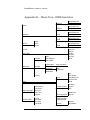
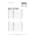
RoadRunner U S E R S G U I D E Appendix B — Rear Panel Pin Outs Relay outputs and opto-inputs: 1 2 14 Relay A, normally open Relay A, normally closed Relay A, common 15 16 3 Relay B, normally open Relay B, normally closed Relay B, common 4 5 17 Relay C, normally open Relay C, normally closed Relay C, common 18 19 6 Relay D, normally open Relay D, normally closed Relay D, common 8 21 10 22 11 23 12 24 OPA+ OPAOPB+ OPBOPC+ OPCOPD+ OPD- 20, 25 Ground 12, 13 +5 VDC Remote Control / Software Upgrade: 2 3 5 TD RD Gnd 74 RoadRunner U S E R S G U I D E Appendix C — ISDN Ordering and Provisioning North American ISDN Ordering Contacts Ameritech AT&T Bell Atlantic Bellcore BellSouth Cincinnati Bell GTE MCI Nevada Bell NYNEX Pacific Bell Rochester Telephone SNET Sprint Stentor Canada Southwestern Bell US West Wiltel 800-TEAMDATA 800-222-7956 800-570-ISDN 800-992-ISDN 800-428-ISDN 800-566-DATA 800-888-8799 800-MCI-ISDN 702-333-4811 800-GET-ISDN 800-4PB-ISDN 716-777-1234 203-553-2369 913-624-4162 800-578-ISDN 800-992-ISDN 800-246-5226 or 303-896-8301 918-588-5069 North American ISDN Provisioning In an effort to make ISDN ordering and provisioning as easy as possible, we recommend faxing the following five pages to your ISDN service provider. If provisioned as shown on these pages, your IDSN circuit will work with your RoadRunner, regardless of terminal adapter used. If given a choice between AT&T Custom or National ISDN, we recommend National ISDN. Also note that when ordering ISDN service, you must ask for long distance service and specify a carrier. Unlike regular telephone service, long distance is not automatically provided. 75 RoadRunner FAX-PAGE 1 U S E R S G U I D E AT&T 5ESS Custom Request from the telephone company an ISDN line in a “Point To Point” configuration with 2B1Q line code. Your ISDN line must be configured to allow circuit switched data on both B-channels and signaling on the Dchannel. Request that the Telephone Company program your ISDN line with the following attributes: n Maximum terminals set to 1 (this tells the switch that there is 1 terminal active on this line.) n Maximum B-channels set to 2; Actual User settings (this tells the switch that you are an actual user and may use both B-channels simultaneously.) n Circuit switched data set to 2; circuit switched data channel set to any (this tells the switch that you may use both B-channels simultaneously. The “Any” tells the switch that either B-channel can be used for data.) n Terminal type is Type A - Basic Terminal (this tells the switch you are a basic ISDN terminal.) n Display set to Yes (this tells the switch that you have display capabilities.) n Call appearance quantity set to 1 (this tells the switch that you want 1 appearance of your primary telephone number.) n Call appearance preference set to Idle (this tells the switch that your software will make a positive choice of which cal appearance it will use to initiate a call.) The Telephone Company will also need to know any additional voice features that you require on your ISDN lines. Examples of these features are Caller ID and Call Forwarding. PLEASE REMEMBER TO SPECIFY A LONG DISTANCE CARRIER. 76 RoadRunner FAX-PAGE 2 U S E R S G U I D E AT&T 5ESS - National ISDN 1 Request from the telephone companies a National ISDN 1 ISDN line in a “multipoint” configuration with 2B1Q line code. The optional “multipoint” configuration will allow you to have a separate telephone number for each B-channel; however, it will physically be only one ISDN line. The Telephone Company should supply you with a different telephone number and SPID (Service Profile Identification) for each Bchannel in a multipoint arrangement. Your ISDN line must be configured to allow circuit switched data on both B-channels and signaling on the Dchannel. Request that the Telephone Company program your ISDN line with the following attributes: n Maximum terminals set to 2 (this tells the switch that there are 2 terminals active on this line.) n Maximum B-channels set to 2; Actual User settings (this tells the switch that you are an actual user and may use both B-channels simultaneously.) n Circuit switched data set to 2; circuit switched data channel set to any (this tells the switch that you may use both B-channels simultaneously. The “Any” tells the switch that either B-channel can be used for data.) n Terminal type is Type A - Basic Terminal (this tells the switch you are a basic ISDN terminal.) n Display set to Yes (this tells the switch that you have display capabilities.) n Circuit switched data limit set to 2 (this tells the switch that you may receive 2 data calls.) n Call appearance preference set to Idle (this tells the switch that your software will make a positive choice of which cal appearance it will use to initiate a call.) The telephone company will also need to know any additional voice features that you require on your ISDN lines. Examples of these features are Caller ID and Call Forwarding. PLEASE REMEMBER TO SPECIFY A LONG DISTANCE CARRIER. 77 RoadRunner FAX-PAGE 3 U S E R S G U I D E AT&T 5ESS — Custom • 2B1Q line code • 2B&D line - Point To Point • B1 - circuit switched voice/data • B2 - circuit switched voice/data • D - signaling only • set MTERM to 1 • set MAXB CHNL to 2; ACT USR to Y • set CSD to 2; CSD CHL to ANY • set TERMTYP to TYPE-A; DISPLAY to Y • set CA QTY to 1 • set CA PREF to I • list any additional data features required • specify long distance carrier AT&T 5ESS — National ISDN • 2B1Q line code • 2B&D line - Standard • B1 - circuit switched voice/data • B2 - circuit switched voice/data • D - signaling only • set MTERM to 2 • set CHNL to 2; ACT USR to Y • set CSD to 2; CSD CHL to ANY • set TERMTYP to TYPE-A; DISPLAY to Y • set CSD limit to 2 • set CA PREF to I • Optional - multipoint; different DN for each B-channel, but same OE (office equipment.) • list any additional data features required • specify long distance carrier 78 RoadRunner FAX-PAGE 4 U S E R S G U I D E Northern Telecomm DMS-100 BC-35 National ISDN 1 Request from the telephone companies a National ISDN 1 ISDN line with 2B1Q line code. Your ISDN line must be configured to allow circuit switched data on both B-channels and signaling on the D-channel. The telephone company should supply you with a separate telephone number and SPID (Service Profile Identification) for each B-channel; however, it will physically be only one ISDN line. Request that the Telephone Company program your ISDN line with the following attributes: B1 and B2 should be set as follows: • Set the circuit switch option to Yes; set the barrier restriction option to no packet mode data (NOPMD) only (this tells the switch that you require circuit switch ability on your B-channel, The bearer restriction on your line means that you are not allowed packet data on your B-channel.) • Set protocol to function version 2; (PVC2) (this tells the switch that your CPE software is using National ISDN 1 protocol.) • Set the service profile identification (SPID) suffix to 1 (this tells the switch that the digit following your telephone number will be 1. The SPID format is area code + 7 digit number + 1 + 00. • Set the Terminal Endpoint Identifier (TEI) to Dynamic (this tells the switch that you can accept any TEI value from 64 to 126.) • Set Ring to Yes (this tells the switch to send an alerting message to your CPE when there is an incoming call.) • Set the maximum keys to 10 (this tells the switch how much memory to allocate for features.) • Set Key system (EKTS) option to No (this tells the switch that you are not a key system.) • Place the lower layer compatibility option for data on the B-channels (this tells the switch that your CPE may utilize the lower layer compatibility information element for data on the B-channels.) • Place calling subaddress option for data on the B-channels (this tells the switch that your CPE will send a subaddress.) • Place called subaddress option for data on the B-channels (this tells the switch that your CPE can receive a subaddress.) The Telephone Company will also need to know any additional data features that you require on your ISDN lines. 79 RoadRunner FAX-PAGE 5 U S E R S G U I D E Northern Telecomm DMS-100 BC-35 National ISDN 1 • 2B1Q line code • 2B&D line • B1 - set circuit switch to YES; set BEARER RESTRICTION to NOPMD (no packet) • • functional version 2; (PVC 2) • set SPID-SUFFIX to 1 • set TEI to DYNAMIC • set RING to YES • set MAXKEYS to 10 • set EKTS to NO • set data option: PROVLLC CMDATA (lower layer compatibility) • set data option: PROVCGS CMDATA (calling subaddress) • set data option: PROVCDS CMDATA (called subaddress) B2 - set circuit switch to YES; set BEARER RESTRICTION to NOPMD (no packet) • functional version 2; (PVC 2) • set SPID-SUFFIX to 1 • set TEI to DYNAMIC • set RING to YES • set MAXKEYS to 10 • set EKTS to NO • set data option: PROVLLC CMDATA (lower layer compatibility) • set data option: PROVCGS CMDATA (calling subaddress) • set data option: PROVCDS CMDATA (called subaddress) List any additional data features required for B1 and B2 80 RoadRunner U S E R S G U I D E Appendix D — Menu Tree – ISDN Operation MPEGL2 Setup Sequence Activate MPEGL3 Setup Sequence Activate G.722 Setup Sequence Activate CCSO Setup Sequence Activate CCSN Setup Sequence Activate Status Operation DIF/TA Setup Save Recall Sys LB Save Crnt View Dir Edit Dir Add Entry Del Entry Del All Speed Dial Encoder Advanced ACE Sine Detector ISO Header Independent setup sequence Audio Out ACE Status Bits Mute Copy/Swap Decoder Dig I/F Type Auto Answer Autp Reconnect Dial Time-Out Redial Virtual Action Print Event Set Timer Stop Timer Program Remote Control Port Baud Protocol Echo L2 Fmt Mux Mode Mux Rate Port Baud Display Contrast Keypad Beeper Hot Key Maint Logic Language Ancillary Data Delete Entry TA Configuration Clear All General 81 Versions Set Defaults Appendix E — Warranty MUSICAM USA, formerly known as Corporate Computer Systems (CCS) warrants to the original purchaser that each of its hardware products and all component s therein contained will be free from defects in materials and/or workmanship for one (1) year from the date of purchase. Any warranty hereunder is extended only to the original purchaser and is not assignable. In the event of a malfunction or other indication of failure attributable directly to faulty workmanship and/or material, MUSICAM USA will, at its option, repair or replace said device or components, to whatever extent it shall deem necessary to restore said device to proper operating condition. Before returning a device for repair, the customer must call MUSICAM USA at (732)739-5600 and obtain a return authorization number. This number should be included with the customer’s mailing address and telephone number when the product is returned. Products must be returned to: MUSICAM USA 670 North Beers St. Building #4 Holmdel, NJ 07733 U.S.A. Attention: Warranty Repair During the first year after the date of purchase, all labor and materials will be provided without charge. There shall be no warranty for either parts or labor after the expiration of 1 year from the date of purchase. Units must be returned postage pre-paid. It is recommended that the unit be insured and securely packed when shipped. Units returned which are out of warranty will be repaired or replaced (at the option of MUSICAM USA) and the customer will be charged for parts and labor at current rates. Units will be returned to the customer after repair or replacement has been completed by carrier and method chosen by MUSICAM USA to any destination within the United States of America. Should a customer desire some other specific form of conveyance, or be located beyond the US borders, then the customer must bear the cost of return shipment. The customer shall be solely responsible for the failure of any MUSICAM USA hardware computer product, or component thereof, resulting from accident, abuse or misapplication of the product, and MUSICAM USA assumes no liability as a consequence of such events under the terms of this Warranty. While every effort on the part of MUSICAM USA has been made to provide clear and accurate technical information on the application of its products, MUSICAM USA assumes no liability in any events which may arise from the use of said technical information. THERE ARE NO OTHER WARRANTIES MUSICAM USA DISCLAIMS ALL OTHER WARRANTIES, EITHER EXPRESS OR IMPLIED, INCLUDING BUT NOT LIMITED TO IMPLIED WARRANTIES OF MERCHANTABILITY AND FITNESS FOR A PARTICULAR PURPOSE. THIS LIMITED WARRANTY GIVES YOU SPECIFIC LEGAL RIGHTS. YOU MAY HAVE OTHERS, WHICH VARY FROM STATE TO STATE. NO LIABILITY FOR CONSEQUENTIAL DAMAGES IN NO EVENT SHALL MUSICAM USA OR ANY OF ITS SUPPLIERS BE LIABLE FOR ANY DAMAGES WHATSOEVER (INCLUDING, WITHOUT LIMITATION, DAMAGES FOR LOSS OF BUSINESS PROFITS, BUSINESS INTERRUPTION, LOSS OF DATA COMMUNICATIONS, LOSS OF BUSINESS INFORMATION, OR OTHER PECUNIARY LOSS) ARISING OUT OF THE USE OF, OR INABILITY TO USE, THIS MUSICAM USA PRODUCT, EVEN IF MUSICAM USA HAS BEEN ADVISED OF THE POSSIBILITY OF SUCH DAMAGES. BECAUSE SOME STATES DO NOT ALLOW THE EXCLUSION OR LIMITATION OF LIABILITY FOR CONSEQUENTIAL OR INCIDENTAL DAMAGES, THE ABOVE LIMITATIONS MAY NOT APPLY TO YOU. Index Algorithm Cascading, 4, 5 CCSN, 31 CCSO, 31 G.722, 5, 30 MPEG Layer 2, 4, 31 MPEG Layer 3, 4, 31 MUSICAM, 4, 31 Audio mixer, 28 Automatic redial, 26 Broadcasting, 5, 36 Commands CAA, 26 CAC, 26 CCC, 23, 24 CCV, 44 CDI, 41 CDS, 39 CFD, 44 CHU, 41 CIB, 21 CIF, 16 CLC, 19, 20 CLD, 20, 23, 25 CLL, 20, 24, 25 CPC, 42 CRB, 42 CRD, 26 CRE, 42 CSA, 20, 25 CSD, 38, 40 CSE, 39 CSI, 19, 23 CSL, 30 CSW, 18, 23, 24 CTD, 28 CTE, 27 CTF, 21, 25 CTO, 26 CTR, 21, 24, 25 DAL, 35 DBR, 35 DCS, 35 DIN, 35 DLI, 35 DMU, 29, 35 DRS, 36 DSP, 35 ECR, 34 EEP, 34 EOR, 34 EPI, 34 EPR, 34 ESD, 34 ESP, 34 HELP, 41 MBX, 44 MVN, 42 VER, 27 Comrex, 35 Decoder, 30 Advanced setup, 34 Algorithm, 35 Bit rate, 35 Independent, 32, 35 Line format, 35 Status bits, 36 Dialing Manual dialing, 40 Speed Dialing, 40 Termination, 41 Digital interface, 3, 6 Installation, 11 RS422, 7, 11 RS449, 11 Selection, 16, 44 Terminal adapter, 6 Terminal adapters, 4 V.35, 7, 12 X.21, 7, 12 Encoder, 30 Advanced setup, 33 Header bits, 34 Quick setup, 32 Sine detector, 34 Status, 32 Factory defaults Reset, 44 Front panel, 3, 7, 8 Indicators, 4 Keypad, 4 Help, 41 Hot keys, 15 Input Balanced, 3 Level, 29 Level select, 28 Line, 3, 7, 9, 28 Microphone, 3, 7, 9, 28 Mixing, 10 Opto-isolator, 10 Remote control, 7, 10, 41 Unbalanced, 28 ISDN Provisioning, 57 Keypad, 4, 15 Alphanumeric, 15 Beeper, 44 Dial, 15 Hot keys, 15, 43 LCD display, 15 Brightness, 44 Status, 33 LED Clip, 4, 29 Cue, 4 Norm, 4, 29 On Line, 4, 14 Power, 4 Loopback, 6, 29 Menu navigation, 15 Music line, 38 NT-1, 7, 13, 17, 22 Output Balanced, 3, 7, 10, 29 Headphone, 3, 7, 10, 29 Local, 3, 7, 10, 29 Mute, 29 Relay, 7, 10, 41 Return, 3, 7, 10, 29 Unbalanced, 3, 7, 10, 29 PKI, 32 Power, 6, 7, 10 Quick Configuration, 36, 40 Add entry, 39 Delete entry, 39 Edit entry, 39 Quick setup, 32 Quick Status, 32 Rear panel, 3, 7, 9 Reboot, 43 Remote control, 10, 14, 41 Scale Factor Protection, 34, 35 Software Upgrade, 4, 42 Version, 42 Speed Dial, 36, 40 Add entry, 39 Delete entry, 39 Edit entry, 39 Telos Zephyr, 35 Terminal adapter, 6 Auto answer, 26 Auto reconnect, 26 Configuration, 16, 27 Configuration memory, 27, 28 Connections, 7 Country selection, 13, 17, 23, 24 EAZ, 20 ID, 18, 19, 23 Interface mode, 21, 25 LEDs, 7 LLC, 20, 23, 25 Local check, 18, 20 MSN, 20, 24 Redial, 26 Reset, 21, 24, 25 SPID, 18, 19, 23 Sub address, 20, 25 Switch type, 18, 22, 24 TA101, 6, 13, 17 TA201, 6, 13, 22, 24 TA301, 7, 13, 22 Time out, 26 Version, 27 Terminal Adapter Inband, 21 Troubleshooting Audio, 45 Connections, 48, 50 Control, 54 Terminal adapter, 51, 53