1
HARDWARE MANUAL [CONNECTION]
GOT-F900 SERIES GRAPHIC OPERATION TERMINAL
Covered models
Screen creation software
F920GOT-K
F920GOT-BBD-K-E
F920GOT-BBD5-K-E
GT Designer2
(SW*D5C-GTD2-E)
F930GOT(-K)
F930GOT-BWD-E
F930GOT-BBD-K-E
GT Designer
(SW*D5C-GOTR-PACKE)
FX-PCS-DU/WIN-E
F940GOT
F940WGOT-TWD-E
F940GOT-SWD-E/-LWD-E
Handy GOT
F940GOT-SBD-H-E/-LBD-H-E
F943GOT-SBD-H-E/-LBD-H-E
F940GOT-SBD-RH-E/-LBD-RH-E
F943GOT-SBD-RH/-E-LBD-RH-E
GOT-F900 SERIES (CONNECTION)
Foreword
• This manual contains text, diagrams and explanations which will guide the reader in the
correct installation and operation of the GOT-F900 SERIES GRAPHIC OPERATION
TERMINAL. It should be read and understood before attempting to install or use the unit.
• Further information can be found in the GOT-F900 Operation Manual, F920GOT-K
Installation Manual, F930GOT Installation Manual, F930GOT-K Installation Manual,
F940GOT Installation Manual, F940WGOT Installation Manual.
• If in doubt at any stage of the installation of GOT-F900 SERIES GRAPHIC OPERATION
TERMINAL always consult a professional electrical engineer who is qualified and trained to
the local and national standards which apply to the installation site.
• If in doubt about the operation or use of GOT-F900 SERIES GRAPHIC OPERATION
TERMINAL please consult the nearest Mitsubisi Electric distributor.
• This manual is subject to change without notice.
GOT-F900 SERIES (CONNECTION)
GOT-F900 SERIES GRAPHIC OPERATION
TERMINAL
HARDWARE MANUAL (CONNECTION)
Manual number : JY992D94801
Manual revision : C
Date
: MARCH 2003
i
GOT-F900 SERIES (CONNECTION)
ii
GOT-F900 SERIES (CONNECTION)
FAX BACK
Mitsubishi has a world wide reputation for its efforts in continually developing and pushing back
the frontiers of industrial automation. What is sometimes overlooked by the user is the care
and attention to detail that is taken with the documentation. However, to continue this process
of improvement, the comments of the Mitsubishi users are always welcomed. This page has
been designed for you, the reader, to fill in your comments and fax them back to us. We look
forward to hearing from you.
Fax numbers:
Your name: ...................................................
Mitsubishi Electric....
.....................................................................
America
(01) 847-478-2253
Your company: .............................................
Australia
(02) 638-7072
.....................................................................
Germany
(0 21 02) 4 86-1 12
Your location:................................................
Spain
(34) 93-589-1579
.....................................................................
United Kingdom
(01707) 278-695
Please tick the box of your choice
What condition did the manual arrive in?
!Good
!Minor damage
Will you be using a folder to store the manual? !Yes
!No
What do you think to the manual presentation?!Tidy
!Unfriendly
Are the explanations understandable?
!Yes
!Not too bad
!Unusable
!Unusable
Which explanation was most difficult to understand: ..................................................................
....................................................................................................................................................
Are there any diagrams which are not clear?
!Yes
!No
If so,which: ..................................................................................................................................
What do you think to the manual layout?
!Good
!Not too bad
!Unhelpful
If there one thing you would like to see improved, what is it? .....................................................
....................................................................................................................................................
....................................................................................................................................................
Could you find the information you required easily using the index and/or the contents, if
possible please identify your experience: ...................................................................................
....................................................................................................................................................
....................................................................................................................................................
....................................................................................................................................................
....................................................................................................................................................
Do you have any comments in general about the Mitsubishi manuals? .....................................
....................................................................................................................................................
....................................................................................................................................................
....................................................................................................................................................
....................................................................................................................................................
Thank you for taking the time to fill out this questionnaire. We hope you found both the product
and this manual easy to use.
iii
GOT-F900 SERIES (CONNECTION)
iv
GOT-F900 SERIES (CONNECTION)
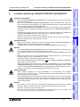
Guidelines for the Safety of the User and Protection of the Graphic operation
terminal GOT-F900
This manual provides information for the use of the Graphic operation terminal GOT-F900. The
manual has been written to be used by trained and competent personnel. The definition of
such a person or persons is as follows;
a) Any engineer who is responsible for the planning, design and construction of automatic
equipment using the product associated with this manual should be of a competent
nature, trained and qualified to the local and national standards required to fulfill that
role. These engineers should be fully aware of all aspects of safety with regards to
automated equipment.
b) Any commissioning or service engineer must be of a competent nature, trained and
qualified to the local and national standards required to fulfill that job. These engineers
should also be trained in the use and maintenance of the completed product. This
includes being completely familiar with all associated documentation for the said product.
All maintenance should be carried out in accordance with established safety practices.
c) All operators of the completed equipment should be trained to use that product in a safe
and coordinated manner in compliance to established safety practices. The operators
should also be familiar with documentation which is connected with the actual operation
of the completed equipment.
Note : Note: the term ‘completed equipment’ refers to a third party constructed device which
contains or uses the product associated with this manual.
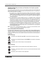
Notes on the Symbols Used in this Manual
At various times through out this manual certain symbols will be used to highlight points of
information which are intended to ensure the users personal safety and protect the integrity of
equipment. Whenever any of the following symbols are encountered its associated note must
be read and understood. Each of the symbols used will now be listed with a brief description of
its meaning.
Hardware Warnings
1) Indicates that the identified danger WILL cause physical and property damage.
2) Indicates that the identified danger could POSSIBLY cause physical and property
damage.
3) Indicates a point of further interest or further explanation.
Software Warnings
4) Indicates special care must be taken when using this element of software.
5) Indicates a special point which the user of the associate software element should
be aware of.
6) Indicates a point of interest or further explanation.
v
GOT-F900 SERIES (CONNECTION)
• Under no circumstances will Mitsubishi Electric be liable responsible for any consequential
damage that may arise as a result of the installation or use of this equipment.
• All examples and diagrams shown in this manual are intended only as an aid to
understanding the text, not to guarantee operation. Mitsubishi Electric will accept no
responsibility for actual use of the product based on these illustrative examples.
• Please contact a Mitsubishi distributor for more information concerning applications in life
critical situations or high reliability.
Note to user
This manual describes the connection procedure to connect the graphic operation terminal
(GOT-F900 Series) to a MELSEC FX/A/QnA/Q Series PLC, PLC by another company, printer,
bar code reader, etc.
Please read this manual before using the GOT-F900 Series, understand sufficiently the use of
the product, then use correctly the product.
For the contents related to the specifications and the operations such as the display function of
the product, refer to the USER’S MANUAL of each product offered separately.
For the details about screen creation for GOT-F900, refer to the OPERATION MANUAL
attached to the screen creation software.
Make sure that this manual is delivered to the end user.
Trademarks and registered trademarks
"Microsoft", "Windows", "Windows 98", "Windows NT", "Windows 2000", "Windows XP",
"Windows Millennium Edition", "MS-DOS", "MS" and "Windows" logos are registered
trademarks of Microsoft Corporation USA in the USA and other countries.
"ESC/P" is a registered trademark of SEIKO EPSON CORPORATION.
"FLEX-PC N Series" is a registered trademark of Fuji Electric Co., Ltd.
"SYSMAC C Series", "CS1 Series", "CJ1 Series" and "SYSMAC α Series" are registered
trademarks of OMRON Corporation.
"SLC500" and "Micro Logix Series" are registered trademarks of Allen-Bradley Co., Inc. in the
USA and other countries.
Each of other company names and product names is a trademark or registered trademark of
each company.
"Windows 98" is used as abbreviation of the Microsoft Windows 98 operating system.
"Windows Millennium Edition" is used as abbreviation of the Microsoft Windows Millennium
Edition operating system.
"Windows NT 4.0" is used as abbreviation of the Microsoft Windows NT 4.0 Workstation
operating system.
"Windows 2000" is used as abbreviation of the Microsoft Windows 2000 operating system.
"Windows XP" is used as abbreviation of the Microsoft Windows XP professional/Home
Edition.
vi
Contents
GOT-F900 SERIES (CONNECTION)
Guidelines .............................................................................................................. v
1. Introduction .....................................................................................................1-1
1.1 Rank and Use Method of This Manual ................................................................ 1-1
1.1.1 Classification of Manuals in Accordance with Purpose ............................................. 1-3
1.2 Abbreviations, Generic Names and Terms Used in This Manual ........................ 1-7
1.2.1
1.2.2
1.2.3
1.2.4
Types and Names of GOT-F900 Series .................................................................... 1-7
Information Offered by Model Name ......................................................................... 1-8
In-built Fonts of Graphic Operation Terminal (Japanese/Overseas product) ............ 1-9
Abbreviation List ...................................................................................................... 1-10
2. Outline.............................................................................................................2-1
2.1 Connection Type Supported by GOT-F900 ......................................................... 2-1
2.1.1 GOT type list and index ............................................................................................. 2-1
2.1.2 Connection type list and index .................................................................................. 2-2
2.2 Outline of Connection Types ............................................................................... 2-3
2.2.1 PLC by Mitsubishi...................................................................................................... 2-3
2.2.2 PLC by Other Companies ......................................................................................... 2-7
2.2.3 Others........................................................................................................................ 2-9
3. Specifications ..................................................................................................3-1
3.1 OS Version and Correspondence to Connected Equipment of GOT-F900 ......... 3-1
3.1.1
3.1.2
3.1.3
3.1.4
How to Confirm OS Version of GOT-F900 ................................................................ 3-1
PLC, Positioning unit, Inverter Manufactured by Mitsubishi ...................................... 3-2
PLC Manufactured by Other Companies .................................................................. 3-4
Others........................................................................................................................ 3-6
3.2 Version of Screen Creation Software and Correspondence to GOT-F900.......... 3-7
3.2.1 How to Conform Version of Screen Creation Software ............................................. 3-8
3.2.2 Screen Creation Software Version Corresponding to GOT-F900 Series ................ 3-10
3.2.3 Screen Creation Software Corresponding to Each Connected Equipment ............. 3-11
3.3 Device Names Which can be Monitored ........................................................... 3-13
3.3.1 Devices in GOT-F900.............................................................................................. 3-13
3.3.2 PLC by Mitsubishi.................................................................................................... 3-14
3.3.3 PLC Units Manufactured by Other Companies ....................................................... 3-20
3.4 Hardware Specifications .................................................................................... 3-28
4. Installation and Wiring of F920GOT-K/F930GOT(-K)/F940(W)GOT ..............4-1
4.1 Outline of Connection .......................................................................................... 4-4
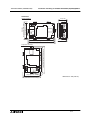
4.2 Name of Each Part .............................................................................................. 4-5
4.2.1 Front Panel ................................................................................................................ 4-5
4.2.2 Rear Panel ................................................................................................................ 4-5
4.2.3 Function of Ports ....................................................................................................... 4-6
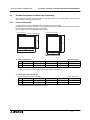
4.3 Outside Dimensions and Panel Face Processing ............................................... 4-8
4.3.1 Panel Cut Dimension................................................................................................. 4-8
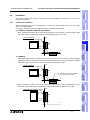
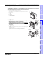
4.4 Installation ........................................................................................................... 4-9
4.4.1 Caution on installation ............................................................................................... 4-9
4.4.2 Inner dimension of the panel required for installation.............................................. 4-10
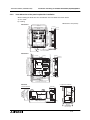
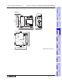
4.4.3 Installation procedure .............................................................................................. 4-13
4.5
4.6
4.7
4.8
Connector Pin Layout and Signal Name (Excluding the 5 V type F920GOT-K.)4-14
Outline of Internal Wiring ................................................................................... 4-15
Wiring for 24V DC and 5V DC Power Supply and Class D Grounding.............. 4-16
Handling of Function Keys (F1 to F8) (F920GOT-K and F930GOT-K) ............. 4-19
4.8.1
4.8.2
4.8.3
4.8.4
Use of function keys ................................................................................................ 4-20
Preparation of Function Key Name Sheet (Available in the F930GOT-K)............... 4-21
Cautions on use ...................................................................................................... 4-22
Label pattern (F930GOT-K) .................................................................................... 4-23
4.9 Setting of Connected Equipment for GOT ......................................................... 4-24
vii
Contents
GOT-F900 SERIES (CONNECTION)
5. Installation and Wiring of Handy GOT ............................................................5-1
5.1 Outline of Connection .......................................................................................... 5-5
5.1.1 Handy GOT (Excluding RH model) ........................................................................... 5-5
5.1.2 Handy GOT (RH model) ............................................................................................ 5-7
5.2 Name of Each Part .............................................................................................. 5-8
5.2.1 Front Panel ................................................................................................................ 5-8
5.2.2 Rear Panel and Connectors ...................................................................................... 5-9
5.3 Outside Dimensions and Installation ................................................................. 5-10
5.3.1 Outside Dimensions ................................................................................................ 5-10
5.3.2 Installation ............................................................................................................... 5-12
5.4 Selection and Installation of External Cable ...................................................... 5-14
5.4.1 Handy GOT (Excluding RH model) ......................................................................... 5-14
5.4.2 Wiring between Handy GOT (RH model) operation switches and connected
equipment................................................................................................................ 5-16
5.4.3 Installation of External Cable................................................................................... 5-18
5.5 Processing Panel Face of Control Box or Cabinet ............................................ 5-20
5.5.1
5.5.2
5.5.3
5.5.4
Selection of relay cable ........................................................................................... 5-20
Appearance shape of Relay Cable.......................................................................... 5-22
Panel Cut Dimension for Relay Cable ..................................................................... 5-28
Panel Cut Dimension for F9GT-HCNB .................................................................... 5-28
5.6 Pin Layout and Signal Allocation of Connector for Serial Communication and
Operation Switches ........................................................................................... 5-29
5.6.1 F9GT-HCABo-oM/F9GT-HCAB1-oM External Cable.............................................. 5-29
5.6.2 F9GT-RHCAB-oM External Cable........................................................................... 5-30
5.7 Outline of Internal Wiring ................................................................................... 5-31
5.8 Wiring for 24V DC Power Supply and Class D Grounding ................................ 5-33
5.9 Wiring and Handling of Operation Switches SW1 to SW4................................. 5-34
5.9.1 Handling of operation switches ............................................................................... 5-34
5.9.2 Preparation of Operation Switch Name Sheet ........................................................ 5-36
5.10 Wiring and Handling of Emergency Stop Switch (ES1) ..................................... 5-38
5.11 Handling of grip switch (excluding RH model) ................................................... 5-40
5.11.1
5.11.2
5.11.3
5.11.4
Function of Grip Switch ........................................................................................... 5-40
Setting in main unit and screen creation software................................................... 5-40
Grip switch operation specifications ........................................................................ 5-41
Communication with connected equipment (grip switch ON/OFF signal) ............... 5-44
5.12 Handling of grip switch (RH model only) ........................................................... 5-46
5.12.1 Wiring of Grip Switch ............................................................................................... 5-46
5.12.2 Setting of Grip Switch LED ...................................................................................... 5-47
5.12.3 LED Action .............................................................................................................. 5-47
5.13
5.14
5.15
5.16
Handling of Keylock Switch (RH model only) .................................................... 5-48
Setting of Connected Equipment for GOT ......................................................... 5-49
Connection Diagram of Handy GOT Operation Switches and Power Supply ... 5-55
Connector Conversion Box F9GT-HCNB .......................................................... 5-57
5.16.1
5.16.2
5.16.3
5.16.4
Outline of Product.................................................................................................... 5-57
Name of Each Part .................................................................................................. 5-57
Specifications .......................................................................................................... 5-58
Installation ............................................................................................................... 5-59
5.17 F9GT-HCNB Conversion Box............................................................................ 5-61
5.18 Diagnostic .......................................................................................................... 5-62
5.18.1 F940GOT Handy (F94*GOT-*BD-H-E) ................................................................... 5-62
5.18.2 F940GOT Handy (F94*GOT-*BD-RH-E)................................................................. 5-63
5.19 How to Read Manual for Handy GOT RH Model............................................... 5-64
viii
Contents
GOT-F900 SERIES (CONNECTION)
6. Connection of Peripheral Equipment
(Screen data transfer/Sequence program transfer and monitor) ....................6-1
6.1 Outline of Connection .......................................................................................... 6-1
6.2 Connection to Personal Computer ...................................................................... 6-3
6.2.1 Screen Data Transfer ................................................................................................ 6-3
6.2.2 Sequence Program Transfer (two-port interface function built)................................. 6-4
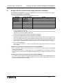
6.2.3 Cable Connection Procedure .................................................................................... 6-5
6.3 Connection of F943 Handy GOT (for PLC) and Personal Computer................... 6-7
6.3.1 Outline ....................................................................................................................... 6-7
6.3.2 Configuration to transfer screen data using PLC connector...................................... 6-7
6.3.3 Changeover of Connection between PLC and Personal Computer .......................... 6-8
6.4 Caution on Use of Peripheral Equipment ............................................................ 6-9
6.4.1 Caution when connecting the GOT and PLC via RS-232C port
(Only in case of the F920GOT-K, F930GOT, F930GOT-K, or F940GOT) ......................... 6-9
6.4.2 Caution when transferring screen data to the F920GOT-K (5V type) ..................... 6-10
6.5 Cable Diagram................................................................................................... 6-12
6.5.1 Cable for Personal Computer .................................................................................. 6-12
6.6 Troubleshooting ................................................................................................. 6-13
7. Connection of Two or More GOT Units...........................................................7-1
7.1 System Condition ................................................................................................ 7-1
7.2 Connection Configuration for Two or More GOT Units........................................ 7-2
7.2.1 Configuration When First GOT Unit is Connected through RS-422 .......................... 7-2
7.2.2 When First GOT Unit is Connected through RS-232C .............................................. 7-4
7.2.3 When Connection is Changed from RS-422 to RS-232C.......................................... 7-5
7.3 Rules in Configuration ......................................................................................... 7-6
7.3.1 Connection Method ................................................................................................... 7-6
7.3.2 Communication Port Number Table .......................................................................... 7-7
7.3.3 Connection Concept in Each Model Name ............................................................... 7-7
7.4 Connection of Four or More Display Units........................................................... 7-8
7.5 Cautions on Connecting Two or More GOT Units ............................................. 7-10
7.5.1 Power ON Sequence............................................................................................... 7-10
7.5.2 Transfer of sequence program and use of monitor ................................................. 7-11
7.6 Setting of Connected Equipment for GOT ......................................................... 7-12
7.6.1 Connection Type (RS-422/RS-232C setting) .......................................................... 7-12
7.6.2 Station Number Setting ........................................................................................... 7-12
7.6.3 Setting Procedure.................................................................................................... 7-13
7.7 Cable Diagram................................................................................................... 7-20
7.8 Troubleshooting ................................................................................................. 7-24
8. Connection of MELSEC-F FX Series PLC ......................................................8-1
8.1 System Condition ................................................................................................ 8-1
8.2 System Configuration .......................................................................................... 8-2
8.2.1 Configuration for CPU Direct Connection (RS-422) .................................................. 8-2
8.2.2 Configuration for CPU Direct Connection (RS-232C)................................................ 8-4
8.3 Cautions on Use of MELSEC-F FX Series .......................................................... 8-6
8.3.1
8.3.2
8.3.3
8.3.4
Device specification................................................................................................... 8-6
Devices which can be monitored............................................................................... 8-6
When GOT-F900 is connected to optional port ......................................................... 8-6
Restrictions in connecting two or more F920GOT-K (5V type) units to FX Series
PLC ........................................................................................................................... 8-9
8.4 Setting of Connected Equipment for GOT ......................................................... 8-10
8.5 Cable Diagram................................................................................................... 8-17
8.6 Troubleshooting ................................................................................................. 8-21
ix
Contents
GOT-F900 SERIES (CONNECTION)
9. Connection of MELSEC-A Series PLC ...........................................................9-1
9.1 System Condition ................................................................................................ 9-2
9.2 System Configuration .......................................................................................... 9-2
9.2.1 Configuration for Direct Connection (RS-422)........................................................... 9-3
9.2.2 Configuration for A Computer Link Connection (RS-422) ......................................... 9-5
9.2.3 Configuration for A Computer Link Connection (RS-232C)....................................... 9-7
9.3 Setting in A Computer Link Connection............................................................... 9-8
9.3.1
9.3.2
9.3.3
9.3.4
9.3.5
Communication Setting Specifications ...................................................................... 9-8
Setting of CD Signal Control (only in RS-232C connection)...................................... 9-9
Setting Examples .................................................................................................... 9-10
Used Connectors and Connector Covers................................................................ 9-13
Cable Specifications and Length ............................................................................. 9-13
9.4 Caution on Use of MELSEC-A Series PLC ....................................................... 9-14
9.4.1 Caution when the GOT-F900 is connected to the computer link unit ...................... 9-14
9.4.2 Caution when displaying the Ascii code .................................................................. 9-14
9.5 Setting of Connected Equipment for GOT ......................................................... 9-15
9.6 Cable Diagram................................................................................................... 9-22
9.7 Troubleshooting ................................................................................................. 9-25
10.Connection of MELSEC-QnA Series PLC....................................................10-1
10.1 System Condition .............................................................................................. 10-2
10.1.1 Restriction When Computer Link Unit for A Series is Used..................................... 10-2
10.2 System Configuration ........................................................................................ 10-3
10.2.1 Configuration for Direct Connection (RS-422)......................................................... 10-3
10.2.2 Configuration for QnA Computer Link Connection (RS-422)................................... 10-5
10.2.3 Configuration for QnA Computer Link Connection (RS-232C) ................................ 10-7
10.3 Setting in QnA Computer Link Connection ........................................................ 10-9
10.3.1 Communication Setting Specifications .................................................................... 10-9
10.3.2 Setting Examples .................................................................................................. 10-10
10.4 Caution on Use of MELSEC-QnA Series PLC ................................................ 10-12
10.4.1 Caution when the GOT is connected to the serial communication unit ................. 10-12
10.4.2 Caution when the GOT is connected to the computer link for the A Series PLC .. 10-12
10.5 Setting of Connected Equipment for GOT ....................................................... 10-13
10.6 Cable Diagram................................................................................................. 10-22
10.7 Troubleshooting ............................................................................................... 10-26
11.Connection of MELSEC-Q Series PLC ........................................................11-1
11.1 System Condition .............................................................................................. 11-2
11.2 System Configuration ........................................................................................ 11-3
11.2.1 Configuration for Direct Connection (RS-232C) ...................................................... 11-3
11.2.2 Configuration for Q Computer Link Connection (RS-422) ....................................... 11-5
11.2.3 Configuration for Q Computer Link Connection (RS-232C) .................................... 11-7
11.3 Setting in Q Serial Communication Unit ............................................................ 11-9
11.3.1 Communication Setting Specifications .................................................................... 11-9
11.3.2 Setting by GPPW .................................................................................................. 11-10
11.3.3 Used Connectors and Connector Covers.............................................................. 11-11
11.4 Setting in Q Multi PLC System (Function version -B or later).......................... 11-12
11.4.1 Direct connection to QCPU ................................................................................... 11-12
11.4.2 Connection to serial communication ..................................................................... 11-13
11.5 Caution on Use of MELSEC-Q Series PLC ..................................................... 11-14
11.5.1
11.5.2
11.5.3
11.5.4
Restriction in device specification ......................................................................... 11-14
Caution when the GOT is connected to the serial communication unit ................. 11-14
Caution when connecting to Q multiple CPU system ............................................ 11-14
Caution when setting screen creation software..................................................... 11-15
11.6 Setting of Connected Equipment for GOT ....................................................... 11-16
11.7 Cable Diagram................................................................................................. 11-24
11.8 Troubleshooting ............................................................................................... 11-28
x
Contents
GOT-F900 SERIES (CONNECTION)
12.Connection of FX Series Positioning Unit (FX(2N)-10/20GM).......................12-1
12.1 System Condition .............................................................................................. 12-1
12.2 System Configuration ........................................................................................ 12-2
12.2.1 Configuration for GMCPU direct connection (RS-422)............................................ 12-2
12.3 Cautions on use of FX Series positioning unit ................................................... 12-4
12.3.1 Device specification................................................................................................. 12-4
12.3.2 Devices which can be monitored............................................................................. 12-4
12.3.3 Caution on connection of a programming tool to the FX Series positioning unit ..... 12-4
12.4 Setting of Connected Equipment for GOT ......................................................... 12-5
12.5 Cable Diagram................................................................................................. 12-11
12.6 Troubleshooting ............................................................................................... 12-13
13.Connection of FREQROL (S500/E500/A500) Inverter .................................13-1
13.1 System Condition .............................................................................................. 13-2
13.2 System Configuration ........................................................................................ 13-2
13.2.1 Configuration for CPU Direct Connection (RS-422) ................................................ 13-2
13.3 Setting in FREQROL Inverter ............................................................................ 13-6
13.3.1
13.3.2
13.3.3
13.3.4
Communication Setting Specifications .................................................................... 13-6
Setting Examples .................................................................................................... 13-7
Inverter Connector Specifications ........................................................................... 13-9
Specification of Station Number in Creating Screen ............................................. 13-10
13.4 Cautions on Use of FREQROL Series Inverter ............................................... 13-11
13.4.1
13.4.2
13.4.3
13.4.4
13.4.5
13.4.6
13.4.7
Device specification............................................................................................... 13-11
Changeover from the GOT (communication) to the PU operation mode .............. 13-11
When "8888" or "9999" is set to a parameter (Pr) of the inverter .......................... 13-11
Specification of the program operation (PG) devices ............................................ 13-12
Caution on setting of the calibration parameters (Pr900 to Pr905) ....................... 13-12
Restriction in simultaneous specification of PG and Pr devices on one screen .... 13-12
Caution on connecting to the PU port (only in the E500 and the A500) ................ 13-12
13.5 Correspondence Between Devices of GOT and Parameters .......................... 13-13
13.6 FREQROL Inverter Parameter List.................................................................. 13-18
13.6.1 Parameters ............................................................................................................ 13-18
13.6.2 Communication Parameters .................................................................................. 13-25
13.7 Setting of Connected Equipment for GOT ....................................................... 13-26
13.8 Cable Diagram................................................................................................. 13-32
13.9 Troubleshooting ............................................................................................... 13-35
14.Connection of Microcomputer ......................................................................14-1
14.1 System Condition .............................................................................................. 14-2
14.2 System Configuration ........................................................................................ 14-3
14.2.1 Configuration for CPU Direct Connection (RS-422) ................................................ 14-3
14.2.2 Configuration for CPU Direct Connection (RS-232C).............................................. 14-5
14.3 Outline of Communication and Specifications ................................................... 14-6
14.3.1 Outline of Communication ....................................................................................... 14-6
14.3.2 Communication Setting Specifications .................................................................... 14-7
14.4 Memory Map...................................................................................................... 14-7
14.4.1 Data Area ................................................................................................................ 14-7
14.4.2 Special Memory Data List ..................................................................................... 14-10
14.4.3 Error Code List ...................................................................................................... 14-12
14.5 Communication Command .............................................................................. 14-13
14.5.1
14.5.2
14.5.3
14.5.4
14.5.5
14.5.6
14.5.7
Outline of Communication Procedure ................................................................... 14-13
Command List and Compatible Version of GOT-F900.......................................... 14-14
Data Transfer Format (protocol) ............................................................................ 14-15
Character Code List .............................................................................................. 14-15
Station Number Setting ......................................................................................... 14-16
Sum Check Code .................................................................................................. 14-16
Interrupt Code List ................................................................................................. 14-17
xi
Contents
GOT-F900 SERIES (CONNECTION)
14.6 Command Details ............................................................................................ 14-18
14.6.1
14.6.2
14.6.3
14.6.4
14.6.5
Batch Read Command .......................................................................................... 14-18
Batch Write Command .......................................................................................... 14-19
Bit-oriented Write Command ................................................................................. 14-20
Fill Command ........................................................................................................ 14-22
Interrupt Code ....................................................................................................... 14-22
14.7 Caution on Use of Microcomputer Connection ................................................ 14-23
14.7.1 When Using F920GOT-K ...................................................................................... 14-23
14.8 Setting of Connected Equipment for GOT ....................................................... 14-24
14.9 Cable Diagram................................................................................................. 14-31
14.10Troubleshooting .............................................................................................. 14-33
14.11BASIC Program Example ............................................................................... 14-35
15.Connection of SYSMAC C Series PLC (Manufactured by Omron) ..............15-1
15.1 System Condition .............................................................................................. 15-2
15.1.1 Classification of Host Link/Serial Communication Units .......................................... 15-3
15.2 System Configuration ........................................................................................ 15-4
15.2.1 Configuration for SYSMAC C Host Link Connection (RS-422) ............................... 15-4
15.2.2 Configuration for SYSMAC C Host Link Connection (RS-232C)............................. 15-6
15.3
15.4
15.5
15.6
15.7
Communication Specifications for Host Link ..................................................... 15-8
Setting Examples in CQM1/CQM1H/C200H Series .......................................... 15-9
Setting Examples in CS1/CJ1 Series .............................................................. 15-12
Setting Examples in SYSMAC α(C200HE/HG/HX)/CPM 1A/2A/2C Series .... 15-14
Caution on Use of SYSMAC C Series PLC ..................................................... 15-17
15.7.1 Modes in the SYSMAC C Series PLC ................................................................... 15-17
15.7.2 Forced ON/OFF on the device monitor screen of the GOT-F900 ......................... 15-17
15.7.3 Restriction in functions .......................................................................................... 15-17
15.8 Setting of Connected Equipment for GOT ....................................................... 15-18
15.9 Cable Diagram................................................................................................. 15-24
15.10Troubleshooting .............................................................................................. 15-28
16.Connection of FLEX-PC N Series PLC (Manufactured by Fuji Electric) ......16-1
16.1 System Condition .............................................................................................. 16-1
16.2 System Configuration ........................................................................................ 16-2
16.2.1 Configuration for Link Unit Connection (RS-422) .................................................... 16-2
16.2.2 Configuration for Link Unit Connection (RS-232C).................................................. 16-3
16.3 Setting in Link Unit............................................................................................. 16-4
16.3.1 Communication Setting Specifications .................................................................... 16-4
16.3.2 Setting Examples .................................................................................................... 16-5
16.4 Caution on Use of FLEX-PC N Series PLC ....................................................... 16-6
16.4.1 Devices which can be monitored............................................................................. 16-6
16.5 Setting of Connected Equipment for GOT ......................................................... 16-7
16.6 Cable Diagram................................................................................................. 16-12
16.7 Troubleshooting ............................................................................................... 16-15
17.Connection of Machine Controller CP9200SH
(PLC Manufactured by Yaskawa Electric) ....................................................17-1
17.1 System Condition .............................................................................................. 17-1
17.2 System Configuration ........................................................................................ 17-2
17.2.1 Configuration for CPU Direct Connection (RS-422) ................................................ 17-2
17.2.2 Configuration for CPU Direct Connection (RS-232C).............................................. 17-4
17.3 Setting in Machine Controller ............................................................................ 17-6
17.3.1 Communication Setting Specifications .................................................................... 17-6
17.4 Setting of Connected Equipment for GOT ......................................................... 17-7
17.5 Cable Diagram................................................................................................. 17-12
17.6 Troubleshooting ............................................................................................... 17-15
xii
Contents
GOT-F900 SERIES (CONNECTION)
18.Connection of FP Series PLC (Manufactured by Matsushita Electric Works)18-1
18.1 System Condition .............................................................................................. 18-2
18.1.1 Classification of Product Names ............................................................................. 18-2
18.2 System Configuration ........................................................................................ 18-3
18.2.1 Configuration for CPU Direct Connection (RS-232C).............................................. 18-3
18.3 Setting of Series ................................................................................................ 18-5
18.3.1 Communication Setting Specifications .................................................................... 18-5
18.3.2 Setting Examples in Computer Communication Unit............................................... 18-6
18.4 Cautions on Use of FP Series ........................................................................... 18-7
18.4.1 Device specification................................................................................................. 18-7
18.4.2 Devices which can be monitored............................................................................. 18-7
18.4.3 Cautions on connection of the control unit, the CPU unit and the computer
communication unit ................................................................................................. 18-7
18.5 Setting of Connected Equipment for GOT ......................................................... 18-8
18.6 Cable Diagram................................................................................................. 18-14
18.7 Troubleshooting ............................................................................................... 18-19
19.Connection of SLC500/MicroLogix Series PLC
(Manufactured by Allen-Bradley) ..................................................................19-1
19.1 System Condition .............................................................................................. 19-2
19.2 System Configuration ........................................................................................ 19-3
19.2.1 Configuration for CPU Direct Connection (RS-232C).............................................. 19-3
19.3 Setting in SLC500.............................................................................................. 19-5
19.3.1 Communication Setting Specifications .................................................................... 19-5
19.3.2 GOT-F900 Transmission Specifications.................................................................. 19-5
19.4 Setting in MicroLogix ......................................................................................... 19-6
19.4.1 Communication Setting Specifications .................................................................... 19-6
19.4.2 GOT-F900 Transmission Specifications.................................................................. 19-6
19.5 Device Specification Method ............................................................................. 19-7
19.5.1 Device Format ......................................................................................................... 19-7
19.5.2 File Number and Element Range ............................................................................ 19-9
19.5.3 Restriction in Device Specification .......................................................................... 19-9
19.6 Caution on Use of SLC500/MicroLogix Series PLC ........................................ 19-10
19.6.1 Device setting in advance ..................................................................................... 19-10
19.6.2 Caution on use of the sampling function ............................................................... 19-10
19.7 Setting of Connected Equipment for GOT ....................................................... 19-11
19.8 Cable Diagram................................................................................................. 19-17
19.9 Troubleshooting ............................................................................................... 19-19
20.Connection of SIMATIC S7-200/300/400 Series PLC
(Manufactured by Siemens AG)....................................................................20-1
20.1 System Condition .............................................................................................. 20-2
20.2 System Configuration ........................................................................................ 20-3
20.2.1 Configuration for CPU Direct Connection (RS-232C).............................................. 20-3
20.2.2 Introduction of Options Manufactured by Siemens AG ........................................... 20-5
20.3 Setting in SIMATIC S7-200 ............................................................................... 20-6
20.3.1 Communication Setting Specifications .................................................................... 20-6
20.3.2 GOT-F900 Transmission Specifications.................................................................. 20-8
20.4 Setting in SIMATIC S7-300/400 ........................................................................ 20-8
20.4.1 Communication Setting Specifications .................................................................... 20-8
20.4.2 GOT-F900 Transmission Specifications.................................................................. 20-8
20.5 Device Specification Method ............................................................................. 20-9
20.5.1 Device Format in SIMATIC S7-200 ......................................................................... 20-9
20.5.2 Device Format in SIMATIC S7-300/400 ................................................................ 20-10
20.5.3 Supplementary Items ............................................................................................ 20-11
xiii
Contents
GOT-F900 SERIES (CONNECTION)
20.6 Caution on Use of SIMATIC S7-200/300/400 Series PLC .............................. 20-11
20.6.1 Restriction in devices depending on the model ..................................................... 20-11
20.6.2 Restriction in device specification ......................................................................... 20-11
20.7 Setting of Connected Equipment for GOT ....................................................... 20-12
20.8 Cable Diagram................................................................................................. 20-19
20.9 Troubleshooting ............................................................................................... 20-21
21.Connection of Printer....................................................................................21-1
21.1 System Condition .............................................................................................. 21-1
21.2 System Configuration ........................................................................................ 21-2
21.2.1 Configuration for Printer Connection ....................................................................... 21-2
21.2.2 Applicable port on GOT-F900 ................................................................................. 21-2
21.3 Printer Communication Setting .......................................................................... 21-2
21.3.1 Transmission Specifications and Communication Format....................................... 21-2
21.4 Cautions on Use of Printer ................................................................................ 21-4
21.4.1 Caution on printer setting ........................................................................................ 21-4
21.4.2 Concurrent use of microcomputer and printer ......................................................... 21-4
21.5 Setting of Connected Equipment for GOT ......................................................... 21-5
21.6 Cable Diagram................................................................................................... 21-7
22.Connection of Bar Code Reader ..................................................................22-1
22.1 System Condition .............................................................................................. 22-2
22.2 Connection Configuration .................................................................................. 22-2
22.2.1 Configuration for Bar Code Reader Connection ..................................................... 22-2
22.3 Bar Code Reader Communication Setting ........................................................ 22-3
22.3.1
22.3.2
22.3.3
22.3.4
Transmission Specifications and Communication Format....................................... 22-3
Bar Code Reader Control Devices .......................................................................... 22-4
Bar Code Data Setting ............................................................................................ 22-6
Sequence Program Example .................................................................................. 22-7
22.4 Caution on Use of Bar Code Reader ................................................................. 22-8
22.4.1 Caution on bar code reader setting ......................................................................... 22-8
22.5 Setting of Connected Equipment for GOT ......................................................... 22-9
22.6 Cable Diagram................................................................................................. 22-12
22.7 Troubleshooting ............................................................................................... 22-12
23.Appendix ......................................................................................................23-1
23.1 Backlight ON/OFF Status Control Method and Replacement Procedure .......... 23-2
23.1.1
23.1.2
23.1.3
23.1.4
Backlight Control Operation .................................................................................... 23-2
Assigning Device to Control ON/OFF Status of the Backlight ................................. 23-3
Backlight Replacement Procedure .......................................................................... 23-5
Cautions on Use of Backlight .................................................................................. 23-6
23.2 Battery Voltage Drop Detection Method and Replacement Procedure ............. 23-7
23.2.1 RAM Data When Battery Voltage Drops ................................................................. 23-7
23.2.2 Assigning Device to Check Battery Voltage Drop ................................................... 23-8
23.2.3 Battery Replacement Procedure ........................................................................... 23-10
23.3 Connection of Programming Tools via FX-2PIF .............................................. 23-12
23.3.1
23.3.2
23.3.3
23.3.4
23.3.5
How to Monitor Using A6GPP/A7PHP/HPP .......................................................... 23-12
Restrictions in Number of Devices Monitored When Using FX-2PIF .................... 23-14
Switch Setting in FX-2PIF ..................................................................................... 23-16
Cautions on Use of FX-2PIF ................................................................................. 23-17
Cable Diagram ...................................................................................................... 23-18
23.4 GOT-F900 Connector Signal Correspondence Table
(Excluding the 5V type F920GOT-K.) .............................................................. 23-19
23.4.1 RS-422 Correspondence Table ............................................................................ 23-19
23.4.2 RS-232C Correspondence Table ......................................................................... 23-19
23.5 Error Messages in GOT-F900 Series .............................................................. 23-20
23.5.1 Error Messages During Screen Operation ............................................................ 23-22
xiv
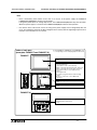
Introduction 1
GOT-F900 SERIES (CONNECTION)
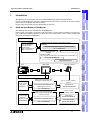
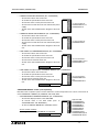
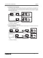
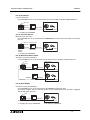
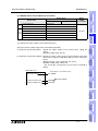
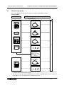
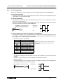
Introduction
Hardware manual (separate manual) [this manual]
Handling of GOT and how to connect and set connected
equipment
Connected equipment
- PLC by Mitsubishi
- PLC by another
manufacturer
- Microcomputer board
- Bar code reader
GOT-F900 HARDWARE MANUAL [CONNECTION]
(No.:JY992D94801)
Manual packed together
with GOT
Handling of GOT
(The contents described here are included in the manual above.)
INSTALLATION MANUAL
or
HARDWARE MANUAL
Specifications
Hardware
3
4
installation
and Wiring of
F940GOT
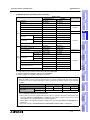
The following manuals are offered for the GOT-F900 Series.
Each manual is classified in accordance with the purpose. Read a manual suitable to your purpose,
then understand handling, operations and function of the GOT and the screen creation software GT
Designer2, GT Designer and DU/WIN.
5
installation
and Wiring of
Handy GOT
Rank and Use Method of This Manual
PLC
GOT-F900
Personal computer
Connection of
Peripheral
Equipment
6
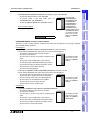
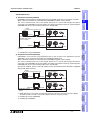
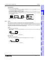
GOT operation manual for GT
Designer2 (separate manual)
Screen creation
using GT
Designer2
GOT-F900 OPERATION MANUAL
[GT Designer2 version]
Screen creation software
manual
GT Designer2
OPERATING MANUAL
(No.:JY997D09101)
GOT operation manual for GT
Designer and FX-PCS-DU/WIN-E
(separate manual)
Screen creation
using GT
Designer or FXPCS-DU/WIN-E
Screen creation
software manual
GT Designer
OPERATING MANUAL
GOT-F900 OPERATION MANUAL
(No.:JY992D94701)
FX-PCS-DU/WIN-E
OPERATION MANUAL
1-1
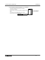
8
Connection of
MELSEC-F
FX Series PLC
Operation/software
Connection of
Two or More
GOT Units
7
9
Connection of
MELSEC-A
Series PLC
1.1
2
Outline
We appreciate it very much that you have purchased Mitsubishi graphic operation terminal.
Please read thoroughly this manual to understand sufficiently and use correctly the functions and the
performance of the graphic operations terminal.
Please make sure that this manual is delivered to the end user.
10
Connection of
MELSEC-QnA
Series PLC
1.
Introduction
1
GOT-F900 SERIES (CONNECTION)
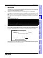
Introduction 1
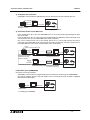
This manual describes how to set the screen creation software, select cables and perform wiring in
connecting the GOT-F900 Series to a connected equipment.
Information Offered by Model name and In-built Fonts ............................................................Introduction
Outline of Connection Types ....................................................................................................... Section 1
Applicable PLC and connection type .......................................................................................... Section 2
Screen Creation Software Version
Device Names Which can be Monitored
↓
This manual can be classified as follows in accordance with the type of GOT-F900 Series.
F920GOT-K, F930GOT(-K), F940GOT or F940WGOT Series..................................Read from Section 3.
Handy GOT Series....................................................................................................Read from Section 4.
1-2
GOT-F900 SERIES (CONNECTION)
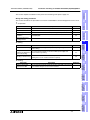
Introduction 1
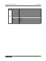
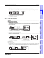
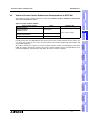
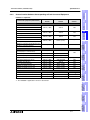
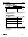
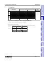
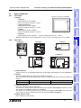
Classification of Manuals in Accordance with Purpose
When requiring a manual not included with the product, contact our sales representative.
2
COMMON HARDWARE MANUAL (sent separately)
MODEL CODE
09R805
IIt is included as PDF
data on CD-ROM of
screen creation software
SW"D5C-GTD2-E.
It is included as PDF
data on CD-ROM of
screen creation software
SW"D5C-GOTR-PACK.
HARDWARE MANUAL AND INSTALLATION MANUAL
Describes mainly the outside dimension, the installation, the power supply wiring and the electrical
specifications.
F920GOT-BBD5-K-E, F920GOT-BBD-K-E INSTALLATION MANUAL (No. JY997D02201)
F930GOT INSTALLATION MANUAL (No. JY992D95701)
-
•
To learn the features of the main unit.
To confirm the specifications of the main unit.
To learn the name of each part of the main unit.
To learn how to install the main unit and wire the power
supply.
To look at the external dimensions diagram of the main
unit.
INSTALLATION
MANUAL
-
7
It is included with the
F93"GOT-BWD-E.
8
F930GOT-BBD-K-E INSTALLATION MANUAL (No. JY997D02501)
-
To learn the features of the main unit.
To confirm the specifications of the main unit.
To learn the name of each part of the main unit.
To learn how to install the main unit and wire the power
supply.
To look at the external dimensions diagram of the main
unit.
INSTALLATION
MANUAL
-
6
Connection of
MELSEC-F
FX Series PLC
•
It is included with the
F920GOT-BBD-K-E and
F920GOT-BBD5-K-E.
5
Connection of
Peripheral
Equipment
-
To learn the features of the main unit.
To confirm the specifications of the main unit.
To learn the name of each part of the main unit.
To learn how to install the main unit and wire the power
supply.
To look at the external dimensions diagram of the main
unit.
INSTALLATION
MANUAL
-
4
It is included with the
F930GOT-BBD-K-E.
9
Connection of
MELSEC-A
Series PLC
•
3
Specifications
-
HARDWARE
MANUAL
-
To learn how to connect the GOT to a personal
computer (for screen data transfer).
To understand how to connect the main unit to
equipment.
To learn how to set the screen creation software.
installation
and Wiring of
F940GOT
-
installation
and Wiring of
Handy GOT
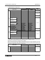
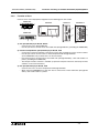
GOT-F900 SERIES GRAPHIC OPERATION TERMINAL HARDWARE MANUAL [CONNECTION]
(No. JY992D94801)
Connection of
Two or More
GOT Units
•
Outline
Corresponds to all of the F920GOT-K, F930GOT(-K), F940GOT and handy GOT Series, and describes
in details the connection to a PLC or personal computer and the setting method.
10
1-3
Connection of
MELSEC-QnA
Series PLC
1.1.1
Introduction
1
GOT-F900 SERIES (CONNECTION)
•
F940GOT INSTALLATION MANUAL (No. JY992D94201)
-
To learn the features of the main unit.
To confirm the specifications of the main unit.
To learn the name of each part of the main unit.
To learn how to install the main unit and wire the power
supply.
To look at the external dimensions diagram of the main
unit.
INSTALLATION
MANUAL
-
It is included with the
F940WGOT-TWD-E.
F940 HANDY GOT HARDWARE MANUAL (No. JY992D86901)
To learn the features of the main unit.
To confirm the specifications of the main unit.
To learn the name of each part of the main unit.
To learn how to install the main unit.
To look at the external dimensions diagram of the main
unit.
MODEL CODE
HARDWARE
MANUAL
-
•
It is included with the
F94"GOT-SWD-E and
F94"GOT-LWD-E.
F940WGOT INSTALLATION MANUAL (No. JY992D93901)
-
•
To learn the features of the main unit.
To confirm the specifications of the main unit.
To learn the name of each part of the main unit.
To learn how to install the main unit and wire the power
supply.
To look at the external dimensions diagram of the main
unit.
INSTALLATION
MANUAL
-
•
Introduction 1
It is included with the
F94"GOT-SBD-H-E and
F94"GOT-LBD-H-E.
09R810
F940 HANDY GOT (RH model) HARDWARE MANUAL (No. JY992D99901)
To learn the features of the main unit.
To confirm the specifications of the main unit.
To learn the name of each part of the main unit.
To learn how to install the main unit.
To look at the external dimensions diagram of the main
unit.
MODEL CODE
HARDWARE
MANUAL
-
It is included with the
F94"GOT-SBD-RH-E
and
F94"GOT-LBD-RH-E.
09R811
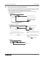
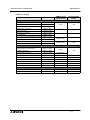
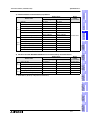
OPERATION MANUAL of GOT (sent separately)
Describes how to operate system screens and how to create and operate user screens, and covers all
of the F920GOT-K, F930GOT(-K), F940GOT and Handy GOT.
•
GOT-F900 SERIES OPERATION MANUAL (No. JY992D94701)
-
Screen creation software
GT Designer and FX-PCS-DU/WIN-E are supported.
MODEL CODE
09R804
OPERATION
MANUAL
-
To learn the display function of the GOT-F900.
To execute items in the HPP mode (such as
"PROGRAM LIST" and "MONITOR").
To execute "DEVICE MONITOR" and display alarms.
Applicable GOT
F920GOT-BBD-K-E
F920GOT-BBD5-K-E
F930GOT-BWD-E
F930GOT-BBD-K-E
F94"GOT-SWD-E
F94"GOT-LWD-E
F940WGOT-TWD-E
F94"GOT-SWD-(R)H-E
F94"GOT-LBD-(R)H-E
1-4
GOT-F900 SERIES (CONNECTION)
Introduction 1
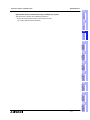
09R813
Two types of screen creation software are offered. The manual of the software you are using is required
(It is included with the software.).
GT Designer2
GT Designer2 (SW"D5C-GTD2-E) OPERATING MANUAL (separate manual)
Consult with the distributor from which you have purchased GT Designer2.
It is distributed as PDF
data saved in the CDROM of the SW"D5CGTD2-E.
GT Designer2 (SW"D5C-GTD2-E) REFERENCE MANUAL (separate manual)
Consult with the distributor from which you have purchased GT Designer2.
7
It is distributed as PDF
data saved in the CDROM of the SW"D5CGTD2-E.
OPERATING
MANUAL
To learn the types and specifications of GOT screens.
To learn the device range which can be monitored.
To learn common items to be set at the beginning.
To learn how to set and display the key window.
To learn how to use each object function.
To learn how to use the script function.
REFERENCE
MANUAL
-
It is distributed as PDF
data saved in the CDROM of the SW"D5CGOTR-PACKE.
GT Designer
•
GT Designer (SW"D5C-GOTR-PACKE) OPERATING MANUAL
-
To install the software to the personal computer.
To start up the software.
To learn how to connect the personal computer to the
GOT.
To learn the screen configuration of the software.
To learn the outline of diversified monitoring functions.
To learn the procedure to display the monitor screen.
To learn how to use the help function.
6
8
Connection of
MELSEC-F
FX Series PLC
•
5
Connection of
Peripheral
Equipment
-
To install the software to the personal computer.
To start up each software.
To learn how to connect the personal computer to the
GOT.
To learn the screen configuration of the software.
To lean the outline of diversified monitoring functions.
To learn the procedure to display the monitor screen.
To learn how to use the library function.
To learn how to draw graphics.
OPERATING
MANUAL
-
installation
and Wiring of
F940GOT
4
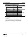
OPERATION MANUAL of screen creation software
•
3
installation
and Wiring of
Handy GOT
MODEL CODE
2
Outline
GT Designer2 is supported.
Applicable GOT
F920GOT-BBD-K-E
F920GOT-BBD5-K-E
F930GOT-BWD-E
F930GOT-BBD-K-E
F94"GOT-SWD-E
F94"GOT-LWD-E
F940WGOT-TWD-E
F94"GOT-SWD-(R)H-E
F94"GOT-LBD-(R)H-E
It is distributed as PDF
data saved in the CDROM of the SW"D5CGTD2-E.
Connection of
Two or More
GOT Units
Screen creation software
OPERATION
MANUAL
-
To learn the display function of the GOT-F900.
To execute items in the HPP mode (such as
"PROGRAM LIST" and "MONITOR").
To execute "DEVICE MONITOR" and display alarms.
9
Connection of
MELSEC-A
Series PLC
-
Specifications
GOT-F900 SERIES OPERATION MANUAL [GT Designer2] (No. JY997D09101)
10
1-5
Connection of
MELSEC-QnA
Series PLC
•
Introduction
1
GOT-F900 SERIES (CONNECTION)
•
Introduction 1
FX-PCS-DU/WIN-E OPERATION MANUAL (No: JY992D68301)
-
To install the software to the personal computer.
To start up the software.
To learn how to connect the personal computer to the
GOT.
To learn the screen configuration of the software.
To learn how to use the help function.
MODEL CODE
OPERATION
MANUAL
-
It is included with the
FX-PCS-DU/WIN-E.
09R910
1-6
GOT-F900 SERIES (CONNECTION)
Introduction 1
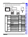
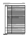
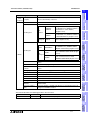
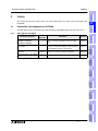
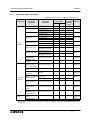
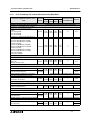
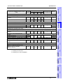
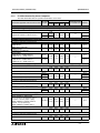
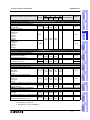
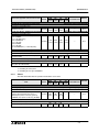
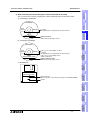
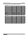
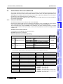
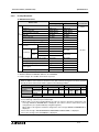
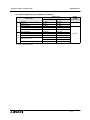
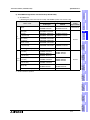
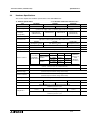
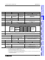
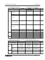
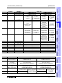
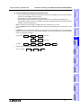
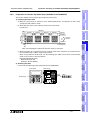
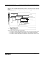
Abbreviations, Generic Names and Terms Used in This Manual
Abbreviations, generic names and terms used in this manual are shown below.
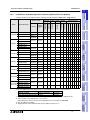
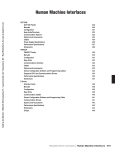
Types and Names of GOT-F900 Series
F930GOT
2
Handy GOT
Outline
F940GOT
F930GOT-K
F920GOT-K
G R IP S W
P O W E R
Specifications
3
P O W E R
F940WGOT-TWD-E,F940WGOT-TWD-C
F940GOT
F943GOT
F930GOT-K
Remarks
RS-422 ×1
RS-232C ×2
Japanese models
F940GOT-SWD,F940GOT-LWD
RS-422 ×1
RS-232C×1
Japanese models
F940GOT-SWD-E,F940GOT-LWD-E
F940GOT-SWD-C,F940GOT-LWD-C
RS-422 ×1
RS-232C×1
World spec models
F943GOT-SWD,F943GOT-LWD
RS-232C ×2
Japanese models
F930GOT-BBD-K
RS-422 ×1
RS-232C×1
World spec models
F930GOT-BBD-K-E, F930GOT-BBD-K-C
Japanese models
Japanese models
F930GOT-BWD
GOT-F900
Series
World spec models
F930GOT
F930GOT-BWD-E
F930GOT-BWD-C
F930GOT-BWD-T
RS-422 ×1
RS-232C ×1
F933GOT
F933GOT-BWD
RS-232C ×2
Japanese models
F920GOT-BBD5-K
RS-422 ×1
RS-232C ×1
Japanese models
5V
F920GOT-K
24V
F940 handy
GOT *1
F943 handy
GOT *1
F920GOT-BBD5-K-E, F920GOT-BBD5-K-C
F920GOT-BBD-K
F920GOT-BBD-K-E, F920GOT-BBD-K-C
F940GOT-SBD-H,F940GOT-LBD-H
F940GOT-SBD-RH,F940GOT-LBD-RH
F940GOT-SBD-H-E,F940GOT-LBD-H-E
F940GOT-SBD-RH-E,F940GOT-LBD-RH-E
F943GOT-SBD-H,F943GOT-LBD-H
F943GOT-SBD-RH,F943GOT-LBD-RH
F943GOT-SBD-H-E,F943GOT-LBD-H-E
F943GOT-SBD-RH-E,F943GOT-LBD-RH-E
RS-422 ×1
RS-232C ×1
World spec models
World spec models
Japanese models
World spec models
Japanese models
RS-422 ×1
World spec models
Japanese models
RS-232C ×1
World spec models
*1 In addition to the interface shown in the table, an RS-232C interface is built in for connection of a personal
computer.
-
Both the F940 Handy GOT and the F943 Handy GOT are generally called "Handy GOT".
1-7
5
installation
and Wiring of
Handy GOT
F940WGOT-TWD
F940WGOT
Built-in I/F
6
Connection of
Peripheral
Equipment
Model name
7
Connection of
Two or More
GOT Units
Name
8
Connection of
MELSEC-F
FX Series PLC
Generic
name
installation
and Wiring of
F940GOT
4
9
Connection of
MELSEC-A
Series PLC
1.2.1
10
Connection of
MELSEC-QnA
Series PLC
1.2
Introduction
1
GOT-F900 SERIES (CONNECTION)
1.2.2
Introduction 1
Information Offered by Model Name
GOT
F9"""GOT-####-#-#-#
1) 2) 3)
4) 5) 6) 7) 8) 9)
1) LC display size
2: 3 in.
3: 4 in.
4: 6 in. (7 in. in F940WGOT)
2) PLC connection specifications
0: RS-422,RS-232C Interface
3: RS-232C × 2ch interface
In the case of Handy GOT
0: RS-422 Interface
3: RS-232C interface
3) Screen shape
None: Standard
W: Wide screen
4) Screen color
T: TFT type 256-color LCD
S: STN type 8-color LCD
L: STN type black-and-white LCD
B: STN type blue LCD
5) Panel color
W: White
B: Black
6) Input power supply specifications
D: 24V DC
D5: 5V DC
7) Various keys
None: Not with a key
K: With a key
8) Type
None: Panel face installation type
H: Handy GOT
RH: Handy GOT
9) Overseas models
E:
C: In-built fonts vary depending on model.
T: For details, refer to the next page.
1-8
GOT-F900 SERIES (CONNECTION)
Introduction 1
In-built Fonts of Graphic Operation Terminal (Japanese/Overseas product)
Carefully confirm the in-built fonts when selecting a model from the F920GOT-K or F930GOT(-K).
$
$
$
$
$
$
$ $ $ $ $ $ $
F940WGOT-TWD-C
English
$
$
$
$
$
$
$ $ $ $ $ $ $
Japanese
English
$
−
$
$
$
$
$ $ $ $ $ $ $
English
Japanese
$
−
$
$
$
$
$ $ $ $ $ $ $
F940GOT-LWD-C
Chinese
(Simplified)
English
$
−
$
$
$
$
$ $ $ $ $ $ $
F930GOT-BBD-K
Japanese
English
$
$*5
$
−
−
−
$ $ $ $ $ $ $
F930GOT-BBD-K-E
English
Japanese
$
−
$
$*4
−
−
$ $ $ $ $ $ $
F930GOT-BBD-K-C
Chinese
(Simplified)
English
−
−
$
−
$
−
−
Japanese
English
$
$*5
$
−
−
−
$ $ $ $ $ $ $
F930GOT-BWD-E
English
Japanese
$
−
$
$*4
−
−
$ $ $ $ $ $ $
F930GOT-BWD-C
Chinese
(Simplified)
English
−
−
$
−
$
−
−
−
−
−
−
−
−
−
−
−
−
−
−
F940GOT-SWD-E
F940GOT-LWD-E
F940GOT-SWD-C
F930GOT-K
F93"GOT-BWD
F930GOT
F930GOT-BWD-T
F920GOT-BBD(5)-K
F920GOT-K
F920GOT-BBD(5)-K-E
Handy GOT
F94"GOT-LBD-H
F94"GOT-SBD-H-E
F94"GOT-LBD-H-E
F94"GOT-SBD-RH
Handy GOT F94"GOT-LBD-RH
(RH model) F94"GOT-SBD-RH-E
F94"GOT-LBD-RH-E
−
−
−
−
English
−
−
−
$
−
−
$
−
English
$
$
$
−
−
−
$ $ $ $ $ $ $
English
Japanese
$
$
$
$*4
−
−
$ $ $ $ $ $ $
English
−
−
$
−
$
$
−
Japanese
English
$
−
$
$
$
$
$ $ $ $ $ $ $
English
Japanese
$
−
$
$
$
$
$ $ $ $ $ $ $
Japanese
English
$
−
$
$
$
$
$ $ $ $ $ $ $
English
Japanese
$
−
$
$
$
$
$ $ $ $ $ $ $
−
−
−
*1 " in the GOT model name indicates 0 or 3. (The in-built interface varies as shown below.)
Name
F940GOT, F930GOT
−
Japanese
Chinese
F920GOT-BBD(5)-K-C
(Simplified)
F94"GOT-SBD-H
−
0
RS-422(1), RS-232C(1)
Handy GOT, Handy GOT RH model RS-422(1)
3
−
−
−
4
5
6
7
8
9
RS-232C(2)
RS-232C(1)
*2 A change on a system screen can be made in the screen creation software or GOT main unit.
*3 The font which can be displayed on a user screen
Depending on the OS, the font may not be displayed even if it is built in the GOT-F900.
*4 Only the Hangul is available.
*5 Supported from units manufactured in January, 2003 (serial No. 31****).
1-9
Connection of
MELSEC-A
Series PLC
F94"GOT-LWD
Outline
Japanese
Specifications
English
Chinese
(Simplified)
installation
and Wiring of
F940GOT
F940WGOT-TWD-E
3
installation
and Wiring of
Handy GOT
$ $ $ $ $ $ $
Connection of
Peripheral
Equipment
$
Connection of
Two or More
GOT Units
$
Connection of
MELSEC-F
FX Series PLC
$
French
Italian
$
German
Traditional
$
F94"GOT-SWD
F940GOT
Portuguese
Simplified
$
Spanish
Korean
English
Swedish
English
Japanese
Dutch
Can be
switched
to
F940WGOT-TWD
F940WGOT
2
At factory
GOT model name *1
Name
Shift JIS level-1
kanji set
Shift JIS level-2
kanji set
In-built fonts (user screen) *3
Language displayed on
system screen *2
Japanese English Korean Chinese
Western Europe
10
Connection of
MELSEC-QnA
Series PLC
1.2.3
Introduction
1
GOT-F900 SERIES (CONNECTION)
1.2.4
Introduction 1
Abbreviation List
Abbreviation/generic name/term
CPU
Description
QCPU(Q mode)
Generic name of Q00JCPU, Q00CPU, Q01CPU, Q02CPU, Q02HCPU,
Q06HCPU, Q12HCPU and Q25HCPU units
QCPU(A mode)
Generic name of Q02CPU-A, Q02HCPU-A and Q06HCPU-A units
QCPU
Generic name of QCPU (Q mode) and QCPU (A mode) units
QnACPU(large type)
Generic name of Q2ACPU, Q2ACPU-S1, Q3ACPU, Q4ACPU and
Q4ARCPU units
QnACPU(small type)
Generic name of Q2ASCPU, Q2ASCPU-S1, Q2ASHCPU and
Q2ASHCPU-S1 units
QnACPU
Generic name of QnACPU (large type) and QnACPU (small type) units
AnUCPU
Generic name of A2UCPU, A2UCPU-S1, A3UCPU and A4UCPU units
AnACPU
Generic name of A2ACPU, A2ACPU-S1 and A3ACPU units
AnNCPU
Generic name of A1NCPU, A2NCPU, A2NCPU-S1 and A3NCPU units
ACPU(large type)
Generic name of AnUCPU, AnACPU and AnNCPU units
A2US(H)CPU
Generic name of A2USCPU, A2USCPU-S1 and A2USHCPU-S1 units
AnS(H)CPU
Generic name of A1SCPU, A1SHCPU and A2SCPU units
A1SJ(H)CPU
Generic name of A1SJCPU-S3 and A1SJHCPU units
ACPU(small type)
Generic name of A2US(H)CPU, AnS(H)CPU and A1SJ(H)CPU units
ACPU
Generic name of ACPU (large type), ACPU (small type) and A1FXCPU units
FX0 Series
Generic name of FX0 Series main units
FX0S Series
Generic name of FX0S Series main units
FX1S Series
Generic name of FX1S Series main units
FX0N Series
Generic name of FX0N Series main units
FX1N Series
Generic name of FX1N Series main units
FX1 Series
Generic name of FX1 Series main units
FX Series
Generic name of FX Series main units
FX2 Series
Generic name of FX2 Series main units
FX2N Series
Generic name of FX2N Series main units
FX2C Series
Generic name of FX2C Series main units
FX2NC Series
Generic name of FX2NC Series main units
FXCPU
Generic name of FX0/FX0S/FX1S/FX0N/FX1N/FX1/FX/FX2/FX2N/FX2C/
FX2NC Series main units
FX Series GM
positioning unit
FX-10GM, FX-20GM, E-20GM, FX2N-10GM and FX2N-20GM
A Motion controller
CPU
Generic name of A171SCPU-S3, A171SHCPU, A172SHCPU and
A273UHCPU
FREQROL Series
A500/E500/S500 Series inverter
PLC by Omron
Generic name of C200H, C200HE, C200HG, C200HX, CQM1, CS1,
CPM1A, CPM2A, CPM2C and CJ1
PLC by Fuji Electric
Generic name of FLEX-PC N Series
(NB-RS1-AC, NB-RS1-DC, NJ-RS4, NJ-RS1 and NJ-RS2)
PLC by
PLC by Yasukawa
other
Electric
companies
PLC by Matsushita
Electric Works
Generic name of machine controllers CP-9200SH, MP-920 and MP-930
Generic name of FP0, FP2SH, FP2SH+FP2-CCU and FPΣ
PLC by Allen Bradley
Generic name of SLC 5/03 and SLC 5/04
PLC by Siemens
Generic name of SIMATIC S7-200, S7-300 and S7-400
1-10
GOT-F900 SERIES (CONNECTION)
Introduction 1
Abbreviation/generic name/term
PLC by
PLC by another
other
company
companies
OS
Description
Generic name of PLC manufactured by Omron, Fuji Electric, Yasukawa
Electric, Allen-Bradley or Siemens
Abbreviation of GOT system software
Introduction
1
2
Abbreviation of screen creation software for GOT-A900/GOT-F900 Series
GT Designer
GT
Designer
Others
SW"D5CGTWORKS-E
Integrated screen development software
for GOT900 Series (SW"D5C-GOTRPACKE + GT Simulator) (English version)
Screen creation software for GOT900
SW"D5C-GOTRSeries SW"D5C-GOTR-PACKE (English
PACKE
version)
Software dedicated to version upgrade
SW"D5C-GOTRfrom conventional version to latest
PACKEV
SW"D5C-GOTR-PACKE (English version)
DU/WIN
Abbreviation of screen creation software FX-PCS-DU/WIN-E for GOT-F900
Series
FX/WIN
Abbreviation of programming software FX-PCS/WIN-E for FX Series PLC
Data conversion
software
Abbreviation of data conversion software GOT Converter for GOT900
Series
Abbreviation of debugging software GOT Debugger
Object
Parts and setting data on the screen.
Windows95
Abbreviation of Microsoft Windows95
Windows98
Abbreviation of Microsoft Windows98
Abbreviation of Microsoft Windows NT Workstation 4.0
Windows 2000
Abbreviation of Microsoft Windows 2000 Professional
Windows
Generic name of Windows95, Windows98, Windows NT4.0 and
Windows2000
Personal computer
(PC)
Personal computer compatible with Windows to which GT Designer2, GT
Designer or DU/WIN is installed
This manual describes the following product in the new name.
GPPW
New name
GX Developer
Specifications
7
Windows NT4.0
Conventional name
6
Connection of
Two or More
GOT Units
Debugging software
5
8
Connection of
MELSEC-F
FX Series PLC
GT
Works
4
installation
and Wiring of
F940GOT
Screen creation software for GOT900
Series (English version)
9
Remarks
Abbreviation of software package SW"D5C-GPPW-E
Connection of
MELSEC-A
Series PLC
GT
SW"D5CDesigner2 GTD2-E
3
installation
and Wiring of
Handy GOT
SW"D5CGTWS-E
Integrated screen development software
for GOT900 Series (SW"D5C-GTWK2-E
+ A9GTSOFT-LKEY-P) (English version)
Connection of
Peripheral
Equipment
Integrated screen development software
for GOT900 Series (SW"D5C-GTD2-E +
GT Simulator2 + GT SoftGOT2)
(English version)
10
1-11
Connection of
MELSEC-QnA
Series PLC
GT
Works2
GT Designer2
SW"D5CGTWK2-E
Outline
Abbreviation of screen creation software for GOT-A900/GOT-F900 Series
GOT-F900 SERIES (CONNECTION)
Introduction 1
Abbreviation/generic name/term
Description
BK
Black
W
White
Y
Yellow
BR
Brown
BL
Blue
GY
Connection
O
diagram
PL
Gray
PK
Pink
FGR
Fresh green
SB
Sky blue
R
Red
GR
Green
Orange
Purple
1-12
Outline 2
GOT-F900 SERIES (CONNECTION)
Outline
This section describes the outline of PLC, bar code reader, printer, etc. which can be connected to the
GOT-F900.
The table below shows connection types supported by the GOT-F900 having the lastest OS version.
GOT type list and index
3
Description
Reference
F920GOT-K,
F930GOT, F930GOT-K,
F940GOT, F940WGOT
−
Name of each part, installation and power supply
wiring
Chapter 4
Handy GOT
−
Dedicated wiring and functions of Handy GOT such
as name of each part, installation, cables dedicated
to Handy GOT and switch control method
Chapter 5
Peripheral
equipment
Cable used to connect the personal computer to
transfer screen data and sequence programs
Chapter 6
Connection of two or more GOT
units
GOT-GOT
Wiring among up to four connected GOT units
Chapter 7
4
5
installation
and Wiring of
Handy GOT
Connection of peripheral
equipment
Specifications
Connected equipment
Connection
destination
Connection of
Peripheral
Equipment
6
Connection of
Two or More
GOT Units
7
Connection of
MELSEC-F FX
Series PLC
8
9
Connection of
MELSEC-A
Series PLC
2.1.1
Outline
Connection Type Supported by GOT-F900
installation
and Wiring of
F940GOT
2.1
2
10
2-1
Connection of
MELSEC-QnA
Series PLC
2.
Introduction
1
GOT-F900 SERIES (CONNECTION)
2.1.2
Outline 2
Connection type list and index
"$" indicates can connect. "−" indicates cannot connect.
Manufacturer
Connected
equipment
FX Series
A Series
A Motion controller
QnA Series
PLC by
Mitsubishi
Q Series (A mode)
-
RS-422
CPU direct connection
$
CPU direct connection
A computer link
CPU direct connection
A computer link
CPU direct connection
A computer link
Connection
of two or
Reference
more GOT
RS-232C
units
$
$
$
−
$
$
$
−
$
−
$
$
$
−
$
−
$
$
$
−
QnA computer link
$
$
$
CPU direct connection
−
−
−
A computer link
−
−
−
Chapter 8
Chapter 9
Chapter 9
Chapter 10
−
CPU direct connection
−
$
$
$
$
$
CPU direct connection
−
$
$
Serial communication unit
(CPU direct connection)
$
$
$
FX positioning unit
(10GM/20GM)
CPU direct connection
$
−
−
Chapter 12
FREQROL Series
(inverter)
CPU direct connection
$
−
−
Chapter 13
General-purpose
equipment such as
CPU direct connection
microcomputer board
$
$
$
Chapter 14
SYSMAC C Series by
Upper link
Omron
$
$
−
Chapter 15
FLEX-PC N Series by
Link unit
Fuji Electric
$
$
−
Chapter 16
CPU direct connection
Machine controller by (memo bus)
Yasukawa Electric
Memo bus unit
−
$
−
$
$
−
Q Series (multi CPU)
Others
Transmission
specifications
Serial communication unit
(CPU direct connection)
Q Series (Q mode)
PLC by other
companies
Connection
destination
Chapter 11
Chapter 11
Chapter 17
FP Series by
Matsushita Electric
Works
CPU direct connection
−
$
−
Chapter 18
SLC500/MicroLogix
Series by AllenBradley
CPU direct connection
−
$
−
Chapter 19
SIMATIC S7-200
SIMATIC S7-300
Series by Siemens
CPU direct connection
−
$
−
Chapter 20
General-purpose
printer
−
−
$
−
Chapter 21
Bar code reader
−
−
$
−
Chapter 22
For the details of the connection type in accordance with the OS version of the GOT-F900, refer to
section 3.1.
2-2
GOT-F900 SERIES (CONNECTION)
Outline 2
This section describes the outline of connection of the GOT-F900 to the PLC manufactured by
Mitsubishi.
" indicates that a PLC programming tool (personal computer) can be connected.
(Program transfer and monitoring are available using the programming software for the FX/A/QnA/Q
Series.)
FX Series PLC
1) CPU direct connection (RS-422)
GOT-F900 is connected to the programming port of the FX Series PLC. When a personal computer
is connected to the GOT-F900, sequence programs can be created.
E ith e r o n e u n it*1 ( a p e r s o n a l c o m p u te r a n d
o n e u n it in F 9 4 0 W G O T )
installation
and Wiring of
Handy GOT
R S -2 3 2 C
M E L S E C - F X S e r ie s
(F X /F X 1 /F X 2 /F X 2 C )
P e rs o n a l
c o m p u te r
G O T -F 9 0 0
P r in te r
B a r c o d e re a d e r
By attaching the optional RS-422 communication board, a programming port can be added. As a
result, a GOT-F900 or personal computer (for sequence programs) can be connected to each port.
F X
F X
1 N
2 N
-4 2 2 -B D
-4 2 2 -B D
E ith e r o n e u n it*1 ( a p e r s o n a l c o m p u te r a n d
o n e u n it in F 9 4 0 W G O T )
P O W E R
P e rs o n a l
c o m p u te r
G O T -F 9 0 0
P r in te r
B a r c o d e re a d e r
Connection of
Two or More
GOT Units
M E L S E C - F X S e r ie s
(F X 0 /F X 0 S /F X 1 S /F X 0 N /
F X 1 N /F X 2 N /F X 2 N C )
E ith e r o n e u n it*1 ( a p e r s o n a l c o m p u te r a n d
o n e u n it in F 9 4 0 W G O T )
8
P O W E R
R S -2 3 2 C
( o n ly in F X
1 S
/F X
1 N
/F X
2 N
)
G O T -F 9 0 0
P e rs o n a l
c o m p u te r
P r in te r
B a r c o d e re a d e r
Connection of
MELSEC-F FX
Series PLC
R S -4 2 2
6
7
R S -2 3 2 C
R S -4 2 2
4
5
P O W E R
R S -4 2 2
3
Connection of
Peripheral
Equipment
"
Outline
PLC by Mitsubishi
*1 Excluding the F920GOT-K
9
Connection of
MELSEC-A
Series PLC
2.2.1
2
Specifications
This section explains by means of diagrams the connection types of PLC, bar code reader, printer and
personal computer (for sequence programs) connected to the GOT-F900.
The same type of equipment cannot be connected. (For example, connection of two PLC units or
connection of two bar code readers are not allowed.)
The compatible connection types vary according to the model of the GOT-F900. For details, refer to the
specifications shown later.
installation
and Wiring of
F940GOT
Outline of Connection Types
10
2-3
Connection of
MELSEC-QnA
Series PLC
2.2
Introduction
1
GOT-F900 SERIES (CONNECTION)
Outline 2
2) CPU direct connection (RS-232C)
By attaching the optional RS-232C communication board, a programming port can be added. As a
result, the GOT-F900 or personal computer (for sequence programs) can be connected to each port.
(A personal computer, printer or bar code reader can be connected only when the GOT is equipped
with two RS-232C channels.)
F X
F X
0 N
1 N
-2 3 2 A D P , F X
-2 3 2 -B D , F X
2 N C
2 N - 2
-2 3 2 A D P
3 2 -B D
E ith e r o n e u n it*2 ( a p e r s o n a l c o m p u te r a n d
o n e u n it in F 9 4 0 W G O T )
P O W E R
R S -2 3 2 C
R S -2 3 2 C
G O T -F 9 0 0
M E L S E C - F X S e r ie s
(F X 1 S /F X 1 N /F X 2 N )
P e rs o n a l
c o m p u te r
*1
P r in te r
B a r c o d e re a d e r
E ith e r o n e u n it*2 ( a p e r s o n a l c o m p u te r a n d
o n e u n it in F 9 4 0 W G O T )
P O W E R
R S -2 3 2 C
R S -2 3 2 C
( in F X
/F X
1 S
1 N
/F X
2 N
/F X
2 N
G O T -F 9 0 0
C )
P e rs o n a l
c o m p u te r
*1
P r in te r
B a r c o d e re a d e r
*1 Excluding the 5V type F920GOT-K.
*2 Excluding the F920GOT-K
3) Connection of two or more GOT units
Up to four GOT-F900 units can be connected to the programming port or the optional communication
port of the FX Series PLC.
F X
F X
F X
0 N
1 N
2 N
-2 3 2 A D P , F X 2 N C -2 3 2 A D P
-4 2 2 -B D /F X 1 N -2 3 2 -B D
-4 2 2 -B D /F X 2 N -2 3 2 -B D
E ith e r o n e u n it
. . . . . . .
P O W E R
P O W E R
R S -4 2 2
M E L S E C - F X S e r ie s
(F X 0 /F X 0 S /F X 1 S /F X 0 N /
F X 1 N /F X 2 N /F X 2 N C /F X /
F X 1 /F X 2 /F X 2 C )
R S -2 3 2 C
G O T -F 9 0 0
R S -4 2 2
o r
R S -2 3 2 C
( in F X
F X 2 N
C
1 S
)
/F X
1 N
/F X
2 N
/
*1
( O n ly o n e H a n d y G O T u n it c a n b e
c o n n e c te d a t th e e n d .)
. . . . . . .
P O W E R
P r in te r
B a r c o d e
re a d e r
E ith e r o n e u n it
P O W E R
R S -2 3 2 C
G O T -F 9 0 0
*1
( O n ly o n e H a n d y G O T u n it c a n b e
c o n n e c te d a t th e e n d .)
P r in te r
B a r c o d e
re a d e r
*1 Excluding the F920GOT-K
2-4
GOT-F900 SERIES (CONNECTION)
Outline 2
1) CPU direct connection (RS-422)
GOT-F900 is connected to the programming port of the A/QnA Series PLC or the motion controller.
When a personal computer is connected to the GOT-F900, programs can be created.
The serial communication unit of the Q/QnA Series PLC is connected through CPU direct
connection. The GOT-F900 can be connected to only either one between two ports. (Connecting two
GOT-F900 units to one serial communication unit is not allowed.)
E ith e r o n e u n it
*1
3
Specifications
C P U
S e r ia l c o m m u n ic a tio n u n it
P O W E R
R S -2 3 2 C
R S -4 2 2
M E L S E C - A S e r ie s
M E L S E C - Q n A S e r ie s
M o tio n c o n tr o lle r *1
P e rs o n a l
c o m p u te r
G O T -F 9 0 0
2
Outline
Q/QnA/A Series PLC
Introduction
1
E ith e r o n e u n it
P r in te r
B a r c o d e re a d e r
*1
installation
and Wiring of
F940GOT
4
P O W E R
P e rs o n a l
c o m p u te r
P r in te r
B a r c o d e re a d e r
*1 Excluding the F920GOT-K
*2 Excluding the 5V type F920GOT-K.
GOT-F900 is connected to the programming por t of the Q Series PLC (Multi-CPU system
applicable*1) or the serial communication unit of the Q/QnA Series PLC.
When a personal computer is connected to the GOT-F900, programs can be created.
The serial communication unit of the Q/QnA Series PLC is connected through CPU direct
connection. The GOT-F900 can be connected to only either one between two ports. (Connecting two
GOT-F900 units to one serial communication unit is not allowed.)
(A personal computer, printer or bar code reader can be connected only when the GOT is equipped
with two RS-232C channels.)
E ith e r o n e u n it*3 ( a p e r s o n a l c o m p u te r a n d
o n e u n it in F 9 4 0 W G O T )
Connection of
Two or More
GOT Units
7
P O W E R
R S -2 3 2 C
R S -2 3 2 C
M E L S E C -Q
S e r ie s
P e rs o n a l
c o m p u te r
G O T -F 9 0 0
P r in te r
B a r c o d e re a d e r
E ith e r o n e u n it*3 ( a p e r s o n a l c o m p u te r a n d
o n e u n it in F 9 4 0 W G O T )
Connection of
MELSEC-F FX
Series PLC
8
P O W E R
R S -2 3 2 C
R S -2 3 2 C
( in M E L S E C - Q n A /Q
*
2
G O T -F 9 0 0
S e r ie s )
P e rs o n a l
c o m p u te r
P r in te r
B a r c o d e re a d e r
*1 GOT-F900 can be connected to the multi-CPU system only when the connection consists of QCPU.
(A motion controller or CPU of a personal computer cannot be used concurrently.)
*2 Excluding the 5V type F920GOT-K.
*3 Excluding the F920GOT-K
9
Connection of
MELSEC-A
Series PLC
C P U
S e r ia l c o m m u n ic a tio n u n it
6
Connection of
Peripheral
Equipment
2) CPU direct connection (RS-232C)
installation
and Wiring of
Handy GOT
5
10
2-5
Connection of
MELSEC-QnA
Series PLC
R S -2 3 2 C
R S -4 2 2
*
2
( in M E L S E C - Q n A /Q
G O T -F 9 0 0
S e r ie s )
GOT-F900 SERIES (CONNECTION)
Outline 2
3) A computer link connection
GOT-F900 is connected to the A/QnA Series PLC by attaching the A CPU computer link unit.
E ith e r o n e u n it*2
A c o m p u te r lin k u n it
R S -4 2 2
o r
R S -2 3 2 C
C o m p u te r lin k u n it fo r
M E L S E C - A S e r ie s
P O W E R
R S -2 3 2 C
G O T -F 9 0 0
*1
P r in te r
*1 Excluding the 5V type F920GOT-K.
B a r c o d e
re a d e r
*2 Excluding the F920GOT-K.
4) Connection of two or more GOT units
In the A/QnA Series PLC, up to four GOT-F900 units can be connected to programming ports (RS422) of the CPU.
In the QnA/Q Series PLC, to each of the CPU programming port (RS-232C) and the attached serial
communication unit, up to four GOT-F900 units can be connected.
The serial communication unit of the Q/QnA Series PLC is connected through CPU direct
connection. The GOT-F900 can be connected to only either one between two ports. (Connection of
two GOT-F900 units to one serial communication unit is not allowed.)
C P U
S e r ia l c o m m u n ic a tio n u n it
M E L S
M E L S
M E L S
M o tio
E C -A
E C -Q
E C -Q
n c o n
R S -4 2 2
o r
R S -2 3 2 C
S e r ie s
n A S e r ie s
S e r ie s
tr o lle r *1
M E L S E C -Q
R S o
R S -2
S e r ie
4 2 2
r
3 2 C
s
. . . . . . .
P O W E R
G O T -F 9 0 0
*1
P O W E R
R S -2 3 2 C
*1
P r in te r
( O n ly o n e H a n d y G O T u n it c a n b e
c o n n e c te d a t th e e n d .)
. . . . . . .
P O W E R
G O T -F 9 0 0
E ith e r o n e u n it
B a r c o d e
re a d e r
E ith e r o n e u n it
P O W E R
R S -2 3 2 C
( O n ly o n e H a n d y G O T u n it c a n b e
c o n n e c te d a t th e e n d .)
P r in te r
B a r c o d e
re a d e r
*1 Excluding the F920GOT-K
FX positioning unit (10GM/20GM)
CPU direct connection (RS-422)
GOT-F900 is connected to the programming port of the FX Series positioning unit (10GM/20GM).
(A personal computer, printer or bar code reader can be connected only when the GOT is equipped
with RS-422 and RS-232C.)
E ith e r o n e u n it
P O W E R
R S -2 3 2 C
R S -4 2 2
1 0 G M /2 0 G M
G O T -F 9 0 0
*1
P r in te r
B a r c o d e
re a d e r
*1 Excluding the F920GOT-K
2-6
GOT-F900 SERIES (CONNECTION)
Outline 2
FREQROL Series
CPU direct connection (RS-422)
GOT-F900 is connected to the (built-in) PU port of the FREQROL Series inverter.
In the A500 Series, the GOT-F900 can be connected also to the computer link option (FR-A5NR).
Outline
S ta tio n N o . 1
S ta tio n N o . 3 1
. . . . . . . . . .
P O W E R
In v e rte r
In v e rte r
3
Specifications
One GOT-F900 unit can control up to 10 inverters.
PLC by Other Companies
This section describes the outline of connection of the GOT-F900 to the PLC manufactured by other
companies.
General-purpose equipment
1) Microcomputer connection
The GOT-F900 can be connected to the serial communication port of a personal computer or
microcomputer board.
R S -4 2 2
o r
R S -2 3 2 C
P e rs o n a l c o m p u te r o r
G O T -F 9 0 0
m ic r o c o m p u te r b o a r d
P O W E R
R S -2 3 2 C
P r in te r
*1
*1 Excluding the 5V type F920GOT-K.
B a r c o d e
re a d e r
6
*2 Excluding the F920GOT-K.
2) Connection of two or more GOT units
Up to four GOT-F900 units can be connected to the serial communication connector of a personal
computer or microcomputer board.
E ith e r o n e u n it*2
R S -4 2 2
o r
R S -2 3 2 C
P e rs o n a l c o m p u te r o r
G O T -F 9 0 0
m ic r o c o m p u te r b o a r d
. . . . .
P O W E R
*1
P O W E R
R S -2 3 2 C
( O n ly o n e H a n d y G O T u n it c a n b e
c o n n e c te d a t th e e n d .)
*1 Excluding the F920GOT-K
P r in te r
B a r c o d e
re a d e r
PLC by Omron
Upper link connection
One GOT-F900 unit can be connected to a port having the upper link communication function of the
SYSMAC C Series (C200H/C200HE/C200HG/C200HX/CQM1/CS1/CPM1A/CPM2A/CPM2C/CJ1).
R S -4 2 2
o r
R S -2 3 2 C
E ith e r o n e u n it*2
S Y S M A C C
P O W E R
G O T -F 9 0 0
R S -2 3 2 C
*1
*1 Excluding the 5V type F920GOT-K.
P r in te r
7
8
*2 Excluding the F920GOT-K.
U p p e r lin k u n it
5
installation
and Wiring of
Handy GOT
E ith e r o n e u n it*2
4
9
Connection of
MELSEC-A
Series PLC
2.2.2
installation
and Wiring of
F940GOT
*1 Excluding the F920GOT-K
Connection of
Peripheral
Equipment
In v e rte r
Connection of
Two or More
GOT Units
*1
Connection of
MELSEC-F FX
Series PLC
G O T -F 9 0 0
2
B a r c o d e re a d e r
10
*2 Excluding the F920GOT-K.
2-7
Connection of
MELSEC-QnA
Series PLC
S ta tio n N o . 0
Introduction
1
GOT-F900 SERIES (CONNECTION)
Outline 2
PLC by Fuji Electric
Link unit connection
One GOT-F900 unit can be connected to the link unit of the FLEX-PC N Series (NB/NJ/NS) PLC.
L in k u n it
E ith e r o n e u n it
R S -4 2 2
o r
R S -2 3 2 C
F L E X -P C N
P O W E R
R S -2 3 2 C
G O T -F 9 0 0
P r in te r
*1
B a r c o d e re a d e r
*1 Excluding the F920GOT-K
PLC by Yasukawa Electric
Memo bus unit connection
One GOT-F900 unit can be connected to the MEMOBUS port of the machine controller or the memo
bus unit.
C P U o r m e m o b u s u n it
C P 9 2 0 0 S H
M P 9 2 0
M P 9 3 0
R S -4 2 2
o r
R S -2 3 2 C
E ith e r o n e u n it
P O W E R
R S -2 3 2 C
G O T -F 9 0 0
P r in te r
*1
B a r c o d e re a d e r
*1 Excluding the F920GOT-K
PLC by Matsushita Electric Works
CPU direct connection (RS-232C)
One GOT-F900 unit can be connected to the FP Series CPU or computer communication unit.
C P U
C C U
E ith e r o n e u n it*2
P O W E R
R S -2 3 2 C
R S -2 3 2 C
G O T -F 9 0 0
F P S e r ie s
P r in te r
*1
B a r c o d e re a d e r
E ith e r o n e u n it*2
P O W E R
R S -2 3 2 C
R S -2 3 2 C
F P 2 -C C U
G O T -F 9 0 0
*1
*1 Excluding the 5V type F920GOT-K.
P r in te r
B a r c o d e re a d e r
*2 Excluding the F920GOT-K.
PLC by Allen-Bradley
CPU direct connection (RS-232C)
One GOT-F900 unit can be connected to the SLC500/MicroLogix Series CPU.
(A personal computer, printer or bar code reader can be connected only when the GOT is equipped
with two RS-232C channels.)
C P U
E ith e r o n e u n it*2
P O W E R
R S -2 3 2 C
S L C 5 0 0 S e r ie s
R S -2 3 2 C
G O T -F 9 0 0
*1
*1 Excluding the 5V type F920GOT-K.
P r in te r
B a r c o d e re a d e r
*2 Excluding the F920GOT-K.
2-8
GOT-F900 SERIES (CONNECTION)
Outline 2
CPU direct connection (RS-232C)
By connecting the HMI adapter to the SIMATIC S7-300 Series CPU, one GOT-F900 unit can be
connected to the SIMATIC S7-300 Series CPU.
By connecting the PC/PPI cable to the SIMATIC S7-200 Series CPU, one GOT-F900 unit can be
connected to the SIMATIC S7-300 Series CPU.
(A personal computer, printer or bar code reader can be connected only when the GOT is equipped
with two RS-232C channels.)
C P U
E ith e r o n e u n it*2
P O W E R
R S -2 3 2 C
P r in te r
B a r c o d e re a d e r
*2 Excluding the F920GOT-K.
4
Others
Not only the PLC, a printer or bar code reader can be connected to the GOT-F900.
The connection shown below is available also in the Handy GOT. However, because the rear panel of
the Handy GOT must be removed when a cable is connected to the RS-232C connector, the waterproof
ability and the operability (operation of the Handy GOT while it is held by hand) are lost. Accordingly, the
connection shown below is not practical for the Handy GOT.
Printer
Connection of printer (RS-232C)
When a printer is connected to the GOT-F900, the alarms and contents of screens (as hard copy)
can be printed.
installation
and Wiring of
F940GOT
G O T -F 9 0 0
*2
*1
5
installation
and Wiring of
Handy GOT
R S -2 3 2 C
*1 Excluding the 5V type F920GOT-K.
Connection of
Peripheral
Equipment
6
P O W E R
R S -2 3 2 C
G O T -F 9 0 0
P r in te r
*1
*1 Excluding the F920GOT-K and Handy GOT
7
Bar code reader
Connection of
Two or More
GOT Units
Connection of bar code reader
When a bar code reader is connected to the GOT-F900, bar codes can be read.
P O W E R
B a r c o d e re a d e r
G O T -F 9 0 0
8
*1
Connection of
MELSEC-F FX
Series PLC
R S -2 3 2 C
*1 Excluding the F920GOT-K and Handy GOT
Connection of
MELSEC-A
Series PLC
9
10
2-9
Connection of
MELSEC-QnA
Series PLC
2.2.3
Specifications
3
H M I A d a p te r
P C /P P I C a b le
S IM A T IC S 7 - 3 0 0 S e r ie s
S IM A T IC S 7 - 2 0 0 S e r ie s
2
Outline
PLC by Siemens
Introduction
1
GOT-F900 SERIES (CONNECTION)
Outline 2
MEMO
2-10
Specifications 3
GOT-F900 SERIES (CONNECTION)
Specifications
This section allows to confirm connectable equipment, device specifications, versions of applicable
screen creation software and hardware specifications.
There are following five types of OS.
F940WGOT
Remarks
940W system
F940GOT, Handy GOT
940 system
F930GOT
930 system
F930GOT-K
930 system
F920GOT-K
920 system
The first product is Ver. 4.60 or later.
4
5
How to Confirm OS Version of GOT-F900
When the power of the GOT-F900 is turned on, the screen shown below is displayed for several
seconds to indicate the series name and the version number ("version 2.10" in the lower right position).
(The period of time to be displayed can be changed by the screen creation software or the GOT.)
6
F940GOT
Connection of
Peripheral
Equipment
MELSEC-GOT
Series name
Copyright(C) 1998
Ver.2.10
Connection of
Two or More
GOT Units
7
Version
Mitsubishi Electric Corporation
8
On the rear panel of the GOT-F900 main unit, the nameplate indicating the manufacturer's serial
number, the model name and the OS version is adhered. However, because the OS can be upgraded, it
is recommended to confirm it using the method above.
9
Connection of
MELSEC-A
Series PLC
3.1.1
Name
installation
and Wiring of
Handy GOT
GOT-F900 Series
Specifications
OS type
3
installation
and Wiring of
F940GOT
Some equipment (PLC manufactured by Mitsubishi or other companies, microcomputer board, bar code
reader, printer, etc.) cannot be connected depending on the OS (operating system) version of the GOTF900.
In this section, you can check the OS version, and check whether it corresponds to the equipment to be
connected.
Outline
OS Version and Correspondence to Connected Equipment of GOT-F900
Connection of
MELSEC-F FX
Series PLC
3.1
2
10
3-1
Connection of
MELSEC-QnA
Series PLC
3.
Introduction
1
GOT-F900 SERIES (CONNECTION)
3.1.2
Specifications 3
PLC, Positioning unit, Inverter Manufactured by Mitsubishi
Connected equipment name and series
name
RS-232C/
RS-422
OS version
Connection of two
940W
940
930
920 or more GOT units Reference
system system system system
MITSUBISHI Electric
MELSEC-F FX Series (CPU direct connection)
Connection type name [FXCPU direct connection]
Connection to programming port in FX CPU
FX0,FX0S,FX1S,FX0N,FX1N,FX2N,FX2NC
FX,FX2C
FX2N +FX2N-422-BD
FX1S +FX1N-422-BD
FX1N +FX1N-422-BD
RS-422
1.00
1.00
1.00
1.00
or later or later or later or later
$*1
8.2.1
RS-232C
1.00
1.00
1.00 1.20*2
or later or later or later or later
$*1
8.2.2
Connection to extended communication port
FX1S+FX1N-232-BD
FX1S+FX1N-CNV-BD+FX0N-232ADP
FX1S+FX1N-CNV-BD+FX2NC-232ADP
FX1N+FX1N-232-BD
FX1N+FX1N-CNV-BD+FX0N-232ADP
FX1N+FX1N-CNV-BD+FX2NC-232ADP
FX2N+FX2N-232-BD
FX2N+FX2N-CNV-BD+FX0N-232ADP
FX2N+FX2N-CNV-BD+FX2NC-232ADP
FX2NC+FX0N-232ADP
FX2NC+FX2NC-232ADP
MELSEC-A Series (CPU direct connection)
Connection type name [ACPU direct connection]
Connection to programming port in A CPU
AnN, AnA, AnS, AnSJ, AnSH, A1SH, A2C, A2CJ,
A0J2H, AnU
A2US(S1), A2USH, A1FX
RS-422
MELSEC-A Series (computer link connection)
1.00
1.00
1.00
1.00
or later or later or later or later
$*1
9.2.1
Connection type name [A computer link connection]
Connection to computer link unit
RS-422
1.00
1.00
1.00 1.20*2
AJ71UC24, A1SJ71C24-R2, A1SJ71UC24-R2,
RS-232C or later or later or later or later
A1CPUC24-R2, A2CCPU24
9.2.2
AJ71UC24, A1SJ71C24-R4, A1SJ71UC24-R4
Motion controller (CPU direct connection)
9.2.3
Connection type name [ACPU direct connection]
Connection to programming port in A CPU
A171SCPU-S3, A171SHCPU, A172SHCPU,
A173UHCPU, A273UHCPU
RS-422
MELSEC-QnA/QnAS Series (CPU direct connection)
1.00
1.00
1.00
1.00
or later or later or later or later
$*1
9.2.1
Connection type name [QnACPU direct connection]
Connection to programming port in QnA CPU
QnACPU, Q4ARCPU, Q2ACPU, Q2AHCPU,
Q2ASCPU, Q2ASH(S1)CPU
RS-422
MELSEC-QnA/QnAS Series (CPU direct connection)
1.00
3.00
2.00
1.00
or later or later or later or later
$*1
10.2.1
Connection type name [QnA computer link connection]
Connection to serial communication unit
AJ71QC24, AJ71QC24-R4, A1SJ71QC24
AJ71QC24, AJ71QC24-R2, A1SJ71QC24,
A1SJ71QC24-R2
RS-422
1.00
3.00
2.00 1.20*2
RS-232C or later or later or later or later
MELSEC-A Series (computer link connection)
10.2.2
*1
$
10.2.3
Connection type name [A computer link connection]
Connection to computer link unit
AJ71UC24, A1SJ71C24-R4
A1SJ71UC24-R4
1.00
3.00
2.00 1.20*2
RS-232C or later or later or later or later
RS-422
9.2.2
9.2.3
3-2
GOT-F900 SERIES (CONNECTION)
Specifications 3
Connection of two
940W
940
930
920 or more GOT units Reference
system system system system
Connection type name [QCPU direct connection]
Connection to programming port in Q CPU
Q02CPU, Q02HCPU, Q06HCPU, Q12HCPU,
Q25HCPU
RS-232C
1.00
4.10
2.20
1.00
or later or later or later or later
$*1
11.2.1
Q00JCPU,Q00CPU,Q01CPU
RS-232C
1.30
6.30
4.30
1.00
or later or later or later or later
$*1
11.2.1
MELSEC-Q Series (CPU direct connection)
Connection type name [QCPU direct connection]
Connection to serial communication unit
1.00
4.10
2.20 1.20*2
RS-232C or later or later or later or later
RS-422
MELSEC-Q Series (CPU direct connection)
(Q multiple PLC system Ver. B or later)
11.2.2
11.2.3
Connection type name [QCPU direct connection]
Q02CPU, Q02HCPU, Q06HCPU, Q12HCPU,
Q25HCPU
RS-232C
1.30
6.30
4.30
1.00
or later or later or later or later
$*1
11.2.1
11.2.2
Connection to serial communication unit
QJ71C24
1.30
6.30
4.30 1.20*2
RS-232C or later or later or later or later
RS-422
QJ71C24, QJ71C24-R2
FX Series positioning unit (CPU direct connection)
11.2.3
Connection type name [GM direct connection]
Connection to programming port in GM CPU
FX2N-10GM, FX2N-20GM, FX-10GM, FX-20GM,
E-20GM
RS-422
FREQROL Series inverter (CPU direct connection)
1.10
6.10
4.10
or later or later or later
12.2.1
Connection type name [INV direct connection]
Connection to computer link (PU port, etc.)
S500 Series (R-485 port built-in type only)
A500 Series (PU port, FR-A5NR)
E500 Series (PU port)
RS-422
1.10
6.10
4.10
or later or later or later
$: Can connect
13.2.1
: Cannot connect
installation
and Wiring of
F940GOT
4
Connection to programming port in Q CPU
5
installation
and Wiring of
Handy GOT
QJ71C24, QJ71C24-R2
3
6
Connection of
Peripheral
Equipment
QJ71C24
2
Outline
MELSEC-Q Series (CPU direct connection)
OS version
Specifications
RS-232C/
RS-422
7
Connection of
Two or More
GOT Units
*1 Excluding the 920 system
*2 Excluding the 5 V type F920GOT-K.
Connection of
MELSEC-F FX
Series PLC
8
Connection of
MELSEC-A
Series PLC
9
10
3-3
Connection of
MELSEC-QnA
Series PLC
Connected equipment name and series
name
Introduction
1
GOT-F900 SERIES (CONNECTION)
3.1.3
Specifications 3
PLC Manufactured by Other Companies
The table below describes the product evaluated in each series.
Connected equipment name and series name
RS-232C/
RS-422
General
Microcomputer (general-purpose communication)
OS version
Connection of two
Reference
940W
940
930
920
or more GOT units
system system system system
Connection type name [Micro computer connection]
Connection to serial communication port
Personal computer or microcomputer board
equipped with RS-232C or RS-422 interface
RS-422
RS-232C
Omron
SYSMAC COM1/C200H Series (upper link)
Connection to RS-232C port built in CPU
CQM1 (built-in upper link)
- CQM1-CPU21
CQM1H (built-in upper link)
- CQM1H-CPU61
Connection to host link unit
C200H/C200HS
- C200H-CPU01 + C200H-LK202-V1
- C200HS-CPU31 + C200H-LK202-V1
C200H/C200HS
- C200H-CPU01 + C200H-LK201-V1
- C200HS-CPU31 + C200H-LK201-V1
1.00
or later
1.00
1.00 1.20*2
or later or later or later
14.2.2
Connection type name [SYSMAC C]
1.00
1.00
1.00
or later or later or later
1.40
6.40
4.40
RS-232C
or later or later or later
RS-232C
14.2.1
$*1
1.20*2
or later
1.20*2
or later
15.2.2
15.2.2
RS-422
15.2.1
1.00
1.00
1.00 1.20*2
or later or later or later or later
RS-232C
SYSMAC CS1 Series (upper link)
15.2.2
Connection type name [SYSMAC C]
Connection to RS-232C port built in CPU
CS1G-CPU45-V1
1.00
6.00
4.00 1.20*2
or later or later or later or later
15.2.2
RS-422
1.00
6.00
4.00 1.20*2
RS-232C
or later or later or later or later
RS-232C
15.2.1
15.2.2
15.2.2
RS-232C
Connection to serial communication board/unit
CS1W-SCB41 (port 1, port 2)
CS1W-SCU21 (port 1, port 2)
SYSMAC α Series (upper link)
Connection type name [SYSMAC C]
Connection to RS-232C port built in CPU
C200HX-CPU44-Z
1.62
6.62
4.62 1.20*2
or later or later or later or later
15.2.2
RS-422
1.62
6.62
4.62 1.20*2
RS-232C or later or later or later or later
15.2.1
15.2.2
RS-232C
Connection to serial communication board
C200HW-COM06-V1 (port A, port B)
SYSMAC CPM 1A/2A/2C Series (upper link)
Connection type name [SYSMAC C]
Connection to peripheral port built in CPU
CPM1A-10CDR-A + CQM1-CIF01
(Level conversion of peripherique port) +
Conversion connector [25pin → 9pin]
CPM2C-10CDR-D + CPM2C-CIF01-V1
(RS232C et port peripherique)
CPM2C-10CDR-D + CPM2C-CN111
Connection to RS-232C port built in CPU
RS-232C
1.62
6.62
4.62 1.20*2
or later or later or later or later
15.2.1
CPM2A-30CDR-A
RS-232C
1.62
6.62
4.62 1.20*2
or later or later or later or later
15.2.2
SYSMAC CJ1 Series (upper link)
Connection type name [SYSMAC C]
Connection to RS-232C port built in CPU
CJ1G-CPU44
RS-232C
1.62
6.62
4.62 1.20*2
or later or later or later or later
15.2.2
3-4
GOT-F900 SERIES (CONNECTION)
Specifications 3
Fuji Electric
FLEX-PC N Series (link unit)
RS-232C
Connection type name [FLEX-PC N]
2
1.00
1.00
1.00
or later or later or later
16.2.2
RS-422
16.2.1
1.00
1.00
1.00
or later or later or later
1.00
5.00
3.00
or later or later or later
17.2.1
RS-422
RS-232C
1.00
5.00
3.00
or later or later or later
17.2.1
17.2.2
Connection to memo bus unit
Matsushita Electric Works
FP Series (CPU direct connection)
Connection type name [FP]
Connection to COM port built in CPU
FP0 Series
- FP0-T32CT
1.10
6.10
4.10 1.20*2
RS-232C
FP2SH Series
or later or later or later or later
- FP2-C2
Connection to tool port built in CPU
FP0 Series
1.10
6.10
4.10 1.20*2
- FP0-T32CT
RS-232C
or later or later or later or later
FP2SH Series
- FP2-C2
Connection to COM port for communication with computer
FP2SH Series
1.10
6.10
4.10 1.20*2
RS-232C
- FP2-C2+FP2-CCU
or later or later or later or later
Σ Series (CPU direct connection)
FPΣ
18.2.1
18.2.1
18.2.1
Connection type name [FP]
RS-232C
1.62
6.62
4.62 1.20*2
or later or later or later or later
1.62
6.62
4.62 1.20*2
or later or later or later or later
9
Connection to COM port for communication with computer
FPG-C32T+FPG-COM1 (port 1)
FPG-C32T+FPG-COM2 (port 1, port 2)
RS-232C
$: Can connect
7
8
Connection to tool port built in CPU
FPG-C32T
6
Connection of
MELSEC-F FX
Series PLC
- MP920 + CP-217IF
- CP9200SH + CP-217IF
installation
and Wiring of
Handy GOT
RS-232C
5
Connection of
Peripheral
Equipment
Connection type name [Machine controller]
Connection to RS-232C port built in CPU
Connection of
Two or More
GOT Units
16.2.2
installation
and Wiring of
F940GOT
4
RS-232C
Yasukawa Electric
Machine controller (memo bus connection)
MP920, MP930, CP9200SH
Specifications
3
: Cannot connect
*1 Excluding the 920 system
*2 Excluding the 5 V type F920GOT-K.
Connection of
MELSEC-A
Series PLC
Connection to RS-232C port built in CPU
NJ Series
- NJ-CPU-B16
Connection to link unit
NB Series
- NB-RS1-AC
NJ Series
- NJ-RS4
NS Series
- NS-RS1
NB Series
- NB-RS1-AC
NJ Series
- NJ-RS2
NS Series
- NS-RS1
OS version
Connection of two
Reference
940W
940
930
920
or more GOT units
system system system system
Outline
RS-232C/
RS-422
10
3-5
Connection of
MELSEC-QnA
Series PLC
Connected equipment name and series name
Introduction
1
GOT-F900 SERIES (CONNECTION)
Connected equipment name and series name
Specifications 3
RS-232C/
RS-422
OS version
Connection of two
Reference
940W
940
930
920
or more GOT units
system system system system
Allen-Bradly
SLC500 Series (CPU direct connection)
Connection type name [SLC500]
Connection to port built in CPU
SLC5/04 (1747-L541)
RS-232C
1.00
2.00
2.00 1.20*2
or later or later or later or later
MicroLogix Series (CPU direct connection)
Connection to port built in CPU
MicroLogix 1000 (D Series and later)
- 1761-L10BWA
Micro Logix 1000 analog
- 1761-L20AWA-5A
Micro Logix 1200
- 1762-L24BWA
Micro Logix 1500
- 11764-24BWA(base) + 1764-LSP(CPU)
RS-232C
1.00
6.00
4.00 1.20*2
or later or later or later or later
19.2.1
SIMATIC S7 Series (SIMATIC S7)
Connection to port built in CPU
S7-313 (6ES7 1AD03-0AB0) + HMI adapter (6ES7
1.00
5.00
3.00 1.20*2
RS-232C
972-0CA11-0XA0)
or later or later or later or later
SIMATIC S7-200 Series (CPU direct connection)
RS-232C
19.2.1
Connection type name [SLC500]
SIEMENS AG
SIMATIC S7-300/400 Series (CPU direct connection)
Connection to port built in CPU
S7-216-2 (6ES7 216-2BD00-0XB0) + PC/PPI
cable (6ES7 901-3BF20-0ZA0)
20.2.1
SIMATIC S7 Series (SIMATIC S7)
1.20
6.20
4.20
or later or later or later
$: Can connect
20.2.1
: Cannot connect
*1 Excluding the 920 system
*2 Excluding the 5 V type F920GOT-K.
3.1.4
Others
The table below describes the product evaluated in each series.
Connected equipment name and series
name
OS version
RS-232C/
Connection of two
Reference
940
930
920
RS-422 940W
or more GOT units
system system system system
General
General-purpose printer for RS-232C
SIMATIC S7 Series (RS-232C general-purpose printer)
Connection to RS-232C port
Connection to ESC/P compatible printer
equipped with built-in RS-232C interface
LBP450 (laser printer for A4 size) [Cannon]
LP8000SX (laser printer for A4 size) [EPSON]
RS-232C
Bar code reader
1.00
1.00
1.00
or later or later or later
21.2.1
SIMATIC S7 Series (Bar code reader)
Connection to RS-232C port
BCH5432-STA [Nihon Denki Seiki]
RS-232C
1.00
2.00
2.00
or later or later or later
$: Can connect
21.2.1
: Cannot connect
3-6
GOT-F900 SERIES (CONNECTION)
Specifications 3
Version of Screen Creation Software and Correspondence to GOT-F900
Three types of screen creation software are offered the SW"DSC-GTD2-E, SW"D5C-GOTR-PACKE
and FX-PCS-DU/WIN-E as follows.
2
Generic name
GT Designer2
Screen creation software
SW"D5C-GTWORKS-E
SW"D5C-GOTR-PACKE
GT Designer
FX-PCS-DU/WIN-E
DU/WIN
Applicable GOT-F900 Series models and the correspondence to the connected equipment (related to
the OS version also) vary depending on the version of the screen creation software. In this section, you
can check the version of your screen creation software and confirm applicable GOT models and
connectable equipment.
The table in Section 3.2.2 shows the screen creation software version corresponding to each GOTF900. The table in Section 3.2.3 shows the screen creation software version corresponding to each
connected equipment. Compare these two tables. The newer version is required.
3
Specifications
SW"D5C-GTWS-E
SW"D5C-GTWK2-E
SW"D5C-GTD2-E
Name
4
installation
and Wiring of
F940GOT
Screen creation software
Outline
Types of screen creation software
installation
and Wiring of
Handy GOT
5
Connection of
Peripheral
Equipment
6
Connection of
Two or More
GOT Units
7
Connection of
MELSEC-F FX
Series PLC
8
Connection of
MELSEC-A
Series PLC
9
10
3-7
Connection of
MELSEC-QnA
Series PLC
3.2
Introduction
1
GOT-F900 SERIES (CONNECTION)
3.2.1
Specifications 3
How to Conform Version of Screen Creation Software
You can confirm the version by displaying the help screen after starting up the screen creation software
in the personal computer or by confirming the contents indicated on the FD or CD-ROM of the product.
1) When confirming the version using the help function of the software
For the GT Designer2, GT Designer and DU/WIN, you can confirm the version by selecting
[Help (H)]-[About (A)] from the menu bar.
a) GT Designer2
Version ("1.00A" in this case)
"SW1" indicates the major version.
SW"D5C-GTD2-J (Japanese)
SW"D5C-GTD2-E (English)
b) GT Designer
In the case of Version SW5 or later
Version 5.09K
Small version
SW5
SW"D5C-GOTR-PACKE
"SW5" indicates the large version. An
alphabet at the end indicates the small
version.
In the case of Version SW4 or former
An alphabet at the end indicates the small
version.
Version SW" 00A
Small version
c) DU/WIN
Version
Model name
3-8
GOT-F900 SERIES (CONNECTION)
Specifications 3
2) When confirming the version through the contents indicated on the media
You can confirm the version by checking the contents indicated on the media of the product.
a) GT Designer2 (CD-ROM)
Introduction
1
2
MELSEC
A version
(An alphabet at the end indicates the small version.)
3
Specifications
DATE
9812AA
disc
Outline
MITSUBISHI
MODEL
SW1D5C-GTD2-E
SW1D5C-GTD2-E
"SW1" indicates the large version.
b) GT Designer (CD-ROM)
installation
and Wiring of
F940GOT
4
MITSUBISHI
MELSEC
MODEL
SW2D5C-GOTR-PACKE
In the case of Version SW4 or former
A version
(An alphabet at the end indicates the small version.)
In the case of Version SW5 or later
"5.05F" is indicated.
5
installation
and Wiring of
Handy GOT
DATE
9812AA
disc
SW2D5C-GOTR-PACKE
"SW2" indicates the large version.
6
Connection of
Peripheral
Equipment
c) DU/WIN (FD)
SW0PC-FX-DU/WIN-E
FD model name
The model name of the software package is "FX-PCS-DU/WIN-E".
Version
Connection of
MELSEC-F FX
Series PLC
8
Connection of
MELSEC-A
Series PLC
9
10
3-9
Connection of
MELSEC-QnA
Series PLC
V 1.0
Connection of
Two or More
GOT Units
7
GOT-F900 SERIES (CONNECTION)
3.2.2
Specifications 3
Screen Creation Software Version Corresponding to GOT-F900 Series
Japanese version
"D5C-GTD2-J
SW"
Version
"D5C-GOTR-PACK
SW"
Version
FX-PCS-DU/WIN
Version
F940WGOT
SW1-A (1.00A)
SW5-F (5.05F)
2.50
F940GOT
SW1-A (1.00A)
SW1-A
2.00
F943GOT
SW1-A (1.00A)
SW1-A
2.00
F930GOT-K
SW1-A (1.00A)
SW5-26C (5.26C)
−
F930GOT
SW1-A (1.00A)
SW1-H
2.20
F933GOT
SW1-A (1.00A)
SW1-H
2.20
F920GOT-K (5V)
SW1-A (1.00A)
SW5-26C (5.26C)
2.70
F920GOT-K (24V)
SW1-C (1.02C)
−
−
F940 Handy GOT
SW1-A (1.00A)
SW1-D
2.10
F940 Handy GOT (RH model)
SW1-A (1.00A)
SW5-F (5.05F)
2.50
F943 Handy GOT
SW1-A (1.00A)
SW1-D
2.10
F943 Handy GOT (RH model)
SW1-A (1.00A)
SW5-F (5.05F)
2.50
ET-900
SW1-A (1.00A)
SW1-D
2.00
GOT-F900 Series
- """ of the "SW"D5C-GOTRE-PACKE" and "SW"DC-GTD2-E" indicates a number.
English version
"D5C-GTD2-E
SW"
"D5C-GOTRE-PACK
SW"
Version
FX-PCS-DU/WIN-E
Version
F940WGOT
SW1-C (1.02C)
SW5-F (5.05F)
2.50
F940GOT
SW1-C (1.02C)
SW1-E
2.00
F930GOT-K
SW1-C (1.02C)
SW5-26C (5.26C)
2.70
F930GOT
SW1-C (1.02C)
SW1-H
2.30
F920GOT-K (5V)
SW1-C (1.02C)
SW5-26C (5.26C)
2.70
F920GOT-K (24V)
SW1-C (1.02C)
−
−
F940 Handy GOT
SW1-C (1.02C)
SW1-D
2.10
F940 Handy GOT (RH model)
SW1-C (1.02C)
SW5-F (5.05F)
2.50
F943 Handy GOT
SW1-C (1.02C)
SW1-D
2.10
F943 Handy GOT (RH model)
SW1-C (1.02C)
SW5-F (5.05F)
2.50
GOT-F900 Series
-
""" of the "SW"D5C-GOTRE-PACKE" and "SW"DC-GTD2-E" indicates a number.
3-10
GOT-F900 SERIES (CONNECTION)
Specifications 3
Screen Creation Software Corresponding to Each Connected Equipment
Products in Japanese
"D5C-GTD2-J
SW"
Version
"D5C-GOTR-PACK
SW"
Version
FX-PCS-DU/WIN
Version
SW1-A (1.00A)
SW1-A
2.00
SW1-A (1.00A)
SW2-A
2.30
SW1-A (1.00A)
SW4-F
2.40
SW1-A (1.00A)
SW5-P (5.13P)
−
SW1-A (1.00A)
SW5-K (5.09K)
2.50
Microcomputer connection
(general-purpose communication)
SW1-A (1.00A)
SW1-A
SYSMAC C by Omron
SW1-A (1.00A)
SW1-A
FLEX-PC N by Fuji Electric
SW1-A (1.00A)
--(Not applicable)
CP9200SH by Yasukawa Electric
SW1-A (1.00A)
SW4-F
--(Not applicable)
FP by Matsushita Electric Works
SW1-A (1.00A)
SW5-K (5.09K)
2.60
Connected equipment (abbreviation)
2
Mitsubishi
Q computer link
QCPU direct connection (multi CPU system)
Q computer link (multi CPU system)
GM direct connection (FX positioning unit)
INV direct connection (inverter)
Other companies
2.00
SLC500 by Allen-Bradley
SW1-A (1.00A)
SW1-H
2.30
MicroLogix by Allen-Bradley
SW1-A (1.00A)
SW5-F (5.05F)
2.50
SIMATIC S7-300 by Siemens AG
SW1-A (1.00A)
SW5-F (5.05F)
2.40
SIMATIC S7-200 by Siemens AG
SW1-A (1.00A)
SW5-P (5.13P)
2.60
Others
Printer (with built-in RS-232C)
SW1-A (1.00A)
SW1-A
2.00
Bar code reader
SW1-A (1.00A)
SW1-H
2.20*1
CC-Link
SW1-A (1.00A)
SW5-P (5.13P)
2.40
-
""" of the "SW"D5C-GOTRE-PACKE" and "SW"DC-GTD2-E" indicates a number.
*1 The F930GOT is applicable in Version 2.30 and later.
Specifications
QCPU direct connection
4
installation
and Wiring of
F940GOT
QnA computer link
3
5
installation
and Wiring of
Handy GOT
QnACPU direct connection
6
Connection of
Peripheral
Equipment
A computer link
7
Connection of
Two or More
GOT Units
ACPU direct connection
Outline
FXCPU direct connection
Connection of
MELSEC-F FX
Series PLC
8
Connection of
MELSEC-A
Series PLC
9
10
3-11
Connection of
MELSEC-QnA
Series PLC
3.2.3
Introduction
1
GOT-F900 SERIES (CONNECTION)
Specifications 3
Products in English
Connected equipment (abbreviation)
"D5C-GTD2-E
SW"
"D5C-GOTRSW"
PACKE Version
FX-PCS-DU/WIN-E
Version
SW1-E
2.00
SW2-A
2.30
SW4-F
2.40
SW5-P (5.13P)
−
SW5-K (5.09K)
2.50
Mitsubishi
FXCPU direct connection
SW1-C (1.02C)
ACPU direct connection
SW1-C (1.02C)
A computer link
SW1-C (1.02C)
QnACPU direct connection
SW1-C (1.02C)
QnA computer link
SW1-C (1.02C)
QCPU direct connection
SW1-C (1.02C)
Q computer link
SW1-C (1.02C)
QCPU direct connection (multi CPU system)
SW1-C (1.02C)
Q computer link (multi CPU system)
SW1-C (1.02C)
GM direct connection (FX positioning unit)
SW1-C (1.02C)
INV direct connection (inverter)
SW1-C (1.02C)
Other companies
Microcomputer connection
(general-purpose communication)
SW1-C (1.02C)
SYSMAC C by Omron
SW1-C (1.02C)
FLEX-PC N by Fuji Electric
SW1-C (1.02C)
Not applicable
CP9200SH by Yasukawa Electric
SW1-C (1.02C)
SW4-F
−
FP by Matsushita Electric Works
SW1-C (1.02C)
SW5-K (5.09K)
2.60
SW1-E
2.00
SLC500 by Allen-Bradley
SW1-C (1.02C)
SW1-H
2.30
MicroLogix by Allen-Bradley
SW1-C (1.02C)
SW5-F (5.05F)
2.50
SIMATIC S7-300 by Siemens AG
SW1-C (1.02C)
SW5-F (5.05F)
2.40
SIMATIC S7-200 by Siemens AG
SW1-C (1.02C)
SW5-P (5.13P)
2.52
Others
Printer (with built-in RS-232C)
SW1-C (1.02C)
SW1-E
2.00
Bar code reader
SW1-C (1.02C)
SW1-H
2.30
-
""" of the "SW"D5C-GOTRE-PACKE" and "SW"DC-GTD2-E" indicates a number.
3-12
GOT-F900 SERIES (CONNECTION)
Specifications 3
Devices in GOT-F900
The table below shows intrinsic devices built in the GOT-F900.
Because these internal devices have no relevance to the devices in the connected PLC or the memory
of the microcomputer board, they can be used without regard to the connected equipment.
These internal devices in the GOT-F900 can be rewritten by the status monitoring function, the switch
function and the numeric value input function, and used for lamp indicator, numeric value display, switch
condition, etc.
Allocation of devices for internal processing
GB132 to GB255
Available
Decimal
GB256 to GB1023 Available (excluding the F920GOT-K)
Word
device
GD (GOT internal device)
GD0 to GD99
Not available except devices in table
below
GD100 to GD127
Available
6
Decimal
GD128 to GD1023 Available (excluding the F920GOT-K)
-
GB 0 to GB 131 and GD 0 to GD 99 are used for the processing inside the GOT-F900.
Note, however, that the devices with functions shown below are available for user use.
Device
Function
Device
7
Function
GD0
Display of current time (second)*2
GB0 to GB12
Not to be used
GD1
Display of current time (minute)*2
GB13
Communication error
(hour)*2
GD2
Display of current time
GB14,GB15
Not to be used
GD3
Display of current time (day)*2
GB16
Buzzer (Issued once) *1
GD4
Display of current time (month)*2
GB17
Buzzer (Issued three times) *1
GB18
Buzzer (Issued continuously) *1
Not to be used
(year)*2
GD5
Display of current time
GD6
Display of current time (day of week)*2
GB19 to 131
GD7
Not to be used
GB132 to GB1023 For user's use
GD8,GD9
Upper limit of input numerical value (32 bit)
GD10,GD11
Lower limit of input numerical value (32 bit)
*1 Buzzer is available in the following OS.
F940WGOT Ver. 1.40 or later
F940GOT
Ver. 6.40 or later
F930GOT
Ver. 4.40 or later
F930GOT-K Ver. 4.60 or later (From first product)
F920GOT-K Ver. 1.00 or later (From first product)
Handy GOT Ver. 6.40 or later
GD12
Numerical value, Ascii input
GD13 to GD99
Not to be used
GD100 to GD1023 For user's use
*2 Which cannot be input or changed
Connection of
Peripheral
Equipment
Not available except devices in table
below
3-13
Connection of
Two or More
GOT Units
GB (GOT internal device)
GB0 to GB131
5
8
Connection of
MELSEC-F FX
Series PLC
Bit
device
Device number
representation
Available range
installation
and Wiring of
Handy GOT
GT Designer2 and GT Designer from the first version
DU/WIN from Version 2.50 and later
Device name
4
installation
and Wiring of
F940GOT
Available screen creation software
3
9
Connection of
MELSEC-A
Series PLC
3.3.1
2
Outline
This section explains the device range of the PLC available in the GOT-F900. The maximum device
range which can be set in the screen creation software is shown here. The device specifications vary
depending on the model of the PLC even if the series name is equivalent. (Example: In the FX Series,
the FX1N PLC has fewer devices than in the FX2N PLC.)
When looking at the table, change the device range shown in the table with the device range available in
the actually connected PLC.
Specifications
Device Names Which can be Monitored
10
Connection of
MELSEC-QnA
Series PLC
3.3
Introduction
1
GOT-F900 SERIES (CONNECTION)
3.3.2
Specifications 3
PLC by Mitsubishi
1) MELSEC-F FX Series
Setting range
Device name
GT Designer (2)
Input (X)
X000~X377
X000~X377
Output (Y)
Y000~Y377
X000~X377
Auxiliary relay (M)
M0000~M3071
M0000~M3071
Special auxiliary relay (M)
Bit
device State (S)
M8000~M8255
M8000~M8255
S0~S999
S0~S999
Timer contact (T)
T0~T255
T0~T255
Counter contact (C)
C000~C255
C0~C255
GOT internal bit register (GB) *1
GB132~GB1023
GB132~GB1023
T0~T255
T0~T255
Present value
Timer (T)
Set value
16 bits
Counter (C)
32 bits
*2
Set value
*2
C0~C199
C0~C199
CS0~CS199
Present value
C200~C255
Decimal
C200~C255
CS200~CS255
Set value *2
Word
device Data register (D) (Including file register*2) D0~D7999
D0~D7999
File register (D)
D1000~D7999
D1000~D7999
Special data register (D)
D8000~D8255
D8000~D8255
Index register
GOT internal data register (GD)
-
Octal
−
TS0~TS255
Present value
*1
Device number
representation
DU/WIN
Z
*3
Z
V
*3
V
GD100~GD1023
GD100~GD1023
In specifying word devices for the bar code reader, C200 to C255 and CS200 to CS255 are not available.
*1 GB132 to GB255 and GD100 to GD127 in the F920GOT-K
*2 In data changes, the condition shown below is present.
Condition enabling data changes
While the GOT is connected to the FX Series PLC, data cannot be changed in set values (specified
directly) of timers and counters and file registers in the following condition.
PLC status
Memory type
Memory
cassette
Write-protect
attached to PLC switch status
Entry code
Present
Not present
While PLC is stopped
RAM
EEPROM
−
OFF
$
$
%*2
While PLC is running
EPROM RAM
EEPROM
ON
−
−
OFF
%*1
%*1
$
%*3
EPROM
ON
−
%*1
%*1
%*2
The following error messages are displayed on the screen only when a timer, counter or file register is
accessed through a Numeric Input or ASCII input.
*1 When data of a set value (specified directly) of a timer or counter is tried to be changed, the error
message "WRITE IS PROHIBITED." is displayed. (Set values of timers and counters can be
changed if they are specified indirectly using data registers.)
When data of a file register is tried to be changed, the error message "WRITE IS PROHIBITED." is
displayed.
*2 The error message "THE OPERATION IS DISABLED BY ENTRY CODE." is displayed.
*3 The error message "PLC IS RUNNING." is displayed.
*3 Available only in the GT Designer2.
3-14
GOT-F900 SERIES (CONNECTION)
Specifications 3
Device number
representation
Introduction
1
Hexadecimal
2
Setting range
X0~X1FFF
X0~X0FFF
Output (Y)
Y0~Y1FFF
Y0~Y0FFF
Internal relay (M) *1
M0~M8191
M0~M8191
Latch relay (L) *1
L0~L8191
L0~L8191
Annunciator (F)
F0~F2047
F0~F2047
B0~B1FFF
B0~B1FFF
T0~T2047
Coil
TC0~TC2047
Contact
CT0~CT1023
Coil
CC0~CC1023
−
C0~C1023
Decimal
−
GOT internal bit register (GB) *2
GB132~1023
GB132~1023
Data register (D)
D0~D8191
D0~D8191
Special data register (D)
D9000~D9255
D9000~D9255
Link register (W)
W0~W1FFF
W0~W1FFF
T0~T2047
Set value *3
T0~T2047
TS0~TS2047
Present value CN0~CN1023
Word
Counter (C)
device
Set value
File register (R)
*3
*3
Accumulator (A)
GOT internal data register (GD)
*2
5
C0~C1023
CS0~CS1023
C0~C1023
R0~R8191
R0~R8191
Decimal
6
−
A0~A1
Index register (Z, V) *4
Hexadecimal
Z0~Z6(Z0=Z)
Z
V0~V6(V0=V)
V
GD100~1023
GD100~1023
Connection of
Peripheral
Equipment
Timer (T)
Present value TN0~TN2047
*1 Latch relays (L) are treated as internal relays (M) in the GOT-F900.
*2 GB132 to GB255 and GD100 to GD127 in the F920GOT-K
*3 In data changes, the condition shown below is present.
7
Condition enabling data changes
While the GOT is connected to the A Series PLC or A Series computer link unit, data cannot be
changed in set values (specified directly) of timers and counters and file registers in the following
condition.
PLC status
Memory type
Entry code
Present
Not present
While PLC is stopped
4
installation
and Wiring of
Handy GOT
Counter (C)
M9000~M9255
TT0~TT2047
3
While PLC is running
RAM
ROM
RAM
ROM
$
%*1
$
%*1
%*2
%*2
The following error messages are displayed on the screen only when a timer, counter or file register is
accessed through a Numeric Input or ASCII input.
*0
*1 When data of a set value (specified directly) of a timer or counter is tried to be changed, the error
message "WRITE IS PROHIBITED." is displayed. (Set values of timers and counters can be
changed if they are specified indirectly using data registers.)
When data of a file register is tried to be changed, the error message "WRITE IS PROHIBITED." is
displayed.
*2 The error message "THE OPERATION IS DISABLED BY ENTRY CODE." is displayed.
*4 In computer link connection, index registers (Z, V) cannot be monitored or written.
3-15
Connection of
Two or More
GOT Units
Timer (T)
M9000~M9255
Contact
Hexadecimal
8
Connection of
MELSEC-F FX
Series PLC
Link relay (B)
Bit
device Special internal relay (M)
Decimal
installation
and Wiring of
F940GOT
Input (X)
Specifications
DU/WIN
9
Connection of
MELSEC-A
Series PLC
GT Designer (2)
10
Connection of
MELSEC-QnA
Series PLC
Device name
Outline
2) MELSEC-A Series (including motion controller)
GOT-F900 SERIES (CONNECTION)
Specifications 3
3) MELSEC-QnA/Q (Q mode) Series
Setting range
Device name
GT Designer (2)
Input (X)
X0~X1FFF
X0~X1FFF
Output (Y)
Y0~Y1FFF
Y0~Y1FFF
Internal relay (M)
M0~M32767
M0~M32767
Hexadecimal
Latch relay (L)
L0~L32767
L0~L32767
Annunciator (F)
F0~F32767
F0~F32767
Decimal
Link relay (B)
B0~B7FFF
B0~B7FFF
Special link relay (SB)
SB0~SB7FF
SB0~SB7FF
TT0~TT32767
T0~T32767
Bit
Timer (T)
device
Counter (C)
Contact
Coil
TC0~TC32767
−
Contact
CT0~CT32767
C0~C32767
Coil
Retentive timer (ST)
SM0~SM2047
SM0~SM2047
Contact
SS0~SS32767
SS0~SS32767
Coil
SC0~SC32767
SC0~SC32767
S0~S32767
S0~S32767
Step relay (S)
GOT internal bit register (GB)
*1
Data register (D)
GB132~GB1023
GB132~GB1023
D0~D32767
D0~D32767
Special register (SD)
SD0~SD2047
SD0~SD2047
Link register (W)
W0~W7FFF
W0~W7FFF
Special link register (SW)
SW0~SW7FF
SW0~SW7FF
Timer (T)
Counter (C)
Present value TN0~TN32767
Hexadecimal
−
Present value CN0~CN32367
C0~C32367
−
Set value
Decimal
T0~T32767
−
Set value
Hexadecimal
−
CC0~CC32767
Special relay (SM)
Word
device
DU/WIN
Device
number
representation
−
Retentive timer (present value) (SN)
SN0~SN32767
SN0~SN32767
File register (R)
R0~R32767 *2
R0~R32767 *2
Index register (Z)
Z0~Z15
Z
GOT internal data register (GD) *1
GD100~GD1023
GD100~GD1023
Decimal
*1 GB132 to GB255 and GD100 to GD127 in the F920GOT-K
*2 File registers in a block changed over by the RSET instruction are regarded as targets.
Restriction in set monitor in computer link for A Series
When a computer link unit for the A Series is attached to the QnA CPU and the GOT-F900 is connected
to the unit, the set monitor range is equivalent to that in the AnA CPU, and the restriction shown in the
table below is applied (by the restriction in computer link).
Setting range
Device name
Timer (Present value)
Timer (Set value)
Word
Counter (Present value)
device
Counter (Set value)
File register
GT Designer (2)
DU/WIN
TN0 to TN255
T0 to T255
−
−
CN0 to C255
CN0 to C255
−
−
−
−
Device
number
representation
Decimal
−: Monitor and write disabled
3-16
Connection of
MELSEC-A
Series PLC
Connection of
MELSEC-F FX
Series PLC
Connection of
Two or More
GOT Units
Connection of
Peripheral
Equipment
installation
and Wiring of
Handy GOT
installation
and Wiring of
F940GOT
Specifications
Outline
Introduction
Specification of PLC number when using Q multiple PLC system
Specify the PLC number when appointing the device.
0: CPU connected (Control PLC if connected to the link)
1 to 4: CPU with the specified number
3-17
Connection of
MELSEC-QnA
Series PLC
GOT-F900 SERIES (CONNECTION)
Specifications 3
1
2
3
4
5
6
7
8
9
10
GOT-F900 SERIES (CONNECTION)
Specifications 3
4) FX Series GM positioning unit (GM direct connection)
Setting range
Device name
GT Designer (2)
DU/WIN
Input (X) *1
X0~X377
X0~X377
Output (Y)
Y0~Y67
Y0~Y67
M0~M511
M0~M511
M9000~M9175
M9000~M9175
Bit
Internal relay (M)
device
Special auxiliary relay (SM)
GOT internal bit register (GB)
GB132~1023
GB132~1023
Data register (D)
D0~D3999
D0~D3999
Special data register (SD)
D9000~D9313
D9000~D9313
Word File register (R)
device
Index register (Z, V)
GOT internal data register (GD)
D4000~D6999
D4000~D6999
Z0~Z6 (32 bits)
Z (32 bits)
V0~V6 (16 bits)
V (16 bits)
GD100~1023
GD100~1023
Device
number
representation
Octal
Decimal
*1 Devices cannot be written.
3-18
GOT-F900 SERIES (CONNECTION)
Specifications 3
5) FREQROL Series inverter (INV direct connection)
Setting range
GOT internal data register (GD)
A0:"~A7:"
Pr0:"~Pr993:"
Decimal
PG0:"~PG89:"
3
SP108:"~SP127:"
GD100~1023
4
Specify the station number using either of the following methods.
a) Station No. specification (direct) : Specify the station number of the inverter when setting the
device.
[Available setting range: 0 to 31]
"##" indicates a set numeric value.
Set "GD100".
Program operation ###
Parameter display ###
PG0:100
Pr0:100
5
6
Connection of
Peripheral
Equipment
b) Station No. specification (indirect) : Specify the station number of the inverter indirectly using 16-bit
GOT internal registers (GD100 to GD115) when setting the
device.
Multiple inverters can be changed on one screen.
[Available setting range: 100 to 115]
* The station No. corresponds to each device of GD100 to
GD115.
Station No. ###
Outline
GB132~1023
""" indicates the station number of the monitored inverter.
GOT-F900 screen
2
Specifications
Parameter (Pr)
Word
Program operation (PG)
device
Special parameter (SP)
S0:"~S7:"
installation
and Wiring of
F940GOT
Alarm code (A)
DU/WIN
installation
and Wiring of
Handy GOT
Control status (S)
Bit
device GOT internal bit register (GB)
GT Designer (2)
Device
number
representation
7
Connection of
Two or More
GOT Units
Indicate GD100
Connection of
MELSEC-F FX
Series PLC
8
Connection of
MELSEC-A
Series PLC
9
10
3-19
Connection of
MELSEC-QnA
Series PLC
Device name
Introduction
1
GOT-F900 SERIES (CONNECTION)
3.3.3
Specifications 3
PLC Units Manufactured by Other Companies
1) Microcomputer board (general-purpose communication)
Setting range
Device name
GT Designer (2)
Bit data (M)
Bit
Special memory (M) *2
device
GOT internal bit register (GB) *4
Word data (D) *3
Word
Special memory (M) *2
device
GOT internal data register (GD) *4
DU/WIN
M0~M2047 *1
M0~M2047
M8000~M8063
M8000~M8063
GB132~GB1023
GB132~GB1023
D0~D4095
D0~D4095
D8000~D8015
D8000~D8015
GD100~GD1023
GD100~GD1023
Device
number
representation
Decimal
*1 The bit data (M) is available in the GT Designer version SW1-E and later.
*2 The special memory is offered for special application (such as interrupt output and communication error
information) in the GOT.
*3 In the F920GOT-K, D0 to D1023 are available.
*4 GB132 to GB255 and GD100 to GD127 in the F920GOT-K
2) SYSMAC C Series manufactured by Omron
Setting range
Device name
GT Designer (2)
I/O relay
..000000~..614315
Internal auxiliary relay
WR00000~WR51115
Data link relay (LR)
LR00000~LR19915
Auxiliary memory relay (AR)
AR00000~AR95915
Bit
device Holding relay (HR)
Timer contact (TIM)
Counter contact (CNT)
GOT internal bit register (GB)
*3
Data memory (DM)
Timer (Present value) (TIM)
Counter (Present value) (CNT)
Word Extension data memory (EM)
device (current bank)
DU/WIN
00000~51115
−
L0000~L6315
*1
A0000~A2715
HR00000~HR51115
H0000~H9915
TIM0~TIM2047
T000~T511
CNT0~CNT2047
C000~C511
GB132~GB1023
GB132~GB1023
DM0~DM9999
TIM0~TIM2047
Device
number
representation
Decimal
D0000~D9999
*2
CNT0~CNT2047
*2
T000~T511
C000~C511
EM0000~EM9999
−
Extension data memory
(E0 to EC: 13 banks)
E00000~E09999
:
EC0000~EC9999
−
GOT internal data register (GD) *3
GD100~GD1023
GD100~GD1023
Hexadecimal
Decimal
*1 When the SYSMACα, CPM1A/2A/2C, CS1 or CS1J Series is connected, auxiliary memory relays (AR)
cannot be set to ON or OFF. Do not use AR in the key operation setting (bit).
*2 Set values cannot be read.
*3 GB132 to GB255 and GD100 to GD127 in the F920GOT-K
3-20
GOT-F900 SERIES (CONNECTION)
Specifications 3
3) FLEX-PC N Series manufactured by Fuji Electric
Input (X)
X0~X7FF
X0~X7FF
Output (Y)
Y0~Y7FF
Y0~Y7FF
M0~M1FFF
M0~M1FFF
L0~L1FFF
L0~L1FFF
Internal relay (M)
Bit
device Latch relay (L)
State (S)
S0~S7FF
S0~S7FF
Special internal relay (M)
M800~M81FF
M800~M81FF
GOT internal bit register (GB)
GB132~GB1023
GB132~GB1023
Timer (T)
T0~T3FF
T0~T3FF
Counter (C)
C0~C1FF
C0~C1FF
Data register (D)
Word
Special data register (D)
device
Link register (W)
D0~D2FFF
D0~D2FFF
D8000~D81FF
D8000~D81FF
W0~W3FFF
W0~W3FFF
File register (R)
R0~R7FFF
R0~R7FFF
GOT internal data register (GD)
GD100~GD1023
GD100~GD1023
2
Outline
DU/WIN
3
Hexadecimal
Specifications
GT Designer2
Device
number
representation
4
installation
and Wiring of
F940GOT
Setting range
Device name
Introduction
1
Input register (IW)
Word
Holding register (MW)
device
GOT internal data register (GD)
IB0~IBFFFF
−
Hexadecimal
MB0~MB4095F
−
*1
GB132~GB1023
−
Decimal
IW0~IW7FFF
−
Hexadecimal
MW0~MW32767
−
Hexadecimal
GD100~GD1023
−
Decimal
GT Designer (2)
6
7
Connection of
Two or More
GOT Units
Input relay (IB)
Bit
Coil (MB)
device
GOT internal bit register (GB)
DU/WIN
Device
number
representation
*1 Word address (decimal) + Bit position (hexadecimal)
Connection of
MELSEC-F FX
Series PLC
8
Connection of
MELSEC-A
Series PLC
9
10
3-21
Connection of
MELSEC-QnA
Series PLC
Setting range
Device name
Connection of
Peripheral
Equipment
4) Machine controller MP900/CP9200SH Series manufactured by Yasukawa Electric
installation
and Wiring of
Handy GOT
5
GOT-F900 SERIES (CONNECTION)
Specifications 3
5) MEWNET-FP Series manufactured by Matsushita Electric Works
Setting range
Device name
Input relay (X) *3
GT Designer (2)
DU/WIN
X0000~X511F
X0000~X511F
Y0000~Y511F
Y0000~Y511F
R0000~R910F
R0000~R910F
L0000~L639F
L0000~L639F
E0~E2047
E0~E2047
Timer contact (T) *3
T0~T3071
T0~T3071
Counter contact (C) *3
C0~C3071
C0~C3071
GOT internal bit register (GB) *7
GB132~GB1023
GB132~GB1023
Elapsed value of timer/counter (EV)
EV0~EV3071
EV0~EV3071
Set value of timer/counter (SV)
SV0~SV3071
SV0~SV3071
DT0~DT16383
DT0~DT16383
LD0~LD8447
LD0~LD8447
File register (FL) *1*5
FL0~FL32764
FL0~FL32764
GOT internal data register (GD) *7
GD100~GD1023
GD100~GD1023
Output relay (Y)
Internal relay (R)
*4
Link relay (L) *1
Bit
device Error alarm relay (E) *2*3
*4
Word Data register (DT)
device Link register (LD) *1
Device
number
representation
Decimal *6
Decimal
Pulse relays (P) and index registers (IX, IY and I) are not available.
*1
*2
*3
*4
FP0 and FPΣ are excluded.
Only FP2SH is available.
Write is disabled.
Special relays (R9000 to R910F) and special data registers (DT9000 to DT9255) are included also.
However, access is disabled in special data registers from D90000 in the FP Series.
*5 Access is enabled only in the bank 0.
*6 Bit device number (3-digit decimal number) + Bit position (1-digit hexadecimal number)
*7 GB132 to GB255 and GD100 to GD127 in the F920GOT-K
3-22
GOT-F900 SERIES (CONNECTION)
Specifications 3
Introduction
1
a) SLC500 Series
i) GT Designer (earlier than Version 5.05F) and DU/WIN (earlier than Version 2.50)
Timer (T)
(timing bit)
TT0040000~TT0042550
TT0100000~TT2552550
Timer (T)
(completion bit)
TN0040000~TN0042550
TN0100000~TN2552550
Bit
Counter (C)
device
(up counter)
B0030000~B003255F
B0100000~B255255F
T0040000~T0042550
T0100000~T2552550
−
Counter (C)
(down counter)
CD0050000~CD0052550
CD0100000~CD2552550
−
Counter (C)
(completion bit)
CN0050000~CN0052550
CN0100000~CN2552550
GOT internal bit register (GB)
GB132~GB1023
Timer (T) *1
(set value)
TP004000~TP004255
TP010000~TP255255
Timer (T) *1
(current value)
TA004000~TA004255
TA010000~TA255255
CP005000~CP005255
CP010000~CP255255
CA005000~CA005255
CA010000~CA255255
Integer (N)
NO07000~N007255
NO10000~N255255
GOT internal data register (GD)
GD100~GD1023
3
−
CU0050000~CU0052550
CU0100000~CU2552550
Counter (T)
Word (set value)
device
Counter (T)
(current value)
Hexadecimal
Decimal
Specifications
B0030000~B003255F
B0100000~B255255F
4
installation
and Wiring of
F940GOT
Bit (B)
DU/WIN
C0050000~C0052550
C0100000~C2552550
−
5
T004000~T004255
T010000~T255255
Decimal
C004000~C005255
C010000~C255255
installation
and Wiring of
Handy GOT
GT Designer
2
6
Connection of
Peripheral
Equipment
Device name
Device
number
representation
NO07000~N007255
NO10000~N255255
−
*1 32 bits cannot be specified.
Connection of
Two or More
GOT Units
7
Connection of
MELSEC-F FX
Series PLC
8
Connection of
MELSEC-A
Series PLC
9
10
3-23
Connection of
MELSEC-QnA
Series PLC
Setting range
Outline
6) SLC500/MicroLogix Series manufactured by Allen-Bradley
GOT-F900 SERIES (CONNECTION)
Specifications 3
ii) GT Designer 2 (Version 1.02C or later),
GT Designer (Version 5.05F or later) and DU/WIN (Version 2.50 or later)
Setting range
Device name
GT Designer (2)
Device
number
representation
DU/WIN
Bit (B)
B3:0/0~B3:255/15
B10:0/0~B255:255/15
B3:0/0~B3:255/15
B10:0/0~B255:255/15
Timer (T)
(timing bit)
T4:0/TT~T4:255/TT
T10:0/TT~T255:255/TT
T4:0/TT~T4:255/TT
T10:0/TT~T255:255/TT
Timer (T)
(completion bit)
T4:0/DN~T4:255/DN
T10:0/DN~T255:255/DN
T4:0/DN~T4:255/DN
T10:0/DN~T255:255/DN
C5:0/CU~C5:255/CU
C10:0/CU~C255:255/CU
C5:0/CU~C5:255/CU
C10:0/CU~C255:255/CU
Counter (C)
(down counter)
C5:0/CD~C5:255/CD
C10:0/CD~C255:255/CD
C5:0/CD~C5:255/CD
C10:0/CD~C255:255/CD
Counter (C)
(completion bit)
C5:0/DN~C5:255/DN
C10:0/DN~C255:255/DN
C5:0/DN~C5:255/DN
C10:0/DN~C255:255/DN
Bit
Counter (C)
device
(up counter)
GOT internal bit register (GB) *2 GB132~GB1023
Hexadecimal
Decimal
GB132~GB1023
Timer (T) *1
(set value)
T4:0.PRE~T4:255.PRE
T4:0.PRE~T4:255.PRE
T10:0.PRE~T255:255.PRE T10:0.PRE~T255:255.PRE
Timer (T) *1
(current value)
T4:0.ACC~T4:255.ACC
T4:0.ACC~T4:255.ACC
T10:0.ACC~T255:255.ACC T10:0.ACC~T255:255.ACC
Counter (T) *1
Word (set value)
device
Counter (T) *1
(current value)
C5:0.PRE~C5:255.PRE
C5:0.PRE~C5:255.PRE
C10:0.PRE~C255:255.PRE C10:0.PRE~C255:255.PRE
N7:0~N7:255
N10:0~N255:255
N7:0~N7:255
N10:0~N255:255
GOT internal data register (GD) *2 GD100~GD1023
GD100~GD1023
Integer (N)
Decimal
C5:0.ACC~C5:255.ACC
C5:0.ACC~C5:255.ACC
C10:0.ACC~C255:255.ACC C10:0.ACC~C255:255.ACC
*1 32 bits cannot be specified.
*2 GB132 to GB255 and GD100 to GD127 in the F920GOT-K
File number and element specification range
Specify the file number and an element in decimal numbers. However, specify the bit position of a bit
(B) in a hexadecimal number.
File number*1
Device name (symbol)
Available element
specification range
Bit
(B)
3
10~255
0~255 *2
Timer (time counting bit)
(TT)
4
10~255
0~255
Timer (completion bit)
Bit
device Counter (effective up-count bit)
(TN)
4
10~255
0~255
(CU)
5
10~255
0~255
Counter (effective down-count bit)
(CD)
5
10~255
0~255
Counter (completion bit)
(CN)
5
10~255
0~255
Timer (set value)
(TP)
4
10~255
0~255
Timer (present value)
Word
Counter (set value)
device
Counter (present value)
(TA)
4
10~255
0~255
(CP)
5
10~255
0~255
(CA)
5
10~255
0~255
(N)
7
10~255
0~255
Integer (N)
*1 File numbers 10 to 255 are available in the user setting.
*2 For each element, the bit position can be specified in the range from 0 to F (15).
3-24
GOT-F900 SERIES (CONNECTION)
Specifications 3
Introduction
1
b) MicroLogix 1000/1200/1500 Series
i) GT Designer 2 (Version 1.02C or later),
GT Designer (Version 5.05F or later) and DU/WIN (Version 2.50 or later)
Setting range
GT Designer (2)
Device
number
representation
DU/WIN
B3:0/0~B255:255/15
B3:0/0~B255:255/15
Timer (T)
(timing bit)
T3:0/TT~T255:255/TT
T3:0/TT~T255:255/TT
Timer (T)
(completion bit)
T3:0/DN~T255:255/DN
T3:0/DN~T255:255/DN
3
C3:0/CU~C255:255/CU
C3:0/CU~C255:255/CU
Counter (C)
(down counter)
C3:0/CD~C255:255/CD
C3:0/CD~C255:255/CD
Counter (C)
(completion bit)
C3:0/DN~C255:255/DN
C3:0/DN~C255:255/DN
Decimal
Specifications
Bit (B)
4
T3:0.PRE~T255:255.PRE T3:0.PRE~T255:255.PRE
Timer (T) *1
(current value)
T3:0.ACC~T255:255.ACC T3:0.ACC~T255:255.ACC
5
Word Counter (T) *1
device (set value)
C3:0.PRE~C255:255.PRE C3:0.PRE~C255:255.PRE
Counter (T) *1
(current value)
C3:0.ACC~C255:255.ACC C3:0.ACC~C255:255.ACC
Integer (N)
N3:0~N255:255
Decimal
6
Connection of
Peripheral
Equipment
N3:0~N255:255
File number and element specification range
Specify the file number and an element in decimal numbers. However, specify the bit position of a bit
(B) in a hexadecimal number.
Device name (symbol)
File number*1
Available element
specification range
Bit
(B)
3~255
0~255 *2
Timer (timing bit)
(T)
3~255
0~255
(T)
3~255
0~255
(C)
3~255
0~255
Counter (down counter)
(C)
3~255
0~255
Counter (completion bit)
(C)
3~255
0~255
Timer (set value)
(T)
3~255
0~255
(T)
3~255
0~255
(C)
3~255
0~255
Timer (completion bit)
Bit
device Counter (up counter)
Timer (current value)
Word
Counter (set value)
device
Counter (current value)
Integer (N)
(C)
3~255
0~255
(N)
3~255
0~255
*1 File numbers 3 to 255 are available in the user setting.
*2 For each element, the bit position can be specified in the range from 0 to 15.
3-25
7
Connection of
Two or More
GOT Units
*1 32 bits cannot be specified.
*2 GB132 to GB255 and GD100 to GD127 in the F920GOT-K
8
Connection of
MELSEC-F FX
Series PLC
GD100~GD1023
9
Connection of
MELSEC-A
Series PLC
GOT internal data register (GD) *2 GD100~GD1023
GB132~GB1023
10
Connection of
MELSEC-QnA
Series PLC
GOT internal bit register (GB) *2 GB132~GB1023
installation
and Wiring of
Handy GOT
Timer (T) *1
(set value)
installation
and Wiring of
F940GOT
Counter (C)
Bit
device (up counter)
Hexadecimal
2
Outline
Device name
GOT-F900 SERIES (CONNECTION)
Specifications 3
7) S7-200/300 Series manufactured by Siemens
a) S7-200 Series
Setting range
Device name
GT Designer (2)
FX-PCS-DU/WIN
Variable Memory (V)
V00~V51197
V0.0~V5119.7
Input (I)
I00~I77
I0.0~I7.7
Output (Q)
Q00~Q77
Q0.0~Q7.7
Bit memory (M)
M00~M317
M0.0~M31.7
Bit
Special Memory (SM)
device
Timer (T) *1
SM00~SM1947
SM0.0~SM194.7
T0~T255
T0~T255
Counter (C) *1
C0~C255
C0~C255
Sequence Control Relay (S)
S00~S317
S0.0~S31.7
GOT internal bit register (GB)
GB132~GB1023
GB132~GB1023
Variable Memory (V) *6
VW0~VW5118
VW0~VW5118
Input (I) *6
IW0~IW6
IW0~IW6
Output (Q) *6
QW0~QW6
QW0~QW6
Analog Input (AI) *2*6
AIW0~AIW30
AIW0~AIW30
Analog Output (AQ) *6
AQW0~AQW30
AQW0~AQW30
MW0~MW30
MW0~MW30
SMW0~SMW192
SMW0~SMW192
T0~T255
T0~T255
C0~C255
C0~C255
HC0~HC2
HC0~HC2
Sequence Control Relay (S) *6
SW0~SW30
SW0~SW30
GOT internal data register (GD)
GD100~GD1023
GD100~GD1023
*6
Word Bit memory (M)
device Special Memory (SM) *3*6
Timer (T) (16bit)
*4
Counter (C) (16bit)
*4
High Speed Counter (HC) (32bit)
*1
*2
*3
*4
*5
*6
*5
Device
number
representation
Decimal
Bit devices T and C cannot be written.
Word devices HC and AI cannot be written.
Word device SM cannot be monitored.
Word devices T and C are the 16-bit type.
Word device HC is the 32-bit type.
Only even byte addresses are available.
Note on number representation
A decimal point exists when using the GT Designer (2) but not when using the DU/WIN.
Bit device
Word device
Device name
V,I,Q,M,SM,T,C,S
Device name
VW,IW,QW,AI,AQ,M,SM,T,C,HC,S
Byte address
.
Bit address
0 to 7
Device number
3-26
GOT-F900 SERIES (CONNECTION)
Specifications 3
Input relay (I)
Output relay (Q)
Bit
device Bit memory (M)
DU/WIN
I0~I5117
I0.0~I511.7
Q0~Q5117
Q0.0~Q511.7
M0~M20477
M0.0~M2047.7
GOT internal bit register (GB) *1 GB132~GB1023
GB132~GB1023
Present value of timer (T)
T0~T511
T0~T511
C0~C511
C0~C511
Word Present value of counter (C)
device Data register (D)
GOT internal data register (GD)
Decimal
3
D000100000~D102365534 DB".DBW0~DB".DBW65534
*1
GD100~GD1023
GD100~GD1023
""" indicates a number in the range from 1 to 1023.
Only even values are available as byte addresses of data register (DBW values).
4
installation
and Wiring of
F940GOT
*1 GB132 to GB255 and GD100 to GD127 in the F920GOT-K
Note on number representation
A decimal point exists when using the GT Designer (2) but not when using the DU/WIN.
5
installation
and Wiring of
Handy GOT
Bit address
0 to 7
Device number
000 to 511
Block number
Byte address
. DBW0 to DBW65534
1 to 1023
6
Connection of
Peripheral
Equipment
Device name
DB
.
7
Connection of
Two or More
GOT Units
Device name
T,C
Byte address
0 to 511,2047
8
Connection of
MELSEC-F FX
Series PLC
Word device
Device name
I,Q,M
9
Connection of
MELSEC-A
Series PLC
Bit device
2
Specifications
GT Designer (2)
Device
number
representation
10
3-27
Connection of
MELSEC-QnA
Series PLC
Setting range
Device name
Outline
b) S7-300 Series
Introduction
1
GOT-F900 SERIES (CONNECTION)
3.4
Specifications 3
Hardware Specifications
This section explains the hardware specifications of the GOT-F900 Series.
1) General specifications
"o" of the GOT model name indicates 0 or 3.
Item
F940WGOT
Product model name
F940WGOT-TWD-E
Supply voltage
24V DC current
consumption
(backlight OFF)
F940GOT
F940GOT-SWD-E
F930GOT-K
F940GOT-LWD-E
F930GOT-BBD-K-E
24V DC+10%-15%
(service power supply of PLC or separately prepared DC power supply)
650mA/24V DC*1
(400mA/24V DC)
410mA/24V DC
Fuse
220mA/24V DC
(120mA/24V DC)
390mA/24V DC
Built-in (irreplaceable)
Allowable momentary
power failure time
Operation continues against power failure of 5ms or less.
Built-in lithium battery
PM-20BL
(life: Approx. 5 years)
PM-20BL
(life: Approx. 5 years)
FX2NC-32BL
(life: Approx. 3 years)
Ambient temperature
0~50×C*2
0~50×C*3
0~50×C
Ambient humidity
35 to 85%RH (no condensation)
Working atmosphere
Vibration resistance
Free from corrosive gas and much dusts
Frequency Acceleration Amplitude
In conformance With intermittent 10~57Hz
−
0.075mm
to JIS B3502
2
vibration
−
57~150Hz
9.8m/s
and IEC 61131−
0.035mm
2
With continuous 10~57Hz
2
vibration
−
57~150Hz
4.9m/s
10 times in
each of X, Y
and Z
directions
(for 80 min)
Impact resistance
In conformance to JIS B3502 and IEC 61131-2
(147 m/s2, 3 times in each of X, Y and Z directions)
Noise resistance
By noise simulator of 1,000 Vp-p in noise voltage, 1 µs in noise width and 30 to 100 Hz in frequency
Withstand voltage
500V AC for 1 min
(between all power terminals and ground terminal)
Insulation resistance
5 MΩ or more by 500V DC megger
(between all power terminals and ground terminal)
Grounding
Protective structure
Display element Life
Backlight Life*4
Grounding resistance 100Ω or less
Equivalent to IP65f*6*7
Equivalent to IP65f*6*7
Equivalent to IP65f*6*7
Approx. 50,000 hours or more (working temperature: 25°C)
Guarantee period is 1 year.
50,000 hours
or more
40,000 hours
or more
50,000 hours
or more
Cold cathode fluorescent tube backlight (working temperature: 25°C)
Guarantee period is 1 year.
3-28
GOT-F900 SERIES (CONNECTION)
Specifications 3
Introduction
1
2
F920GOT-BBD5-K-E
F940GOT-SBD-(R)H-E
F940GOT-LBD-(R)H-E
5V DC
Supplied from PLC
24V DC+10%-15%
(separately prepared DC power supply)
220mA/5V DC
(180mA/5V DC)
300mA/24V DC
(200mA/24V DC)
Built-in (irreplaceable)
−
Built-in (irreplaceable)
Operation continues against power failure of
5ms or less.
−
Operation continues against power failure of 5ms or less.
80mA/24V DC
(70mA/24V DC)
FX2NC-32BL
(life: Approx. 3 years)
−
FX2NC-32BL
(life: Approx. 3 years)
0~50°C
0~50°C
0~40°C
3
4
installation
and Wiring of
F940GOT
200mA/24V DC
35 to 85%RH (no condensation)
Free from corrosive gas and much dusts
In conformance With intermittent
vibration
to JIS B3502
and IEC 61131-2
With continuous
vibration
5
Acceleration Amplitude
10~57Hz
−
57~150Hz
9.8m/s2
10~57Hz
−
57~150Hz
4.9m/s2
installation
and Wiring of
Handy GOT
Frequency
0.075mm 10 times in each
of X, Y and Z
−
directions
0.035mm
(for 80 min)
−
6
In conformance to JIS B3502 and IEC 61131-2 (147 m/s2, 3 times in each of X, Y and Z directions)
By noise simulator of 1,000 Vp-p in noise voltage, 1 µs in noise width and 30 to 100 Hz in frequency
←
←
←
Equivalent to IP65f*6*7
500V AC for 1 min
500V AC for 1 min
(between all power terminals and ground terminal)
*5
5 MΩ or more by 500V DC megger *5
Grounding resistance
100Ω or less
−
Equivalent to IP65f *6*7
Outline
F920GOT-BBD-K-E
5 MΩ or more by 500V DC megger
(between all power terminals and ground terminal)
Grounding resistance 100Ω or less
Equivalent to IP54 *6
Connection of
Peripheral
Equipment
F930GOT-BWD-E
Handy GOT
Specifications
F920GOT-K
7
Connection of
Two or More
GOT Units
F930GOT
Connection of
MELSEC-F FX
Series PLC
8
−
40,000 hours or more
LED (Red/White)
Cold cathode tube (working temperature: 25°C)
Guarantee period is 1 year.
*1
*2
*3
*4
*5
*6
When the power is turned on, the current consumption of 750 mA/24V DC maximum is applied.
0 to 50×C when the screen is installed laterally. 0 to 40×C when the screen is installed longitudinally or horizontally.
0 to 40×C when the extension interface is used.
The life of the backlight above indicates the value at 25×C.
Between all power terminals of the PLC and ground terminal.
The relevancy is confirmed in the test for IP65f or IP54. However, this test result does not provide any guarantees that
the product stands against use in all sorts of environment.
*7 As regarding the front panel
3-29
9
Connection of
MELSEC-A
Series PLC
50,000 hours
or more
10
Connection of
MELSEC-QnA
Series PLC
Approx. 50,000 hours or more (working temperature: 25°C)
Guarantee period is 1 year.
GOT-F900 SERIES (CONNECTION)
Specifications 3
1) Switch/lamp/buzzer specifications
"o" of the GOT model name indicates 0 or 3.
Item
F940WGOT
F940GOT
F930GOT-K
Product model name
F940WGOT-SWD-E
F940GOT-SWD-E
F940GOT-LWD-E
F930GOT-BBD-K-E
Operation switch
−
−
−
Function key
−
−
8 switches
Grip switch
−
−
−
Emergency stop switch
−
−
−
Keylock switch
−
−
−
Ten-key keypad
−
−
0~9, (-), (.)
Cursor key
−
−
ENT,ESC,SET,DEV,
!,",#,$
Power indicator LED
−
1 LED (green)
−
Operation indicator LED
−
−
−
Function key LED
−
−
8 switches(green)
Grip switch indicator LED
−
−
−
Switch/
key
Lamp
Buzzer*1
−
−
−
Provided
Provided
Provided
Buzzer
Built-in buzzer
*1 The buzzer sounds as its power input from the outside of the GOT. When a touch key on the screen is pressed, the
built-in buzzer sounds. (The in-built buzzer of F920GOT-K sounds only when the key-pad is operated.)
2) External interface specifications
"o" of the GOT model name indicates 0 or 3.
Item
F940WGOT
F940GOT
F930GOT(-K)
Product model name
F940WGOT-SWD-E
F940GOT-SWD-E
F940GOT-LWD-E
F930GOT-BWD-E
F930GOT-BBD-K-E
RS-232C
9-pin D-Sub, male port, 2
channels
#4-40UNC
Inch screw thread
9-pin D-Sub, male port
#4-40UNC
Inch screw thread
9-pin D-Sub, male port
#4-40UNC
Inch screw thread
RS-422
9-pin D-Sub, female port 9-pin D-Sub, female port 9-pin D-Sub, female port
M2.6
M2.6
M2.6
Metric screw thread
Metric screw thread
Metric screw thread
Serial
interface
For operation switch
External I/O
connection For emergency stop
switch
−
−
−
−
−
−
3-30
GOT-F900 SERIES (CONNECTION)
Specifications 3
4 switches
(4 contacts/
common)
a contact
10 mV/24V DC
Life: 1,000,000 times
−
6 switches
−
−
−
−
−
−
1 switch
(JSHD4H2
manufactured in
2a contact
Sweden)
1A/24V DC
3-positioned OFF/ (resistance load)
ON/OFF
(individual wiring)
−
1 switch
(assigned as key in
display unit)
−
−
1 switch
(AH165-VR01
manufactured by
Fuji Electric)
(individual wiring)
b contact
1A/24V DC
(resistance load)
Life: 100,000 times
or more
−
4 switches
(4 contacts/
common)
1 switch
(AH165-VR02
manufactured by
Fuji Electric)
(individual wiring)
2b contact
1A/24V DC
(resistance load)
Life: 100,000
times or more
1 switch
c contact
(with 2 keys)
1A/24V DC
(AS6M-2KT1PB
(resistance load)
manufactured by
Life: 100,000
IDEC Corporation)
times or more
(individual wiring)
−
−
−
−
0~9, (-), (.)
−
−
−
ENT,ESC,SET,DEV,
!,",#,$
−
−
−
−
1 LED (green)
1 LED (green)
−
−
4 LED (green)
4 LED (green)
−
−
−
−
−
−
1 LED (green)
1 LED (green)
−
−
−
Provided
Provided
Provided
F920GOT-BBD-K-E
F920GOT-BBD5-K-E
"GOT-SBD-H-E
F94"
"GOT-LBD-H-E
F94"
"GOT-SBD-RH-E
F94"
"GOT-LBD-RH-E
F94"
9-pin D-Sub, male port
#4-40UNC
Inch screw thread
9-pin D-Sub, male connector
Screen data transfer
Dedicated to personal computer port
9-pin D-Sub, male connector
Screen data transfer
Dedicated to personal computer port
9-pin D-Sub, female port
M2.6
Metric screw thread
Dedicated port
F940GOT-*BD-H:RS-422
F943GOT-*BD-H:RS-232C
Dedicated port
F940GOT-*BD-RH:RS-422
F943GOT-*BD-RH:RS-232C
−
1 switch(a contact)
External cable (with
25-pin D-Sub
connector or untied)
5
8
Handy GOT
4 switches
(4 contacts/common)
4
7
−
−
3
6
Provided
F920GOT-K
Outline
−
2
Specifications
−
a contact
10 mV/24V DC
Life: 1,000,000
times
installation
and Wiring of
F940GOT
"GOT-SBD-RH-E
F94"
"GOT-LBD-RH-E
F94"
Connection of
Peripheral
Equipment
"GOT-SBD-H-E
F94"
"GOT-LBD-H-E
F94"
Connection of
Two or More
GOT Units
F920GOT-BBD-K-E
F920GOT-BBD5-K-E
4 switches
(4 contacts/common)
1 switch(a contact)
External cable (with
37-pin D-Sub
connector)
3-31
Connection of
MELSEC-F FX
Series PLC
F930GOT-BWD-E
installation
and Wiring of
Handy GOT
Handy GOT
9
Connection of
MELSEC-A
Series PLC
F920GOT-K
10
Connection of
MELSEC-QnA
Series PLC
F930GOT
Introduction
1
GOT-F900 SERIES (CONNECTION)
Specifications 3
MEMO
3-32
GOT-F900 SERIES (CONNECTION)
Installation and Wiring of F920GOT-K/F930GOT(-K)/F940(W)GOT 4
Connect connection cables securely to the specified connectors while the power is turned OFF.
Imperfect connection may cause malfunction or failure.
Caution on wiring
•
Make sure to shut down all phases of the power supply outside the F920GOT-K/F930GOT(-K)/
F940(W)GOT before starting the installation or wiring work.
Otherwise, electrical shock and damages of the F930GOT/F940(W)GOT may be caused.
Caution
•
The F920GOT-K/F930GOT(-K)/F940(W)GOT has the DC power specifications. Connect the DC
power cable to dedicated terminals as described in this manual.
If the AC power supply is connected to power terminals, the F930GOT/F940(W)GOT may be
burnt.
•
Mount and connect a fuse of 2 A to the 24V DC power supply. Connect the + and - sides of the
DC power supply correctly as described in this manual.
If the power supply is connected reversely, failure may be caused.
•
Perform Class D grounding to the ground terminal ( ) of the F930GOT/F930GOT-K/F940(W)GOT
using a wire of 1.25 mm2 or more.
When supplying the power from the PLC (excluding the F940WGOT), connect the F930GOT/
F930GOT-K/F940(W)GOT to the ground terminal of the PLC. When supplying the power from the
outside, connect the F930GOT/F940(W)GOT to the ground terminal of the external power supply.
However, never perform common grounding with the strong electrical system.
Caution on design
•
While executing monitoring in the GOT (GOT-F900), if a communication error (including
disconnection of a cable) occurs, communication between the GOT and the PLC CPU is
interrupted and the GOT is disabled.
When establishing the system configuration using the GOT, make sure that a switch which gives
a significant operation to the system is executed from any equipment other than the GOT while
postulating communication error in the GOT. Otherwise, accidents may be caused by incorrect
output and malfunction.
Outline
Specifications
•
4
installation
and Wiring of
F940GOT
Never drop cutting chips and electric wire chips into the ventilation window of the F920GOT-K/
F930GOT(-K)/F940(W)GOT when you drill screw holes or perform the wiring work.
Otherwise, fire, failure or malfunction may be caused.
3
5
installation
and Wiring of
Handy GOT
•
2
6
Connection of
Peripheral
Equipment
Use the F920GOT-K/F930GOT(-K)/F940(W)GOT in the environment for the general specifications
described in this manual.
Never use the F920GOT-K/F930GOT(-K)/F940(W)GOT in a place with dusts, soot, conductive
dusts, corrosive gas or flammable gas, place exposed to high temperature, condensation or wind
and rain, or place subject to vibrations and impacts.
If the F920GOT-K/F930GOT(-K)/F940(W)GOT is used in an unfavorable place described above,
electrical shock, fire or malfunction, damages or deterioration of the F930GOT/F940(W)GOT may
be caused.
7
8
9
Caution
•
Do not bind the control cable and the communication cable together with the main circuit and the
power line. Keep such cables off the main circuit and the power line by 100 mm or more.
Otherwise, malfunction may be caused by noise.
•
Make sure to press touch keys on the display screen with hand. If touch keys are subject to an
excessive force or pressed by a hard or sharp object, they may fail.
4-1
Connection of
MELSEC-A
Series PLC
•
Connection of
Two or More
GOT Units
Cautions on installation
Connection of
MELSEC-F FX
Series PLC
Installation and Wiring of F920GOT-K/F930GOT(-K)/F940(W)GOT
10
Connection of
MELSEC-QnA
Series PLC
4.
Introduction
1
GOT-F900 SERIES (CONNECTION)
Installation and Wiring of F920GOT-K/F930GOT(-K)/F940(W)GOT 4
Note
•
Even if momentary power failure of less than 5 ms occurs in the power supply, the F930GOT/
F930GOT-K/F940(W)GOT continues the operation.
If long-time power failure or voltage drop occurs, the F930GOT/F940(W)GOT stops the operation.
When the power supply is recovered, the F930GOT/F940(W)GOT restarts the operation.
•
Use electric wires of 0.75 mm2 or more in wiring of the power supply so that voltage drop does not
occur. Use solderless terminals for M3, and tighten them securely with the tightening torque of 0.5 to
0.8 N•m so that troubles are not caused.
Index of each part
(examples: F940GOT and F930GOT-K)
For the F920GOT-K, F930GOT(-K) and F940WGOT, refer
to corresponding sections and paragraphs shown below.
F940GOT
Controlling the ON/OFF status of the backlight
⇒ 23.3
RS232C
Connecting the PLC
⇒ Section 8 and later
(described for each connected PLC)
- When connecting the FX Series PLC...Section 8
- When connecting the A Series PLC...Section 9
Connecting the PC (for screen data transfer)
⇒ 6.2.1
Connecting the PC
(for sequence program transfer and monitoring)
⇒ 6.2.2
Function to connect two or more GOT units
⇒ Section 7
Detecting voltage drop of the battery
⇒ 23.4
RS422
24VDC
-
+
Wiring the power supply
⇒ 4.7
F930GOT-K
Assigning functions to the function keys
Preparing the key name sheet
⇒ 4.8
4-2
GOT-F900 SERIES (CONNECTION)
Installation and Wiring of F920GOT-K/F930GOT(-K)/F940(W)GOT 4
Introduction
1
This section explains installation on the panel face and wiring of the power supply, etc.
Wiring and setting procedures
This section introduces the procedure to connect the GOT-F900 to connected equipment such as PLC.
2
Reference
Outline of Connection
You can learn the outline of the connection method.
4.1
Name of each Part
You can learn the name of each part of the F930GOT/F940(W)GOT.
4.2
Processing of Panel Face You can learn the dimension of the processing on the panel face.
4.3
Installation
You can learn the method to install the F920GOT-K/F930GOT/F930GOTK/F940(W)GOT.
4.4
Connector Pin Layout
and Signal Name
You can check the connector signal names.
4.5
You can check block diagrams of portions requiring wiring and the
internal wiring.
4.6
Wiring for 24V DC and
You can check the methods to wire the 24 VDC power supply and
5V DC Power Supply and
perform Class D grounding.
Class D Grounding
4.7
Outline of Internal Wiring
Handling of function keys
You can learn how to use the function keys.
(Setting in the screen creation software is required.)
4.8
3. Setting
Reference
You can learn the method to make the functions and LEDs of the function
keys available using the screen creation software.
4.9
6
Connection of
Two or More
GOT Units
7
8
Connection of
MELSEC-F FX
Series PLC
Setting of Connected
Equipment for GOT
Description
9
Connection of
MELSEC-A
Series PLC
Item name
5
installation
and Wiring of
Handy GOT
Reference
Connection of
Peripheral
Equipment
Description
installation
and Wiring of
F940GOT
4
2. Wiring
Item name
3
Specifications
Description
10
4-3
Connection of
MELSEC-QnA
Series PLC
Item name
Outline
1. Preparation
GOT-F900 SERIES (CONNECTION)
4.1
Installation and Wiring of F920GOT-K/F930GOT(-K)/F940(W)GOT 4
Outline of Connection
This section explains the outline of the cables connecting the GOT-F900 to the PLC.
Panel installation
GOT-F900
Connection cable
Wiring inside panel
FX-50DU-CAB0-"M
F920GOT
-K
(24 V type)
FX-40DU-CAB-"M
F930GOT
F930GOT-K
QC30R2
Prepared by user
PLC
F940GOT
F940WGOT
Power supplied from
external power
supply*1 or service
power supply of PLC
24V DC
FX-50DU-CAB0-1M
FX-50DU-CAB0
F920GOTK
Prepared by user *2
(5 V type)
*1 Because the F940WGOT consumes much current, it cannot be connected to the service power supply of
the PLC. Prepare an external power supply.
*2 The cable to connect the 5V type F920GOT-K to the FX, FX2C, A, QnA and Q Series PLC needs to be
prepared by the user. The 5V DC power is supplied from the PLC.
4-4
GOT-F900 SERIES (CONNECTION)
Installation and Wiring of F920GOT-K/F930GOT(-K)/F940(W)GOT 4
Example: Front panel of F940GOT
1) Display
-
•
Outline
P O W E R
Alphabets and numbers can be displayed in the size of ×1/2 to ×4 in height and ×1 to ×4 in width.
Rear Panel
F920GOT-K
F930GOT-K
F930GOT
2 )
installation
and Wiring of
Handy GOT
COM1
RS232C
COM0
RS422
1)
F940GOT
F940WGOT
1)
6
2 )
3 )
2 4 V D C
+
1 )
4 )
7
1 )
2 )
3 )
1) Power terminals:
Supply the power to the GOT-F900 and perform the grounding. (Excluding the 5 V type F920GOT-K.)
2) Battery:
Stores the sampling data, the alarm history and the current time.
The screen data is stored in the built-in flash memory, and kept stored even if the life of the battery is
expired.
F930GOT, F930GOT-K
F940GOT, F940WGOT
FX2NC-32BL
PM-20BL
Battery model name
4
5
1 )
2)
3
Connection of
Peripheral
Equipment
4.2.2
2
Specifications
-
1 )
F920GOT-K
Graphic display of 128 × 64 dots
Character string: 16 characters × 4 lines
F930GOT/F930GOT-K
Graphic display of 240 × 80 dots
Character string: 30 characters × 5 lines
F940GOT
Graphic display of 320 × 240 dots
Character string: 40 characters × 15 lines
F940WGOT
Graphic display of 480 × 234 dots
Character string: 60 characters × 14 lines
installation
and Wiring of
F940GOT
-
3) Extension interface:
Connects an optional extension equipment.
This interface is used to connect the screen data transfer adapter F9GT-40UMB and write the screen
data stored in the EPROM at high speed. (F940GOT)
This interface is used to connect the screen data transfer adapter F9GT-40FMB and transfer the
screen data stored in the FLASH memory at high speed. (F940GOT, F940WGOT)
4) CN/OP selector switch:
Not used (Set it to "OP" usually.)
4-5
Connection of
Two or More
GOT Units
Front Panel
8
Connection of
MELSEC-F FX
Series PLC
4.2.1
9
Connection of
MELSEC-A
Series PLC
Name of Each Part
10
Connection of
MELSEC-QnA
Series PLC
4.2
Introduction
1
GOT-F900 SERIES (CONNECTION)
4.2.3
Installation and Wiring of F920GOT-K/F930GOT(-K)/F940(W)GOT 4
Function of Ports
Connect a PLC unit and peripheral equipment to the following ports of the GOT.
F920GOT-K
F930GOT
F940GOT
F940WGOT
4 )
R S 2 3 2 C
1)
2)
2 )
3 )
F930GOT-K
R S 4 2 2
1 )
1)
1 )
1 )
2 )
2)
1) PLC port (RS-422) 9-pin D-Sub, female
- Connect here a PLC through RS-422.
- Use this port also to connect two or more GOT units (through RS-422). (excluding the F920GOT-K)
2) Personal computer/PLC port (RS-232C) 9-pin D-Sub, male
- Connect here a personal computer to transfer the screen data created by the screen creation software.
- Use this port also to connect a PLC or microcomputer board through RS-232C.
(In the F920GOT-K, only Q Series PLC can be connected.)
- Use this port also to connect two or more GOT units (through RS-232C), a bar code reader or a
printer. (excluding the F920GOT-K)
- The two-port interface function is available. (A personal computer which has started up the PLC
software can be connected here.)
3) PLC port (RS-232C) 9-pin D-Sub, male
- Connect here a PLC or micro computer board through RS-232C.
- When using the F940WGOT, use this port also to connect two or more GOT units (through RS232C), a bar code reader or a printer.
4-6
GOT-F900 SERIES (CONNECTION)
Installation and Wiring of F920GOT-K/F930GOT(-K)/F940(W)GOT 4
When connecting a PLC through a computer link unit, use the port 1), 2) or 3).
In the F940WGOT, when connecting a personal computer and transferring the screen data, use the
port 4).
•
F940WGOT has two serial ports besides one port for PLC. In connecting two or more GOT units,
however, only one of the ports can be used to configure a system. The other port can be used for a
printer or a personal computer.
GOT(A)
GOT(B)
GOT(C)
F940W
GOT
GOT(A)
(system 1)
4
(system 2)
GOT(B)
GOT(C)
5
PLC
6
Connection of
Peripheral
Equipment
GOT
7
Connection of
Two or More
GOT Units
PLC
8
Connection of
MELSEC-F FX
Series PLC
Not connectable
installation
and Wiring of
Handy GOT
Only one PLC can be connected to one GOT.
9
Connection of
MELSEC-A
Series PLC
•
PLC
F940W
GOT
installation
and Wiring of
F940GOT
Possible
PLC
3
10
4-7
Connection of
MELSEC-QnA
Series PLC
Not possible
Outline
•
2
Specifications
4) Personal computer port (RS-232C) 9-pin D-Sub, male
- Connect here a personal computer to transfer the screen data created by the screen creation software.
- This port is not available to connect a PLC.
- Use this port to connect a printer or bar code reader.
- Another GOT can be connected here only when the PLC is connected to 3) RS-232C port.
- The two-port interface function is available. (A personal computer which has started up the PLC
software can be connected here.)
Introduction
1
GOT-F900 SERIES (CONNECTION)
4.3
Installation and Wiring of F920GOT-K/F930GOT(-K)/F940(W)GOT 4
Outside Dimensions and Panel Face Processing
This paragraph explains the specifications of outside dimensions of the GOT-F900, and the panel cut
dimensions in processing the panel face.
Panel Cut Dimension
On the panel face, drill an installation hole of the dimension shown below.
In addition to the panel cut dimension, the space for metal fixture is required by approximately 10 mm in
the left, right, up and down directions respectively.
For the details, refer to "2) Installation space" below.
S p a c e fo r m e ta l fix tu r e
L o n g itu d in a l in s ta lla tio n
W 2
W
H 2
L a te r a l in s ta lla tio n
H
4.3.1
W
W 2
H
H 2
( F 9 3 0 G O T ,F 9 4 0 W G O T o n ly )
1) Panel cut dimension
-
Unit: mm (inches)
F920GOT-K
F930GOT
F930GOT-K
F940GOT
F940WGOT
W
92 (3’ 63”)
137 (5’ 39”)
155 (6’ 10”)
153 (6’ 02”)
206 (8’ 11”)
H
119 (4’ 69”)
66 (2’ 60”)
170 (6’ 69”)
121 (4’ 76”)
124 (4’ 88”)
Make sure that the processing accuracy is 0 to +1 mm.
Make sure that the thickness of the installation panel is 5 mm or less.
2) Installation space (Reference)
For the details, refer to the next page.
-
Unit: mm (inches)
F920GOT-K
F930GOT
F930GOT-K
F940GOT
F940WGOT
W2
109 (4’ 29”)
137 (5’ 35”)
174 (6’ 85”)
172 (6’ 77”)
225 (8’ 86”)
H2
119 (4’ 69”)
85 (3’ 35”)
189 (7’ 44”)
140 (5’ 51”)
143 (5’ 63”)
The dimension above is offered for reference.
4-8
GOT-F900 SERIES (CONNECTION)
Installation and Wiring of F920GOT-K/F930GOT(-K)/F940(W)GOT 4
Caution on installation
When installing the GOT on the control panel, etc., make sure that the display unit is set at an angle
shown in the figure below.
If the GOT is installed at any other angle, the GOT may be deteriorated earlier.
1) F920GOT-K, F930GOT, F930GOT-K and F940GOT
When installing the GOT inside the panel while placing the screen laterally, set the installation angle
to 0 to 90° while the temperature inside the panel during operation is 0 to 50°C.
90°
Lateral installation
Display unit
2
3
4
90°
0°
2) F940WGOT
90°
Lateral installation
6
Connection of
Peripheral
Equipment
When installing the GOT on the panel surface while placing the screen laterally, set the installation
angle to 90° while the temperature inside the panel during operation is 0 to 50°C. When the required
installation angle is other than 90°, then the temperature should be 0 to 40°C.
installation
and Wiring of
Handy GOT
5
Display unit
GOT
In the case of horizontal installation,
the temperature is 0 to 40°C.
Panel
surface
90°
0°
7
Connection of
Two or More
GOT Units
Panel
surface
installation
and Wiring of
F940GOT
GOT
Longitudinal installation Display
90°
unit
Connection of
MELSEC-F FX
Series PLC
8
When installing the GOT on the panel surface while placing the screen longitudinally, set the
installation angle to 90° while the temperature inside the panel during operation is 0 to 40°C.
9
GOT
Panel
surface
Connection of
MELSEC-A
Series PLC
4.4.1
Outline
This section explains the caution on installation of the GOT-F900 on the panel face as well as the
installation procedure.
Specifications
Installation
90°
10
0°
4-9
Connection of
MELSEC-QnA
Series PLC
4.4
Introduction
1
GOT-F900 SERIES (CONNECTION)
Inner dimension of the panel required for installation
When installing the GOT, take into consideration the inner dimension shown below.
a) PLC cable
b) Packing
F920GOT-K
5(0.20)
10
(0.39)
COM1
RS232C
70(2.76)(cable)
7
(0.28) 67(2.64)
14.5(0.57)
5(0.20) or less
a) The terminal block is provided
in the F920GOT-BBD-K.
20(0.79)
b)
37.5(1.48)
6.4(0.25)
COM0
RS422
20
(0.79)
COM1
RS232C
a)
30(1.18)(cable)
169(6.65)
104.5(4.11)
20
(0.79)
179(7.05)(screw center)
20(0.79)
108.5(4.27)
20(0.79)
14.5(0.57)
7(0.28)
5(0.20)
118(4.65)
86(3.39)
COM0
RS422
35.5(1.40)
10
(0.39)
86(3.39)
134(5.28)
10(0.39)
7(0.28)
7(0.28)
168(6.61)
99(3.90)(screw center)
90(3.54)
10(0.39)
183(7.20)
189(7.44)(metal fixture external shape)
Dimensions: mm (inches)
109(4.29)(metal fixture external shape)
F930GOT-K
94.5(3.72)
20(0.79)
5(0.20) or less
b)
154(6.06)
164(6.46)(screw center)
168(6.61)
174(6.85)
(metal fixture external shape)
L o n g itu d in a l in s ta lla tio n
F930GOT
4 9 (1 .9 2 )
L a te r a l in s ta lla tio n
1 3 6 (5 .3 5 )
6 5 (2 .5 6 )
2 4 V D C
a )
2 4 V D C
7 5 (2 .9 5 )
(s c re w c e n te r)
a )
8 5 (3 .3 5 )
( m e ta l fix tu r e
e x te rn a l s h a p e )
4.4.2
Installation and Wiring of F920GOT-K/F930GOT(-K)/F940(W)GOT 4
1 3 6 (5 .3 5 )
5 ( 0 .2 0 ) o r le s s
b )
7 5 (2 .9 5 )
(s c re w c e n te r)
8 5 (3 .3 5 )
( m e ta l fix tu r e
e x te rn a l s h a p e )
4-10
140(5.51)
(metal fixture external shape)
installation
and Wiring of
Handy GOT
Longitudinal installation
installation
and Wiring of
F940GOT
5 ( 0 .2 0 ) o r le s s
a)
130(5.12)(screw center)
Connection of
Peripheral
Equipment
1 5 2 (5 .9 8 )
1 6 2 (6 .3 8 )(s c re w c e n te r)
1 7 2 ( 6 .7 7 ) ( m e ta l fix tu r e e x te r n a l s h a p e )
Connection of
Two or More
GOT Units
-
Connection of
MELSEC-F FX
Series PLC
2 4 V D C
+
b )
Specifications
Outline
L a te r a l in s ta lla tio n
Connection of
MELSEC-A
Series PLC
a )
1 2 0 (4 .7 2 )
5 7 (2 .2 4 )
Introduction
F940GOT
Dimensions: mm (inches)
4-11
Connection of
MELSEC-QnA
Series PLC
152(5.98)
162(6.38)(screw center)
172(6.77)(metal fixture external shape)
1 4 0 (5 .5 1 )
( m e ta l fix tu r e e x te r n a l s h a p e )
1 3 0 (5 .1 2 )(s c re w c e n te r)
GOT-F900 SERIES (CONNECTION)
Installation and Wiring of F920GOT-K/F930GOT(-K)/F940(W)GOT 4
1
2
3
4
5
6
7
8
9
10
GOT-F900 SERIES (CONNECTION)
Installation and Wiring of F920GOT-K/F930GOT(-K)/F940(W)GOT 4
F940WGOT
7 0 .6 (2 .7 8 )
1 2 3
1 4 3 (5 .6 3 )
( m e ta l fix tu r e e x te r n a l s h a p e )
1 3 3 (5 .2 4 )(s c re w c e n te r)
L a te r a l in s ta lla tio n
a )
2 0 5 (8 .0 7 )
2 1 5 (8 .4 6 )(s c re w c e n te r)
2 2 5 ( 8 .8 6 ) ( m e ta l fix tu r e e x te r n a l s h a p e )
5 ( 0 .2 0 ) o r le s s
b )
2 0 5 (8 .0 7 )
2 1 5 (8 .4 6 )(s c re w c e n te r)
2 2 5 ( 8 .8 6 ) ( m e ta l fix tu r e e x te r n a l s h a p e )
L o n g itu d in a l in s ta lla tio n
1 3 3 (5 .2 4 )(s c re w c e n te r)
1 4 3 (5 .6 3 )
( m e ta l fix tu r e e x te r n a l s h a p e )
a )
Dimensions: mm (inches)
4-12
GOT-F900 SERIES (CONNECTION)
Installation and Wiring of F920GOT-K/F930GOT(-K)/F940(W)GOT 4
Installation procedure
The GOT-F900 is so designed as to be embedded in the panel. Install the GOT using the procedure
shown below. For the panel cut dimension, refer to the previous page.
2
1) Inserting the GOT into the panel face
b)
Outline
a)
a) GOT
b) Packing
c) Installation hole
Specifications
3
c)
2) Fixing the GOT
Enlarged view
a) Metal fixture
b) Tightening bolt
5
installation
and Wiring of
Handy GOT
a)
b)
* Make sure that the tightening torque for each tightening bolt
is 0.3 to 0.5 N&m.
(0.18 to 0.22 N&m when installing the F920GOT-K)
6
Connection of
Peripheral
Equipment
E n la r g e d v ie w
7
b )
a )
Connection of
MELSEC-F FX
Series PLC
8
9
Connection of
MELSEC-A
Series PLC
F940GOT
4
installation
and Wiring of
F940GOT
Hang the hook of the metal fixture (offered as accessory) to F920GOT-K
installation hook holes in the GOT. Tighten a tightening bolt
(offered as accessory) securely in each position.
The GOT can be fixed in four positions at corners. However, to
prevent dusts and water, fix the GOT in six positions (excluding
the F930GOT).
Connection of
Two or More
GOT Units
Attach a packing to the GOT. Insert the GOT from the front of
the panel face.
10
4-13
Connection of
MELSEC-QnA
Series PLC
4.4.3
Introduction
1
GOT-F900 SERIES (CONNECTION)
4.5
Installation and Wiring of F920GOT-K/F930GOT(-K)/F940(W)GOT 4
Connector Pin Layout and Signal Name (Excluding the 5 V type F920GOT-K.)
The figure below shows the pin layout in the serial interface connector built in the GOT-F900.
F920GOT-K (24 V type)/F930GOT/F930GOT-K/F940GOT/F940WGOT
RS-422
9-pin D-Sub, female
5
1
9
RS-232C
9-pin D-Sub, male
M2.6
Metric screw thread
1
6
6
D-sub pin number
RS-422
RS-232C
1
TXD+(SDA)
NC
2
RXD+(RDA)
RD(RXD)
3
RTS+(RSA)
SD(TXD)
4
CTS+(CSA)
ER(DTR)
5
SG(GND)
SG(GND)
6
TXD-(SDB)
DR(DSR)
7
RXD-(RDB)
RS(RTS)
8
RTS-(RSB)
CS(CTS)
9
CTS-(CSB)
User cannot use
5
#4-40UNC
Inch screw thread
9
Application
Signal wire for communication with PLC
(For the wiring, refer to the section corresponding to
the connected PLC.)
4-14
GOT-F900 SERIES (CONNECTION)
Installation and Wiring of F920GOT-K/F930GOT(-K)/F940(W)GOT 4
Outline of Internal Wiring
The figure below shows the internal wiring of the GOT-F900.
2
F920GOT-K/F930GOT-K
LCD panel
Power
supply
circuit
Outline
Display circuit
The 24V type
F920GOT-K and
F930GOT-K
3
CPU/communication circuit
RS-422
(for externally connected equipment)
Serial
communication
unit
4
RS-232C
(for externally connected equipment or
personal computer)
I/O interface
installation
and Wiring of
F940GOT
CPU memory
Specifications
Touch switch circuit
(F930GOT-K only)
The 5V type F920GOT-K only
ƒL•[ƒpƒbƒg
Function keys
(with indicator LEDs*1)
installation
and Wiring of
Handy GOT
Ten-key pad
5
5V DC power is supplied from
PLC via RS-422/RS-232C port.
Cursor key
*1 F930GOT-K only
F930GOT/F940GOT/F940WGOT
6
LCD panel
Connection of
Peripheral
Equipment
Display circuit
Power
supply
circuit
Touch switch circuit
Serial
communication
unit
COM1
F940GOT only
POWER LED
COM2
8
Connection of
MELSEC-F FX
Series PLC
CPU memory
COM0
9
Connection of
MELSEC-A
Series PLC
CPU/communication circuit
Connection of
Two or More
GOT Units
7
F930GOT,F940GOT
F940WGOT
RS-422
RS-422
(for externally connected (for externally connected
equipment)
equipment)
F940WGOT
F930GOT,F940GOT
RS-232C
RS-232C
(for externally connected
(for externally
equipment or personal computer) connected
equipment)
F940WGOT only
RS-232C
(for personal computer)
10
4-15
Connection of
MELSEC-QnA
Series PLC
4.6
Introduction
1
GOT-F900 SERIES (CONNECTION)
4.7
Installation and Wiring of F920GOT-K/F930GOT(-K)/F940(W)GOT 4
Wiring for 24V DC and 5V DC Power Supply and Class D Grounding
To the F930GOT/F940(W)GOT, the power is supplied from the PLC or from the external power supply.
1) Current consumption in the GOT-F900
The table below shows the current consumption in each case.
GOT-F900
Current consumption
F920GOT-BBD5-K
220mA/5V DC
F920GOT-BBD-K
80mA/24V DC
F930GOT-BWD-E
200mA/24V DC
F930GOT-BBD-K
220mA/24V DC
F940GOT-LWD-E
390mA/24V DC
F940GOT-SWD-E
410mA/24V DC
F940WGOT-TWD-E
650mA/24V DC
Remarks
Power is supplied from PLC via communication cable.
At power ON, 750 mA/24V DC maximum is applied.
a) In the case of F920GOT-K (5 V type)
5V DC is supplied from the PLC.
The F920GOT-K can be connected to the FX 1N -422-BD or FX 2N-422-BD extension board
mounted on the FX1S/FX1N/FX2N Series PLC.
Before connecting, learn the restrictions described in Chapter 8.
b) In the case of F920GOT-K (24 V type), F930GOT and F940GOT
When supplying the power from the service power supply of the FX Series PLC or extension unit,
take into consideration the total current supplied to proximity switches and extension blocks. If the
total current exceeds the capacity of the service power supply, supply the power from the external
power supply. For the FX0/FX0S/FX1S/FX0N Series PLC, an external power supply is required.
c) In the case of F940WGOT
The current consumption is as shown in the table above. Supply the power from the external
power supply.
2) Momentary power failure (excluding only the 5 V type F920GOT-K)
Even if momentary power failure of less than 5ms occurs in the power supply, the GOT-F900
continues the operation.
If long-time power failure or voltage drop occurs, the GOT-F900 stops the operation. When the
power supply is recovered, the GOT-F900 automatically displays the title screen and then an user
screen.
3) Electric wires to be used (excluding only the 5 V type F920GOT-K)
Use electric wires of 0.75mm2 or more in the wiring of the power supply so that voltage drop does not
occur. Use solderless terminals for M3, and tighten them securely with the tightening torque of 0.5 to
0.8 N•m so that troubles are not caused.
4-16
GOT-F900 SERIES (CONNECTION)
Installation and Wiring of F920GOT-K/F930GOT(-K)/F940(W)GOT 4
Introduction
1
4) Recommended feature size of terminal
F920GOT-K (5V type)
No terminal block is provided.
2
F920GOT-K (24V type), F940GOT
φ3.2(0.13")
Terminal screw
Pressure terminal
Outline
6.2mm(0.24")
or less
φ3.2(0.13")
6.2mm(0.24")
or less
3
Specifications
Terminal
When wiring one cable to a terminal
φ3.2(0.13")
Pressure terminal
4
installation
and Wiring of
F940GOT
6.3mm(0.25")
or more
φ3.2(0.13")
Terminal
6.3mm(0.25")
When wiring two cables to a terminal
or more
Terminal screw
Pressure
terminal
Terminal screw
φ3.2(0.13")
6
Terminal
Terminal
Connection of
Peripheral
Equipment
6.2mm(0.24")
or less
When wiring two cables
to a terminal
When wiring one cable
to a terminal
5) Wiring
Install wiring from 24V DC power supply and grounding to the terminal block on the rear panel of the
GOT-F900.
No wiring is required because power is supplied to the F920GOT-K via a communication cable.
F 9 3 0 G O T ,F 9 3 3 G O T
F920GOT-K (24V type)
F930GOT-K
7
Connection of
Two or More
GOT Units
φ3.2(0.13")
6.2mm(0.24")
or less
Pressure
terminal
installation
and Wiring of
Handy GOT
5
F930GOT/F930GOT-K/F940WGOT
8
Grounding
resistance
100Ω or less
COM1
RS232C
Connection of
MELSEC-F FX
Series PLC
24V DC
power
supply
COM0
RS422
9
G r o u n d in g
r e s is ta n c e
1 0 0 W o r le s s
2 4 V D C
p o w e r
s u p p ly
24V DC
power
supply
Grounding
resistance
100Ω or less
Connection of
MELSEC-A
Series PLC
6.2mm(0.24")
or less
Terminal screw
10
4-17
Connection of
MELSEC-QnA
Series PLC
6.2mm(0.24")
or less
GOT-F900 SERIES (CONNECTION)
Installation and Wiring of F920GOT-K/F930GOT(-K)/F940(W)GOT 4
F 9 4 0 G O T ,F 9 4 3 G O T
F 9 4 0 W G O T
G r o u n d in g
r e s is ta n c e
1 0 0 W o r le s s
2 4 V D C
p o w e r
s u p p ly
G r o u n d in g
r e s is ta n c e
1 0 0 W o r le s s
2 4 V D C
p o w e r
s u p p ly
a) Example when the power is supplied from the PLC
Connect the power terminal of the F920GOT-K (24V type)/F930GOT/F930GOT-K/F940GOT to the
24V DC service power supply of the PLC or extension unit.
2 A
G r o u n d in g
r e s is ta n c e
1 0 0 W o r le s s
0 V
2 4 V
S /S
X 3
X 2
X 1
X 0
-
X 4
+
F 9 3 0 G O T
F 9 3 0 G O T -K
F 9 4 0 G O T
P L C
2 4 V D C
b) Example when the power is supplied from the external power supply
Connect the power terminal of the F920GOT-K (24V type)/F930GOT/F930GOT-K/F940(W)GOT to
the 24V DC external power supply.
When the input power supply of the external power supply is different perform dedicated grounding (
) to the PLC and to the F930GOT/F930GOT-K/F940(W)GOT separately.
G r o u n d in g
r e s is ta n c e
1 0 0 W o r le s s
G r o u n d in g
r e s is ta n c e
1 0 0 W o r le s s
2 4 V
0 V
S /S
P L C
X 0
X 1
X 2
X 3
X 4
2 A
E x te rn a l
p o w e r
s u p p ly
+
-
F 9 3 0 G O T 2 4 V D C
F 9 3 0 G O T -K
F 9 4 0 (W )G O T
4-18
GOT-F900 SERIES (CONNECTION)
Installation and Wiring of F920GOT-K/F930GOT(-K)/F940(W)GOT 4
Handling of Function Keys (F1 to F8) (F920GOT-K and F930GOT-K)
The ON/OFF status of the function keys is transmitted to the PLC via a communication cable.
2
Outline
F930GOT-K
Function switch
Function switch
F1~F4
F5~F8
4
installation
and Wiring of
F940GOT
These keys cannot be
used for applications
other than a value
input and the cursor
movement.
Setting in the screen creation software
Select the followings on the menu in the screen creation software.
Function of function key
6
Unit of project:
"Common"-"Operation Panel"
Unit of screen:
GT Designer2 Right-click the screen No. to be set
among base screens displayed
in the project workspace, then select
"Screen Panel".
"Objects" - "Lamp" - "External Lamp"
GT Designer
"Common"-"Operation Panel"
"Draw" - "Animation Display" - "Lamp"
DU/WIN
"View/Project" - "Screen List" - "Keys"
"Objects" - "Indicator" - "Output Indicator"
7
Connection of
MELSEC-F FX
Series PLC
8
9
Connection of
MELSEC-A
Series PLC
Screen
creation
software
LED indicator on function key
5
installation
and Wiring of
Handy GOT
Eight function keys with green LEDs (F1 to F8) are provided.
Connection of
Peripheral
Equipment
Six function keys (F1 to F6)
are provided.
3
Specifications
LED
Connection of
Two or More
GOT Units
Allocation of keys
F920GOT-K
10
4-19
Connection of
MELSEC-QnA
Series PLC
4.8
Introduction
1
GOT-F900 SERIES (CONNECTION)
4.8.1
Installation and Wiring of F920GOT-K/F930GOT(-K)/F940(W)GOT 4
Use of function keys
This section explains the use of the function keys and the indicator LEDs (only in the F930GOT-K).
1) Wiring of function keys
No wiring of the function keys is required because the keys and the connected equipment (PLC)
communicate via a communication cable.
2) Input of function keys
The operations of the function keys (alternate/momentary, set/reset, screen changeover) can be set
in the screen creation software.
The LED is turned ON/OFF by turning ON/OFF the devices allocated to each function switch in
reference to Allocation of device to control LED below.
Set M200 as a momentary switch
in the screen creation software.
Operation of
function key
ON
OFF
Y0
ON
OFF
M200
Y0
3) Lighting of LEDs on function keys (Available in the F930GOT-K)
No wiring of the LEDs (1 to F8) is required because the LEDs and the connected equipment (PLC)
communicate via a communication cable. A green LED is lit when the device allocated to the function
key using the screen creation software is turned ON.
a) Allocation of device to control LED
Device
Function key
M100
Function key SW1 Green
M101
Function key SW2 Green
M102
Function key SW3 Green
M103
Function key SW4 Green
M104
Function key SW5 Green
M105
Function key SW6 Green
M106
Function key SW7 Green
M107
Function key SW8 Green
← Set this device using the screen creation software.
The LEDs for the function keys can be allocated
successively.
b) Setting in creation software
The devices to display the indicator LEDs on function keys should be set in the screen creation
software.
For details, refer to Setting of connected equipment for GOT described later.
c) Program example
The indicator LEDs on the function keys can be controlled by the PLC by turning ON/OFF the
devices allocated in the screen creation software.
When M100 in the PLC is allocated
F1 ON signal
ON
OFF
F1 green LED
ON
OFF
X0
M100
4-20
GOT-F900 SERIES (CONNECTION)
Installation and Wiring of F920GOT-K/F930GOT(-K)/F940(W)GOT 4
This section explains how to prepare the function key name sheet.
1) Preparing the name sheet
a) Make the mount sheet in reference to the following dimensions and prepare an OHP sheet
(transparent and colorless sheet).
b) Write down the names of the switches used on the mount sheet.
Function key
3
6(0.24")
C2(0.08")
Insertion
direction.
4
installation
and Wiring of
F940GOT
C2(0.08")
3(0.12")
Unit: mm(inch)
Note: The shaded parts indicate the effective range for characters.
c) When the work in b) is completed, copy the contents of the name sheet base on an OHP sheet in
the actual dimensions (100%) using a copy machine.
When using a different OHP sheet, use the following type. Make sure that the selected OHP
sheet can be used in a copy specification.
[Recommended OHP sheet]
Material: Polyester film
Thickness: 0.1mm (0.004")
5
6
Connection of
Peripheral
Equipment
2) Attaching the sheet
Insert it into the following position shown below of the F930GOT-K.
Front panel
Specifications
23(0.91") 8 23(0.91") 8 23(0.91") 8 23(0.91")
(0.31")
(0.31")
(0.31")
installation
and Wiring of
Handy GOT
2
10
5
10
(0.20") (0.39") (0.39") (0.08")
143(5.63")
2
Outline
Preparation of Function Key Name Sheet (Available in the F930GOT-K)
30(1.18")
Rear panel
7
Label
Connection of
Two or More
GOT Units
Insert
Function key
COM0
RS422
Connection of
MELSEC-F FX
Series PLC
8
9
Connection of
MELSEC-A
Series PLC
COM1
RS232C
10
4-21
Connection of
MELSEC-QnA
Series PLC
4.8.2
Introduction
1
GOT-F900 SERIES (CONNECTION)
4.8.3
Installation and Wiring of F920GOT-K/F930GOT(-K)/F940(W)GOT 4
Cautions on use
With regard to the function keys (Operation Panel), the priority is given to the base screen and overlap
windows.
If there are two or more types of setting, only the setting on a screen having higher priority is valid in the
unit of function key No.
High
Setting on the screen operation panel [unit: screen]
Base screen
Screen
F1
F2
F3
F4
F5
F1
Overlap window 1
(screen overlap function)
F6 Screen
F2
F3
Switches to the
screen No.10.
Switches to the screen
No.5.
F4
F5
F1
Overlap window 2
(screen overlap function)
F6 Screen
F2
F3
F4
F5
F6
Works as the M15 switch.
Works as the M22 switch.
Works as the M10 switch.
Works as the M17 switch.
Setting on the operation panel [unit: project]
F1
Low
F2
F3
F4
F5
F6
Works as the M0 switch.
Suppose that the screens shown above are overlapping.
-
For the [F1] key, only the setting "Switches to the screen No. 5." set in the unit of screen is valid.
For the [F2] key, the setting "Switches to the screen No. 10." set on the base screen is valid.
For the [F3] key, only the setting "Works as the M10 switch." set on the overlap window 1 is valid.
4-22
GOT-F900 SERIES (CONNECTION)
Installation and Wiring of F920GOT-K/F930GOT(-K)/F940(W)GOT 4
Label pattern (F930GOT-K)
Copy this pattern to the OHP sheet offered as an accessory.
Insertion direction
Outline
Without switch
frames
Specifications
3
installation
and Wiring of
F940GOT
4
installation
and Wiring of
Handy GOT
5
Connection of
Peripheral
Equipment
6
Connection of
Two or More
GOT Units
7
Connection of
MELSEC-F FX
Series PLC
8
9
Actual size
Connection of
MELSEC-A
Series PLC
With switch
frames
2
Insertion direction
10
4-23
Connection of
MELSEC-QnA
Series PLC
4.8.4
Introduction
1
GOT-F900 SERIES (CONNECTION)
4.9
Installation and Wiring of F920GOT-K/F930GOT(-K)/F940(W)GOT 4
Setting of Connected Equipment for GOT
The setting in the screen creation software is required to turn on and off the function keys and LED
display using the connected equipment. This section describes the setting method.
1) GOT-F900 Series
No setting is enabled on the GOT. Set items in either one of the screen creation software mentioned
below.
2) GT Designer2
Operation
[Setting]
a)It is supposed that the GT Designer2 has started up and the
screen data to be set is read.
b)Open a user screen to be set.
Any screen is available as far as it has been already created.
Select and display the base screen (B-1) in this example.
[LED setting]
c)Select "Object"-"Lamp"-"External" on the menu.
Display (screen name)
The "Lamp" dialog box
appears.
Only in
F930GOT-K
d)Click the [Dev..] button, input a bit device to be assigned, then
click [OK].
Refer to Caution on setting of "Lamp (External)" described later.
[Switch setting]
Function key
e)To a function key, a same function can be set in the entire project, "Operation Panel" dialog
or a different function can be set for each screen. The required
box appears.
procedure is as described below.
Unit of project (common on all screens)
From the menu bar, select "Common"-"Operation Panel".
Or double-click "Operation Panel" in the tree displayed in the
project work space.
4-24
GOT-F900 SERIES (CONNECTION)
Installation and Wiring of F920GOT-K/F930GOT(-K)/F940(W)GOT 4
Operation
Display (screen name)
Unit of screen (individual)
Select "Project"-"Base Screen" from the project work space, leftclick the screen No. to be set, then select "Operation Panel" on
the submenu.
Introduction
1
Outline
2
Specifications
3
installation
and Wiring of
F940GOT
4
installation
and Wiring of
Handy GOT
5
In the case of F920GOT-K
Connection of
Peripheral
Equipment
6
In the case of F930GOT-K
Connection of
Two or More
GOT Units
7
8
Connection of
MELSEC-F FX
Series PLC
f) Click "Available Operation Panel" to display the check mark ($).
g)Click a box indicating a function key, and set its function.
Refer to "Function key setting" described later.
Connection of
MELSEC-A
Series PLC
9
4-25
Connection of
MELSEC-QnA
Series PLC
10
GOT-F900 SERIES (CONNECTION)
Installation and Wiring of F920GOT-K/F930GOT(-K)/F940(W)GOT 4
Caution on setting of "Lamp (External)"
1. The contents of "Lamp (External)" you have set are not displayed on the screen.
2. The setting of "Lamp (External)" is valid only in the F920GOT-K, F930GOT-K and Handy GOT.
Never set it in any other series.
3. Set only one lamp for all screens of the created screen data.
4. Make sure that the bit device assigned on the "Basic" tab in "Lamp" dialog box is not included in
the read/write device range set in "Common"-"System Information".
Function key setting
1. “Available Operation Panel” check box is valid only in the F920GOT-K, F930GOT-K and Handy
GOT. Do not set it in any other series.
2. Several boxes displayed on the "Operation Panel" dialog box (shown in the table below)
correspond to the function keys. Note that key codes cannot be set to the function keys though
the contents of operation setting are equivalent to those for touch switches.
Setting up the function keys (for the F920GOT-K)
The function keys in the F920GOT-K are assigned as shown below.
F920GOT-K
"Operation Panel" dialog box
"*" indicates that a function is set.
Check this box ($ ).
F1~F6
Setting up the function keys (for the F930GOT-K)
The function switches in the F930GOT-K are assigned as shown below.
F930GOT-K
"Operation Panel" dialog box
"*" indicates that a function is set.
6
3
0
-
SET
$
DEV
$
9
5
2
ESC
$
8
4
1
!
7
ENT
Check this box ($ ).
F1~F8
4-26
GOT-F900 SERIES (CONNECTION)
Installation and Wiring of F920GOT-K/F930GOT(-K)/F940(W)GOT 4
Introduction
1
Screen display of GT Designer2
"*" indicates that a switch operation is set.
2
Operation Panel
Outline
*
Available Operation Panel
3
Specifications
Click a box indicating a function key, then set its functions (example: F1).
Currently set switch
functions are displayed.
4
installation
and Wiring of
F940GOT
Switch functions
installation
and Wiring of
Handy GOT
5
Connection of
Peripheral
Equipment
6
Connection of
Two or More
GOT Units
7
Connection of
MELSEC-F FX
Series PLC
8
Connection of
MELSEC-A
Series PLC
9
4-27
Connection of
MELSEC-QnA
Series PLC
10
GOT-F900 SERIES (CONNECTION)
Installation and Wiring of F920GOT-K/F930GOT(-K)/F940(W)GOT 4
3) GT Designer
Operation
[Setting]
a)It is supposed that the GT Designer has started up and the screen
data to be set is read.
b)Open a user screen to be set.
Any screen is available as far as it has been already created.
Select and display the base screen (B-1) in this example.
[LED setting]
c)Select "Draw"-"Animation Display"-"Lamp" on the menu.
Display (screen name)
The "Lamp" dialog box
appears.
d)On the "Basic" tab, click "Lamp (External)" to display the check
mark ($), click the [Device] button, input a bit device to be
assigned, then click [OK].
Refer to Caution on setting of "Lamp (External)" described later.
[Switch setting]
Function key
e)On the menu, select "Common"-"Operation Panel".
"Edit Operation Panel"
dialog box appears.
f) Click "Available Operation Panel" to display the check mark ($).
Refer to "Function key setting" described later.
Caution on setting of "Lamp (External)"
1. The contents of "Lamp (External)" you have set are not displayed on the screen.
2. The setting of the "Lamp (External)" check box is valid only in the F920GOT-K, F930GOT-K and
Handy GOT. Never set it in any other series.
3. Set only one lamp for all screens of the created screen data.
4-28
GOT-F900 SERIES (CONNECTION)
Installation and Wiring of F920GOT-K/F930GOT(-K)/F940(W)GOT 4
1. The check box of "Available Operation Panel" is valid only in the F920GOT-K, F930GOT-K and
Handy GOT. Do not set it in any other series.
2. The operations of the keys (F1 and others) can be set using devices (+00 ~ of X000) in "Edit
Operation Panel" in the screen creation software.
Note that key codes cannot be set to the function keys though the contents of operation setting
are equivalent to those for touch switches.
Note also that device names of X000 do not indicate device names of the connected equipment
(PLC).
+02
+03
+04
+05
+06
+07
F920GOT-K
X000
F1
F2
F3
F4
F5
F6
−
−
F930GOT-K
X000
F1
F2
F3
F4
F5
F6
F7
F8
Screen display of GT Designer
Switch operation setting is
available where * is indicated.
Display changeover
+00
+01
+02
X000
FFFF
FFFF
FFFF
X008
FFFF
FFFF
FFFF
Edit Operation Panel
+00
Operation setting
X000
Key code
+01
*
+02
*
X008
4
5
6
Connection of
Peripheral
Equipment
Click a box indicating a function key, then set its functions (example: F1).
Connection of
Two or More
GOT Units
7
Switch function
8
Connection of
MELSEC-F FX
Series PLC
Switch functions already set are
displayed here.
Connection of
MELSEC-A
Series PLC
9
10
4-29
Connection of
MELSEC-QnA
Series PLC
Key code is displayed.
installation
and Wiring of
F940GOT
+01
installation
and Wiring of
Handy GOT
+00
Specifications
3
Allocation table of function key
Edit Operation Panel
2
Outline
Function key setting procedure and cautions
Introduction
1
GOT-F900 SERIES (CONNECTION)
Installation and Wiring of F920GOT-K/F930GOT(-K)/F940(W)GOT 4
4) DU/WIN
Operation
[Setting]
Display (screen name)
a)It is supposed that the DU/WIN has started and the screen data to
be set has been read.
b)Select "Common Screen" on the "Screen List" window
(highlighted when clicked).
If the window is closed, select "View/Project"-"Screen List" on the
menu.
[LED setting]
The LEDs for the function switches are set on "Common Screen".
c)Click the [Objects] button.
The "Objects Scr.
Common" window
appears.
d)Select "Object"-"Indicator"-"Output Indicator" on the menu.
"Output Indicator" is
displayed in the "New
Object Type" field on the
"Objects Scr. Common"
window.
e)Click the [Insert] button.
The "Output Indicator"
dialog box appears.
Input a bit device to be assigned, and click [OK].
Refer to Caution on setting of "Output Indicator" next page.
Close all windows except the "Screen List" window.
[Switch setting]
f) Select "Common Screen" or "User Screen" on the "Screen List"
window (by clicking it to be highlighted).
To enable the switch function for all the screens, select "Common
Screen". To enable it for an user screen, select an arbitrary
screen.
If the "Screen List" window is closed, select "View/Project""Screen List" on the menu bar.
4-30
GOT-F900 SERIES (CONNECTION)
Installation and Wiring of F920GOT-K/F930GOT(-K)/F940(W)GOT 4
Operation
[Switch setting]
Display (screen name)
g)Click the [Keys] button.
The "Keys Scr. Common"
window appears.
Introduction
1
Outline
2
Specifications
3
h)Allocate a switch operation to an External Key (n) in the "Keys" list
pressing the [Add] button.
Refer to Setting of function key below.
The switch operations can be set to devices (external keys 0 to 7) corresponding to F1 to F8.
The setting method and operations are the same as 'function allocation' for touch keys, however, note
that no key code setting is available.
F1
F1
External Key 1
F2
F2
External Key 2
F3
F3
External Key 3
F4
F4
External Key 4
F5
F5
External Key 5
F6
F6
External Key 6
Cannot be used
F7
External Key 7
Cannot be used
F8
8
Connection of
MELSEC-F FX
Series PLC
External Key 0
"*" mark indicates switch operation has
already allocated.
9
Connection of
MELSEC-A
Series PLC
F930GOT-K
10
4-31
Connection of
MELSEC-QnA
Series PLC
F920GOT-K
Connection of
Two or More
GOT Units
7
Screen of DU/WIN
DU/WIN
Connection of
Peripheral
Equipment
6
Function key setting procedure and cautions
Table of function key allocation
5
installation
and Wiring of
Handy GOT
Caution on setting of "Output Indicator"
1.The contents of "Output Indicator" you have set are not displayed on the screen.
2.The setting of "Output Indicator" is valid only in the F920GOT-K, F930GOT-K and Handy GOT.
Never set it in any other series.
3.Set "Output Indicator" only on the common screen. Even if it is set on a user screen, it does not
function.
4.Make sure that the bit device assigned on the "Output Indicator" dialog box is not included in the bit
device range in set "View/Project"-"System Settings"-"Interface Devices".
installation
and Wiring of
F940GOT
4
GOT-F900 SERIES (CONNECTION)
Installation and Wiring of F920GOT-K/F930GOT(-K)/F940(W)GOT 4
MEMO
4-32