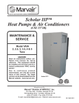
1
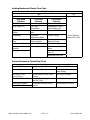
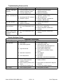
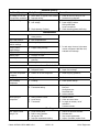
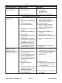
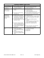
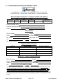
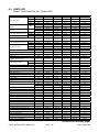
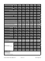
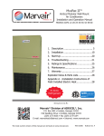
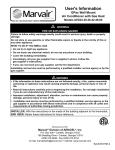
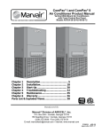
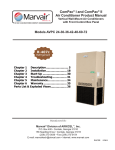
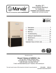
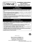
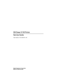
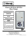
Classic HVPA & HVPSA
Heat Pumps
MAINTENANCE &
SERVICE
Models
HVPA24-30-36-42-49-60 &
HVPSA36-42-49-60
CAUTION!!
Read all instructions before use.
Retain this manual for future
reference. This equipment should
be installed and serviced only by a
trained professional HVAC service
person.
Due to continuous product
improvement, use only the current
issue of this manual. The latest
version can be downloaded from the
Marvair website - www.marvair.com.
Manufactured By:
Marvair Division of AIRXCEL®, Inc.
®
P.O. Box 400 • Cordele, Georgia 31010
156 Seedling Drive • Cordele, Georgia 31015
(229) 273-3636 • Fax (229) 273-5154
E-mail: [email protected] • Internet: www.marvair.com
Classic HVPA & HVPSA M&S 8.09-1
SECTION 15700
HEATING, VENTILATING AND AIR CONDITIONING EQUIPMENT
MAINTENANCE & SERVICE MANUAL
FOR CLASSICTM HEAT PUMP
TABLE OF CONTENTS
Chapter
1.1
Description
Page
General Description ..................................................................3
1.2
Model Identification ..................................................................4
2.1
Start-up Instructions .................................................................5
2.2
Ventilation System Calibration....................................................7
3.1
Electrical ..................................................................................9
4.1
Maintenance ............................................................................9
5.1
Function & Description of Primary Components......................... 10
6.1
Troubleshooting......................................................................13
7.1
Filing a Service/Warranty Claim ...............................................23
8.1
Warranty Statement................................................................24
9.1
Parts List................................................................................25
Classic HVPA & HVPSA M&S 8.09-1
15700 - 2
HVAC Equipment
SECTION 15700
HEATING, VENTILATING AND AIR CONDITIONING EQUIPMENT
The purpose of this manual is to provide instructions for maintenance and service for the
Marvair® Classic™ series of heat pumps. In addition to this manual, there are other pieces of
literature available from Marvair. The Product Manual covers the installation of the unit and
various accessories and the initial start-up of the unit. An overview of the product line can be
found in the Classic Product Data Sheets. The current version of this literature can be found
and downloaded from the Marvair website at www.marvair.com.
To minimize sound levels within the classroom, certain options should be selected. These options are designated by
throughout the guideline.
1.1
GENERAL OPERATION
A. Classic™ heat pumps are designed to provide quiet comfort to the classroom.
In cooling mode, the compressor will cycle on to provide the cooling required. The
system provides cooling, dehumidification and air circulation.
In heating mode the compressor (heat pump only) will cycle on to provide the
heating required. The system provides heating and air circulation. At lower outdoor
temperatures, additional heating capacity may be provided by an optional electric
resistance heater.
Ventilation air may be provided by the manual or motorized fresh air vent, power
vent or GreenWheel® ERV. These ventilation systems operate when there is a call
for cooling or heating or independently to provide fresh air. Note that with the
manual, motorized fresh air vent and the power vent options, if the compressor is
not operating and the indoor blower is running, unconditioned outside air is being
introduced into the classroom. The GreenWheel ERV provides tempered outside air.
Control systems are either a remote external thermostat, internal thermostat, or a
direct digital control interfacing with the building automation system (BAS).
Hot Gas Reheat (HGR) Dehumidification (Option). To provide on demand
dehumidification, the Classic™ heat pump can have a factory installed hot gas reheat
coil to allow dehumidification through continued cooling with discharge air reheated
to avoid over cooling the classroom. The operation of the HGR is controlled by a
three-way heat reclaim valve. The HGR coil is sized to provide a heating capacity
approximately equal to the sensible capacity of the unit When the demand for
cooling is satisfied and the humidity controller calls for dehumidification, hot gas is
directed to a reheat coil downstream from the evaporator coil to add heat to the
dehumidified, chilled air supplied to the classroom. Hot gas reheat is available with
motorized fresh air, PowerVent and GreenWheel® ventilation systems.
Marvair® recommends that for optimum performance, hot gas reheat be used in
conjunction with the GreenWheel® heat recovery ventilator. When used with other
ventilation options, hot gas reheat may not maintain satisfactory control of the
humidity in the classroom over all outdoor conditions.
Classic HVPA & HVPSA M&S 8.09-1
15700 - 3
HVAC Equipment
1.2
MODEL IDENTIFICATION
The ClassicTM heat pump identification numbering system is shown below. The model
identification number is on the data label. The data label is at the bottom of the of left
side panel.
IMPORTANT
WHEN CLASSIC SYSTEMS ARE INSTALLED, MODEL NUMBER AND SERIAL
NUMBERS ARE TO BE RECORDED AND MAINTAINED IN A LOCATION FOR
IMMEDIATE ACCESS WHEN REQUESTING FURTHER INFORMATION.
Classic HVPA & HVPSA M&S 8.09-1
15700 - 4
HVAC Equipment
2.1
START-UP PROCEDURE
Important: If your unit has a crankcase heater be sure that the crankcase heater has been
energized for at least 24 hours prior to start-up of the unit. Double check all electrical connections before applying power. Various thermostats can be used to control the heat pump.
The thermostat may have a fan switch with an Automatic and On positions, a system switch
with Heat, Cool, and Off positions, and an emergency heat position with lights. The spec
sheets have detailed description of the various Marvair® thermostats. Since other thermostats or remote control systems may be used, the following procedures should be viewed as
guidelines for standard thermostats with system and fan switches.
Check-out of Cooling Cycle
Procedure:
Classic™ Heat Pump
1. Set the fan switch to "Auto" and the system switch to "Off".
2. Move the cooling temperature on the wall thermostat to a point higher than the
room temperature. Move the heating temperature to a temperature that is lower
than the room temperature.
3. Set the thermostats system switch to "Cool" or "Auto" position. Nothing should
operate at this time.
4. Set the time delay in the control box to three minutes. Note that time delay is an
option on some Classic™ units and may not be on your heat pump.
5. Remove the cover plate from the thermostat. Slowly lower the thermostat cooling
temperature. Once the indoor fan turns on, allow approximately three minutes for
the compressor and outdoor fan to start.
For units equipped with the low ambient control, note that the outdoor fan may not
come on immediately, because it is cycled by refrigerant pressures. Some units have
a time delay module which prevents the compressor from restarting immediately
after interruption of power. See section 1.5P and 1.5Q for details on the operation of
the low ambient control and the time delay.
If the unit fails to operate, refer to the troubleshooting information in Chapter 6.1.
Classic™ Heat Pump with Economizer
1. Set the fan switch to "Auto" and the system switch to "Off".
2. Set the cooling temperature on the wall thermostat to a point higher than the room
temperature. Set the heating temperature to a temperature that is lower than room
temperature.
3. Set the thermostat system switch in the "Auto" or "Cool" position. Nothing should
operate at this time.
Classic HVPA & HVPSA M&S 8.09-1
15700 - 5
HVAC Equipment
4. Set the time delay in the Classic™ Heat Pump with Economizer control box to
3 minutes. Check the enthalpy changeover setting of the H205A or dry bulb sensor,
and reset it if needed. Refer to the Owner’s manual for instructions on setting the
H205A or dry bulb sensor.
5. Slowly lower the thermostat’s cooling temperature. The indoor fan should operate.
Once the indoor fan comes on, allow approximately three minutes for the compressor
to start. Note that the outdoor fan may not come on immediately because it is
cycled by refrigerant pressures
Note: To check the system operation under different ambient conditions, the air
temperature and enthalpy sensors must be "tricked". When outdoor ambient
conditions are higher than the control setting, a component aerosol cooler may be
sprayed directly into the enthalpy sensor to simulate low enthalpy conditions, causing
the economizer damper to open.
Alternately, when outdoor conditions are lower than the set point, a source of heat
such as a hair dryer can be directed on the air temperature sensor to simulate warmer
conditions, which will bring on mechanical cooling and start the compressor.
If the unit fails to operate, refer to the troubleshooting information in Chapter 6.1.
Check-Out of Heating Cycle
Procedure:
1. Place the thermostat system switch to "Auto" or "Heat" and the fan to "Auto".
2. Raise the heating temperature to a setting which is higher than the room
temperature. The fan and compressor should cycle on after time delay (standard on
Classic™ heat pump with economizer and all HVP models, option on all other Classic
units) has cycled.
3. Move the system switch to the "Off" position. All functions should stop.
The Blower Timed Delay Relay (BTR) keeps the blower running for 90 seconds after
the unit shuts off.
Note: The damper blade should remain closed during the heating cycle (unless the
minimum position potentiometer has been set for constant ventilation).
Classic HVPA & HVPSA M&S 8.09-1
15700 - 6
HVAC Equipment
2.2
VENTILATION SYSTEM CALIBRATION
Manual Fresh Air System (Configuration N). This is the standard ventilation
system in the Classic™ heat pump. Fresh air ventilation by means of a damper can
provide up to 15% of rated air flow of outside air. The damper has four positions
corresponding to 0, 5, 10 and 15% of rated air flow of outside air.
The damper only opens when the indoor fan is operating. Position the screw on the
side of the damper hood for the desired air flow.
Manual Damper - 0 to 450 cfm of Outside Air, No Pressure Relief
(Configuration Y). The amount of fresh air is determined by the position of the
collar on the rod. To determine the desired quantity of fresh air:
a.
With the indoor blower on, measure the quantity of supply air being discharged
into the room with a balometer.
b.
Now measure the quantity of the return air from the room. Subtract the return
air from the supply air. The difference is the amount of fresh air.
c.
Loosen the set screw that holds the collar onto the rod connected to the damper.
Move the collar and tighten the set screw.
Figure 1. Damper Adjustment
Rod
Set Screw
d.
Repeat steps a, b and c until the desired amount of fresh air is being introduced
into the room.
Important Note: Since Configuration Y does not have internal pressure relief,
the fresh air must have a passage to the outside. If a passage is not available, the
desired quantity of fresh air cannot be introduced into the room.
Motorized Damper - 0 to 450 cfm of Outside Air and Pressure Relief
(Configuration B) and the Manual Damper with Pressure Relief
(Configuration Z). The settings of the damper require a balometer and a
thermometer for measuring internal and external temperatures.
a.
Measure the total supply air with a balometer. If the supply air is controlled by
a manual fan speed controller, make certain that the air flow is in accordance
Classic HVPA & HVPSA M&S 8.09-1
15700 - 7
HVAC Equipment
with the air flow ((CFM) at various static pressures chart. This chart can be found
in the Classic Product Data Sheet or the Installation Manual. This CFM is referred to
as "C" in the illustration and equation below.
Figure 2. Damper Air Path
b.
"A" is the quantity of outside air expressed as a percentage of "C". For example,
if the supply air is 1,220 CFM and 300 CFM of outside air is required, "A" is 25%
(300 CFM/1,220 CFM).
Measure the temperature of the outside air.
Multiply the temperature by "A".
c.
"B" is the quantity of return air expressed as a percentage of "C". "A" and "B"
must equal 100%.
Measure the temperature of the indoor return air.
Multiply the temperature of the indoor air by "B".
d.
Calculate what the Tmix should be with the desired quantity of outside air.
Measure the actual temperature of Tmix at the inlet to the supply air blower or at
the inlet of the supply air blower.
Adjust the damper blade until the measured value of the Tmix equals the
calculated or desired value of Tmix.
The motorized damper, Configuration B, can be controlled by an optional relay
that allows additional external control with a choice of 24, 120 or 240V coils to
regulate fresh air ventilation in response to a control located remote from the
Classic™ heat pump.
9. Electrical Supply:
The power supply must have the appropriate voltage, phase, and ampacity for the
Classic HVPA & HVPSA M&S 8.09-1
15700 - 8
HVAC Equipment
model selected. Voltage must be maintained above minimum specified values listed
below. Refer to the unit data plate for ampacity requirements.
Table 1.
Voltage Limitations
Electrical Rating Designations*
A
C
D
Nominal Voltage
208/230
208/230
460
Phase
1
3
3
Minimum Voltage
197
197
414
Maximum Voltage
253
253
506
* Letters refer to model number code designations.
3.1
ELECTRICAL
Classic heat pumps and air conditioners are built in a wide variety of configurations and options. The illustrations of the control center and the electrical schematics shown here are typical,
but probably are not identical to your units. Please refer to the electrical schematic in each unit
for the specific construction of that unit.
4.1 MAINTENANCE
Marvair® strongly recommends that the heat pump be serviced a minimum of twice a
year – once prior to the heating season and once prior to the cooling season. At this
time the filters, evaporator coil, condenser coil, the cabinet, and condensate drains
should be serviced as described below. Also at this time, the heat pump should be
operated in the cooling and heating cycles as described in Chapter 3, Start-Up. In
addition to this seasonal check-out, the unit should be maintained as follows:
Air Filter
Replace the air filter whenever it is visibly dirty.
Indoor Coil
If the coil becomes clogged or dirty, it may be cleaned by careful vacuuming or with
a commercial evaporator cleaning spray. DO NOT use a solvent containing bleach,
acetone, or flammable substances. Turn power OFF before cleaning. Be careful
not to wet any of the electrical components. Be sure the unit has dried before
restarting.
Outdoor Coil
Periodically inspect the outdoor coil and the cabinet air reliefs for dirt or obstructions.
Remove foreign objects such as leaves, paper, etc.
If the coil is dirty, it may be washed off with a commercial solvent intended for
this purpose. TURN OFF POWER BEFORE CLEANING! Be sure that all electrical
components are thoroughly dry before restoring power.
Cabinet
The cabinet may be cleaned with a sponge and warm, soapy water or a mild
detergent. Do not use bleach, abrasive chemicals or harmful solvents.
Classic HVPA & HVPSA M&S 8.09-1
15700 - 9
HVAC Equipment
Drains
Regularly check the primary and secondary condensate drains. The secondary drain
has a stand pipe. An obstruction will force water to dump into the middle of the
unit and drain out the sides of the Classic™ Heat Pump, causing discoloration of the
side panels. If discoloration is noted, service the drains.
If a commercial drain solvent is used, flush out the drain pan and system with plenty
of fresh water to prevent corrosion.
Lubrication
Oiling of the condenser fan motor or the evaporator blower motor is not
recommended.
5.1
FUNCTION AND DESCRIPTION OF PRIMARY COMPONENTS
A. Compressor. All Classic units use a fully hermetic scroll compressor to minimize
sound levels and maximize efficiency. Scroll compressors, like several other types
of compressors, will only compress in one rotational direction. The direction of
rotation is not an issue with single-phase compressors since they will always start
and run in the proper direction. However, three phase compressors will rotate in
either direction depending upon phasing of power. Since there is a 50-50 chance
of connecting power in such a way as to cause rotation in the reverse direction, it
is imperative to confirm that the compressor is rotating in the proper direction at
the initial field start-up of the system. Verification of proper rotation is made by
observing that the suction pressure drops and the discharge pressure rises when
the compressor is energized. An alternate method of verification for self contained
system with small critical refrigerant charges, where the installation of gauges may
be objectionable, can be made by monitoring the temperature of the refrigerant
lines at the compressor. The temperature should rise on the discharge line while the
suction line temperature decreases. Reverse rotation also results in a substantially
reduced current draw when compared to tabulated values.
There is no negative impact on durability caused by operating three phase
compressors in the reversed direction for a short duration of time, usually defined
as less than one hour. However, after several minutes of operation the compressor's
internal protector will trip. The compressor will then cycle on the protector until
the phasing is corrected. Reverse operation for longer than one hour may have a
negative impact on the bearings.
B. Indoor Blower and Motor. The indoor blower assembly is an electronically
commutated blower motor and dual blowers.
C. Outdoor Air Mover. The outdoor air mover is an axial fan with an asynchronous
external rotor motor.
D. Indoor/Outdoor Coils. The coils are constructed of lanced, aluminum fins
mechanically bonded to rifled, seamless copper tubes.
E. Filter Drier - The filter drier performs two functions in the refrigerant circuit. First,
Classic HVPA & HVPSA M&S 8.09-1
15700 - 10
HVAC Equipment
it removes foreign particulate matter, e.g. dirt, scale, solder particles from the
refrigerant to protect the compressor and other components in the refrigerant system
with small openings or close tolerances. Second, it absorbs any moisture in the
refrigerant with desiccant granules.
F.
High Pressure Switch and Loss of Charge Switch. These switches render the
compressor and outdoor fan motor inoperative whenever the limits of the high or
loss of charge switches are exceeded. In the event of high pressure, the ClassicTM
unit will turn off and lockout. The high pressure switch opens at 610 psig and resets
at 420 psig.
The Loss of Charge Switch is designed to guard against the operation of the system
in the event of a loss of refrigerant. The loss of charge switch opens at 40 psig and
closes at 60 psig.
In cold weather the pressure in the refrigerant system is low prior to operation. When
the Classic™ unit starts in the heat pump mode during cold weather, low pressure
could cause the system to lock out. To guard against nuisance lockouts, the Classic
unit will not shut off if the Loss of Charge Switch (LPS) comes on during the first
eight minutes of operation. In other words, the compressor will start and operate for
eight minutes even with the LPS switch off.
The high and low pressure switches are resettable at the wall thermostat or by
turning power off and then on to the ClassicTM unit.
G. Metering Devices. The Classic uses a thermal expansion valve on the indoor
(cooling) circuit and a fixed orifice on the outdoor (heating) circuit.
H. Reversing Valve. The reversing valve reverses the refrigerant’s direction of flow in a heat
pump, allowing the heat pump to switch from cooling to heating or heating to cooling.
I.
Exhaust Air Ventilation Blower is used to exhaust classroom in the GreenWheel
ERV ventilation option. The blower can exhaust up to 450 CFM of air from the
classroom. In the standard configuration, both the exhaust and the intake ventilation
blowers are controlled by a single speed controller. This speed controller permits
the motor speed to be adjusted for the correct cfm of ventilation air. As an option,
a second motor controller may be factory installed to allow independent control of
the intake and exhaust air blowers. This allows pressurization of the classroom. All
ventilation options have an intake air blower.
J.
Intake Ventilation Air Blower (GreenWheel ERV only) is used to introduce
outside air into the classroom.
K. Electric Resistance Heat. The heaters are available in various sizes (kW) for
operation on 208/230v. 1Ø, 208/230 v. 3Ø, and 460v, 3Ø. The model number of the
heat pump indicates the power supply and kW.
L. Electric Resistance Heat Controls. Included with the electric heat assembly are
temperature switches designed to turn power off to the heaters if the temperature
is too high. There are two types of temperature switches. The first is an auto-reset
type that turns power off to the heater if it senses a temperature of 145°F. When
the temperature drops to approximately 105°F, power is restored to the heaters. This
auto-reset switch is in the low voltage circuit.
Classic HVPA & HVPSA M&S 8.09-1
15700 - 11
HVAC Equipment
The second type of switch is a one time limit switch. If it senses a temperature of
300ºF, power is turned off to the elements. This switch does NOT reset when the
temperature drops and must be replaced when it activates.
The number and location of both switches is determined by the power supply and the
kW of the heaters.
M. Ventilation Blower Fan Speed Control. Factory setting for the indoor blower
speed is full speed. If a lower speed setting is required, the blower motor speed
control may be adjusted with a slotted screwdriver rotating the speed control as
shown in Figure 3. Reference unit label for minimum required air flow settings for
specific unit model.
Figure 3. Ventilation Blower Speed Control Adjustment Instructions
SERIES 706
VARI-SPEED
MOTOR CONTROL
LO
HI
N. Standard Ventilation Control. The GreenWheel® ERV ventilation option is
equipped with a fresh air fan speed control. The fresh air fan speed control
operates both the ventilation intake and exhaust blowers together.
The GreenWheel® ERV ventilation option can be equipped with an exhaust fan air
speed control, which controls the ventilation exhaust blower independently of the
fresh air intake blower.
Demand Control Ventilation. A field or factory installed carbon dioxide sensor
controls the ventilation damper and only opens the damper when CO2 levels exceed
a specified level. Demand control ventilation saves energy and utility costs by
ventilating the classroom based upon occupancy.
Note: Not available on manual fresh air damper (“B”) configuration.
O. Outdoor Thermostat. Factory set at 40°F, this thermostat determines the outdoor
temperature at which the supplemental electric heat turns on. This may be field
adjusted to the desired temperature setting by rotating the adjustment knob.
P.
Low Ambient Control (Standard on units with economizers, optional on all other
units.) The low ambient control permits mechanical cooling when outdoor ambient
temperatures are low. The control uses a reverse-acting high pressure switch to cycle
the condenser fan motor according to liquid refrigerant pressure conditions. Switch
closure and fan operation occurs when the pressure reaches 400 PSIG. The switch
opens again when the refrigerant pressure falls to 245 PSIG. Therefore, the outdoor
Classic HVPA & HVPSA M&S 8.09-1
15700 - 12
HVAC Equipment
fan always starts after the compressor, and it will cycle frequently during normal
operation at low outdoor conditions.
Q. Compressor Time Delay. The time delay module (delay on make) prevents the
compressor from restarting immediately after interruption of power. The delay
interval, which is adjustable from .2 to 8 minutes, protects the compressor by
allowing internal refrigerant pressures to equalize. The time delay does not effect the
electric heat circuit.
6.1
TROUBLESHOOTING
In diagnosing common faults in the heat pump system, develop a logical thought
pattern as used by experienced technicians. The charts which follow are not intended
to be an answer to all problems but only to guide the technician’s thinking. Through
a series of yes and no answers, follow the logical path to a likely conclusion.
A novice technician should use these charts like a road map. Remember that the
chart should clarify a logical path to the problem’s solutions.
Electrical Checks Flow Chart
Unit Running?
NO
Thermostat Problem?
YES - Repair and Recheck
YES
NO
Transformer Problem?
NO
YES - Repair and Recheck
Voltage on Compressor Side of Contactor?
YES
NO
Run Capacitor
Voltage on Line Side of Contactor?
NO
Compressor Internal
YES
Overload Open
Compressor Winding Circuit Breakers or
Compressor Contactor
Open
Fuses Open
High Pressure Cut-Out
Unit Wiring and
YES
Connections
Low Pressure Cut-Out
Compressor Winding
Grounded
Compressor Time
Outdoor Fan Motor
Grounded
Delay
Grounded Capacitor
Unit Wiring and
Connections
Replace Fuses or
Reset Breakers and
Recheck System
Classic HVPA & HVPSA M&S 8.09-1
15700 - 13
Go to Mechanical Check
for Cooling or Heating
HVAC Equipment
Cooling Mechanical Checks Flow Chart
Unit Running?
High Head
Pressure
Dirty Outdoor Filter
Inoperative Outdoor
Fan
Overcharge
Recirculation of
Outdoor Air
Non-condensibles
Higher than Ambient
Air Entering Outdoor
Coil
Wrong Outdoor Fan
Rotation
YES
Pressure Problems?
Low Head
Pressure
Low on Charge
Low Ambient
Temperature
Inoperative
Compressor Valves
Outdoor Check Valve
Closed
Restricted Indoor
Metering Device
Restricted Filter
Drier
Reversing Valve
Failure
NO
Low Suction
Pressure
Dirty Filters
Dirty Indoor Coil
Inadequate Indoor Air
Flow
Inoperative Indoor
Blower
Low on Charge
Restricted Indoor
Metering Device
Go to Electrical
Checks Flow Chart
Restriction in System
Recirculation of
Indoor Air
Wrong Indoor
Blower Rotation
Inadequate Ducts
Outdoor Check
Valve Closed
Restricted Filter Drier
Classic HVPA & HVPSA M&S 8.09-1
15700 - 14
HVAC Equipment
Heating Mechanical Checks Flow Chart
Unit Running?
High Head
Pressure
Dirty Filters
Dirty Indoor Coil
Inoperative Indoor
Blower
Overcharge
Inadequate Indoor Air
Flow
Non-condensibles
Wrong Indoor Blower
Rotation
Inadequate Ducts
YES
Pressure Problems?
Low Head
Pressure
Low on Charge
Low Indoor
Temperature
Closed Indoor Check
Valve
Inoperative
Compressor Valves
Restricted Outdoor
Metering Device
Restricted Filter Drier
Reversing Valve Failure
NO
Low Suction
Pressure
Dirty Outdoor Coil
Inadequate Air Flow
Over Outdoor Coil
Inoperative OD Fan
Low on Charge
Go to Electrical
Checks Flow Chart
Restricted Outdoor
Metering Device
Restriction in System
Closed Indoor Check
Valve
Recirculation of Outdoor Air
Restricted Filter Drier
Defrost Mechanical Checks Flow Chart
No Defrost
Defrost System
Incomplete Defrost
Reversing Valve Stuck
Poor Sensor Location
No Defrost Timer
Control Power
Failed Defrost Control
Wrong Defrost Control Timer
Setting
Failed Defrost Relay (doesn’t
stop O.D. Fan)
Thermostat Satisfies During
Defrost
Failed Defrost Relay
Loose Default Sensor
Classic HVPA & HVPSA M&S 8.09-1
15700 - 15
Excessive Defrost
Wrong Defrost Control
Timer Setting
Poor Sensor Location
Low System Charge
Wind Affecting in Defrost
HVAC Equipment
Subcooling Calculation
1. Measure the liquid pressure at the liquid line service valve.
2. Convert the liquid line pressure to saturated temperature. See tables below.
3. Measure the liquid line temperature at the liquid line service valve.
4. Compare the liquid line temperature to the saturated temperature.
5. The difference between saturated temperature and liquid line temperature is the
subcooling. Subcooling normal range 12° to 20°.
Superheat Calculation
1. Measure the suction pressure at the suction line service valve.
2. Convert the suction line pressure to saturated temperature. See tables below.
3. Measure the suction line temperature approximately 6” to 8” from the compressor.
4. Compare the suction line temperature to the saturated temperature.
5. The difference between saturated temperature and suction line temperature is the
superheat. Superheat normal range 12° to 18°
Temperature Pressure Chart
Temp.
(°F)
-40
-35
-30
-25
-20
-15
-10
-5
0
5
10
15
20
R-22
PSIG
0.5
2.6
4.9
7.4
10.1
13.2
16.5
20.0
23.9
28.2
32.8
37.7
43.0
R-410A
PSIG
11.0
14.2
17.8
21.8
26.1
30.8
35.9
41.5
47.5
54.1
61.2
68.8
77.1
Classic HVPA & HVPSA M&S 8.09-1
Temp.
(°F)
25
30
35
40
45
50
55
60
65
70
75
80
85
R-22
PSIG
48.7
54.9
61.5
68.5
76.0
84.0
92.5
101.6
111.2
121.4
132.2
143.6
155.7
15700 - 16
R-410A
PSIG
86.0
95.5
105.7
116.6
128.3
140.8
154.1
168.2
183.2
199.2
216.1
234.0
253.0
Temp.
(°F)
90
95
100
105
110
115
120
125
130
135
140
145
150
R-22
PSIG
168.4
181.8
195.9
210.7
226.3
242.7
259.9
277.9
296.8
316.5
337.2
258.8
381.5
R-410A
PSIG
273.0
294.1
316.4
339.9
364.6
390.5
417.7
446.3
476.3
507.6
540.5
574.8
610.6
HVAC Equipment
Troubleshooting Chart
WARNING
DISCONNECT ALL POWER TO UNIT BEFORE SERVICING. CONTACTOR
MAY BREAK ONLY ONE SIDE. FAILURE TO SHUT OFF POWER CAN
CAUSE ELECTRICAL SHOCK RESULTING IN PERSONAL INJURY OR DEATH.
Problem/Symptom
Unit will not run.
Likely Cause(s)
1. Power off or loose electrical
connection.
2. Thermostat out of calibration
Correction
1. Check for correct voltage at unit disconnect. Check for correct voltage at contactor in unit.
2. Reset.
- set too high.
Outdoor fan runs,
compressor doesn’t.
3. Defective contactor.
3. Check for 24 volts at contactor coil -
4.
5.
6.
7.
1.
2.
4.
5.
6.
7.
1.
2.
Blown fuse/tripped breaker.
Transformer defective.
High pressure control open.
Low pressure control open.
Run capacitor defective
Loose connection.
or open motor winding, open
internal overload.
4. Low voltage condition.
Replace.
Check for correct voltage at compressor
- check and tighten all connections.
3. Wait at least 2 hours for overload to
reset. If still open, replace the
compressor.
4. Add start kit components.
1. Improperly sized unit.
2. Improper indoor air flow.
1. Recalculate load.
2. Check - should be approximately 400 CFM
3. Incorrect refrigerant charge.
4. Air, non-condensibles or mois-
3. Charge per procedure.
4. Recover refrigerant, evacuate and
3. Compressor stuck, grounded
Insufficient cooling.
replace if contacts are open.
Replace fuses/reset breaker.
Check wiring - replace transformer.
Reset.
Reset.
per ton.
ture in system.
recharge, add filter drier.
Compressor short cycles. 1. Incorrect voltage.
Registers sweat.
1. At compressor terminals, voltage must be
2. Defective overload protector.
3. Refrigerant undercharging.
1. Low indoor air flow.
±10% of nameplate marking when unit is
operating.
2. Replace - check for correct voltage.
3. Add refrigerant.
1. Increase speed of blower or reduce
restriction - replace air filter.
High head - low vapor
pressures.
High head - high or
normal vapor
pressures - cooling
mode.
1. Restriction in liquid line, expansion device or filter drier.
2. Flow check piston size too small.
3. Incorrect capillary tubes.
1.
2.
3.
4.
Dirty outdoor coil.
Refrigerant overcharge.
Outdoor fan not running.
Air or non-condensibles in
system.
Classic HVPA & HVPSA M&S 8.09-1
15700 - 17
1. Remove or replace defective
2.
3.
1.
2.
3.
4.
component.
Change to correct size piston.
Change assembly coil.
Clean coil.
Correct system charge.
Repair or replace.
Recover refrigerant, evacuate and
recharge.
HVAC Equipment
Troubleshooting Chart (cont’d)
Problem/Symptom
Low head - high vapor
pressures.
Low vapor - cool compressor - iced indoor coil.
Likely Cause(s)
1. Flow check piston size too large.
2. Defective compressor valves.
3. Incorrect capillary tubes.
1. Low indoor air flow.
2. Operating below 55°F outdoors.
3. Moisture in system.
High vapor pressure.
Fluctuating head and
vapor pressures..
1.
2.
1.
2.
Excessive load.
Defective compressor.
TXV hunting.
Air or non-condensibles in system.
Correction
1. Change to correct size piston.
Replace compressor.
2. Replace coil assembly.
1. Increase speed of blower or reduce
restriction - replace air filter.
2. Add low ambient kit.
3. Recover refrigerant - evacuate and
recharge - add filter drier.
1. Recheck load calculation.
2. Replace.
1. Check TXV bulb clamp - check air distribution on coil - replace TXV.
2. Recover refrigerant, evacuate and
recharge.
Gurgle or pulsing noise
at expansion device or
liquid line.
1. Air or non-condensibles in system.
1. Recover refrigerant, evacuate and
recharge.
Service Analyzer Charts
Problem/Symptom
High superheat.
Compressor Overheating
Correction
Likely Cause(s)
1. Low charge.
1. Check system charge.
2. Faulty metering device.
2. Restricted cap tube, TXV.
3. High internal load.
4. Restriction in liquid line.
5. Low head pressure.
Low voltage.
1. Loose wire connections.
2. Dirty or pitted compressor
Power element superheat adjustment.
Foreign matter stopping flow.
3. Hot air (attic) entering room.
Heat source on; miswired or faulty
control.
4. Drier plugged.
Line kinked.
5. Low charge.
Operating in low ambient temperatures.
1. Check wiring.
2. Replace contactor.
contactor contacts.
3. Power company problem, transformer.
High voltage.
continues.
4. Undersized wire feeding unit.
1. Power company problem.
Classic HVPA & HVPSA M&S 8.09-1
3. Have problem corrected before diagnosis
15700 - 18
4. Correct and complete diagnosis.
1. Have problem corrected.
HVAC Equipment
Problem/Symptom
High head pressure.
Compressor Overheating (cont’d)
Correction
Likely Cause(s)
1. Overcharge.
1. Check system charge.
2. Dirty heat pump coil.
2. Clean coil.
3. Faulty or wrong size heat pump
3. Replace fan motor.
fan motor.
4. Faulty outdoor blower.
5. Recirculation of air.
6. Additional heat source.
7. Non-condensibles
4. Replace blower.
Replace with correct rotation motor.
5. Correct installation.
6. Check for recirculating from other equipment.
7. Recover refrigerant, evacuate and
recharge system.
Short cycling of
compressor.
Faulty compressor
valves.
1. Faulty pressure control.
2. Loose wiring.
3. Thermostat.
1. Replace pressure control.
2. Check unit wiring.
3. Located in supply air stream.
Differential setting too close.
Customer mis-use.
Internal foreign matter.
Power element failure.
Valve too small.
Distributor tube/tubes restricted.
Restricted with foreign matter.
Kinked.
I.D. reduced from previous compressor
failure.
Check system charge.
Dirty coil.
Dirty filter.
Duct too small or restricted.
Replace.
Replace compressor.
4. TXV.
4.
5. Capillary Tube.
5.
6. Low charge.
7. Low evaporator air flow.
6.
7.
8. Faulty run capacitor.
9. Faulty internal overload.
1. Fast equalization/low pressure
8.
9.
1. Replace compressor and examine system
to locate reason.
difference.
Electrical
Voltage present on load
side of compressor contactor and compressor
won’t run.
1. Run capacitor.
2. Internal overload.
3. Compressor windings.
1. Check with ohmmeter.
2. Allow time to reset.
3. Check for current ohms.
Voltage present on line
side of compressor
contactor only.
1. Thermostat.
1. Check for control voltage to
2. Compressor control circuit.
2. High pressure switch.
compressor-contactor coil.
Low pressure switch.
Compressor turned off/on control or
interlock.
Classic HVPA & HVPSA M&S 8.09-1
15700 - 19
HVAC Equipment
Problem/Symptom
No voltage on line side
of compressor contactor.
Improper voltage.
Moisture.
Electrical (cont’d)
Likely Cause(s)
1. Blown fuses or tripped circuit breaker.
2. Improper wiring.
1. High voltage.
2. Low voltage.
3. Single phasing (3 phase).
Contamination
1. Poor evacuation on installation or
Correction
1. Check for short in wiring or unit.
2. Recheck wiring diagram.
1. Power supply problem.
2. Power supply problem.
Wiring undersized.
Loose connections.
3. Check incoming power and fusing.
during service.
High head pressure.
Unusual head and
suction readings.
1. Non-condensibles air.
1. Wrong refrigerant.
Foreign matter copper fittings.
1. Copper tubing cuttings.
Copper oxide.
1. Dirty copper piping.
1. Nitrogen not used.
1. Adding flux before seating copper
Welding scale.
Soldering flux.
1. In each case, the cure is the same,
recover refrigerant. Add filter drier,
evacuate and recharge.
part way.
Excess soft solder.
Low suction pressure.
Cold, noisy compressor
- slugging.
Noisy compressor.
Cold, sweating
compressor.
Low load.
Short cycling of
compressor.
1. Wrong solder material.
Loss of Lubrication
1. Low charge.
1. Check system charge.
2. Refrigerant leaks.
2. Repair and recharge.
1. Dilution of oil with refrigerant.
1. Observe piping guidelines.
1. Migration.
1. Flooding.
1. Check crankcase heater.
1. Check system charge.
1. Reduced air flow.
2. Thermostat setting.
1. Dirty filter.
1. Faulty pressure control.
2. Loose wiring.
3. Thermostat.
1. Replace control.
2. Check all control wires.
3. In supply air stream, out of
Dirty coil.
Wrong duct size.
Restricted duct.
2. Advise customer.
calibration.
Customer misuse.
Flooding
Poor system control
using a TXV.
1.
2.
3.
4.
Loose sensing bulb.
Bulb in wrong position.
Wrong size TXV.
Improper superheater setting.
Classic HVPA & HVPSA M&S 8.09-1
15700 - 20
1.
2.
3.
4.
Secure the bulb and insulate.
Relocate bulb.
Use correct replacement.
Adjust, if possible, replace if not.
HVAC Equipment
Problem/Symptom
Poor system control
using capillary tubes.
Flooding (cont’d)
Likely Cause(s)
1. Overcharge.
2. High head pressures.
Correction
1. Check system charge.
2. Dirty heat pump.
Restricted air flow.
Recirculation of air.
3. Adjust air flow to 400 CFM/Ton.
High superheat, low
suction pressure.
3. Evaporator air flow too low.
Thermostatic Expansion Valves
1. Moisture freezing and blocking
1. Recover charge, install filter drier,
evacuate system, recharge.
valve.
2. Dirt or foreign material blocking
2. Recover charge, install filter-drier,
evacuate system, recharge.
valve.
3. Low refrigerant charge.
4. Vapor bubbles in liquid line.
3. Correct the charge.
4. Remove restriction in liquid line.
5. Misapplication of internally equal-
Correct the refrigerant charge.
Remove non-condensible gases.
5. Use correct TXV.
ized valve.
6. Plugged external equalizer line.
6. Remove external equalizer line
7. Undersized TXV.
8. Loss of charge from power head
7. Replace with correct valve.
8. Replace power head or complete TXV.
restriction.
sensing bulb.
9. Charge migration from sensing
bulb to power head (warm power
head with warm, wet cloth. Does
valve operate correctly now?)
10. Improper superheat adjustment
(only applicable to TXV with adjustable superheat settings).
Valve feeds too much
refrigerant, with low
superheat and higher than
normal suction pressure.
1. Moisture causing valve to stick
2.
3.
4.
5.
open.
Dirt or foreign material causing
valve to stick open.
TXV seat leak (a gurgling or hissing sound is heard at the TXV
during the off cycle, if this is the
cause). Not applicable to bleed
port valves.
Oversized TXV.
Incorrect sensing bulb
location.
6. Low superheat adjustment (only
applicable to TXV with adjustable superheat setting).
7. Incorrectly installed or restricted
external equalizer line.
Classic HVPA & HVPSA M&S 8.09-1
15700 - 21
9. Ensure TXV is warmer than sensing
bulb.
10. Adjust superheat setting counterclockwise.
1. Recover refrigerant, replace filter drier,
evacuate system and then recharge.
2. Recover refrigerant, replace filter drier,
evacuate system and recharge.
3. Replace the TXV.
4. Install correct TXV.
5. Install bulb with two mounting straps,
in 2:00 or 4:00 position on suction
line, with insulation.
6. Turn superheat adjustment clockwise.
7. Remove restriction, or relocate external equalizer.
HVAC Equipment
Problem/Symptom
Compressor flood back
upon start-up.
Superheat is low to
normal with low
suction pressure.
Thermostatic Expansion Valves (cont’d)
Correction
Likely Cause(s)
1. Any of the causes listed under
1. Any of the solutions listed under
symptoms of problem 2.
1. Unequal evaporator circuit
loading.
2. Low load or air flow entering
evaporator coil.
solutions of problem 2.
1. Ensure air flow is equally distributed
through evaporator.
Ensure proper piston.
Check for blocked distributor tubes.
2. Ensure blower is moving proper air CFM.
Remove/correct any air flow restriction.
Superheat and
suction pressure
fluctuate (valve is
hunting)
1. Expansion valve is oversized.
2. Sensing bulb is affected by liq-
1. Install correct TXV.
2. Relocate sensing bulb in another position
Valve does not regulate
at all.
1. External equalizer line not con-
1. Connect equalizer line in proper location,
nected or line plugged in.
2. Sensing bulb lost its operating
charge.
3. Valve body damaged during
soldering or by improper installation.
or remove any blockage.
2. Replace TXV.
3. Replace TXV.
around the circumference of the suction
uid refrigerant or refrigerant oil
flowing through suction line.
line.
3. Unequal refrigerant flow through 3. Ensure proper distributor piston is
evaporator circuits.
inserted.
Ensure sensing bulb is located properly.
Check for block distributor tubes.
4. Improper superheat adjust4. Replace TXV or adjust superheat.
ment (only possible with TXV
having superheat adjustment.
5. Moisture freezing and partially
5. Recover refrigerant, change filter drier,
blocking TXV.
evacuate system and recharge.
Classic HVPA & HVPSA M&S 8.09-1
15700 - 22
HVAC Equipment
7.1
PROCEDURE FOR FILING A WARRANTY CLAIM
156 Seedling Drive • Cordele, GA 31015 • P.O. Box 400 • Cordele, GA 31010-0400
Phone 800-841-7854 • 229-273-3636 • Fax 229-276-1479 • Svc Pager 800-204-8210
MARVAIR SERVICE REQUEST / PURCHASE ORDER FOR SERVICE
DATE
RECEIVED
TIME
NOTIFIED
DATE
DISPATCHED
Marvair Use
TIME
DISPATCHED
Marvair Use
CUSTOMER PO#
MARVAIR
SERVICE PO #
Marvair Use
Person requesting service:
Company requesting service:
Phone #:
Fax #:
Site Information:
Point of Contact:
Company:
Phone:
Alt. Name & Phone:
Site Address:
Site# / Bldg# / Name:
City:
ST.
Zip:
Site Access Information:
Equipment Repair Information:
MODEL #
SERIAL NUMBER
NATURE OF PROBLEM
Marvair Use - Service Company Information:
Service Company:
Contact:
Phone #:
Fax:
Address:
Labor Rate:
City:
ST.
Zip:
If included here, please review and sign our service centers Warranty Policy Information/Agreement then fax back to 229-2735154. Invoices will be paid in accordance with Labor Allowance Guidelines included with this PO. Failure to follow these
guidelines and labor allowances may result in delayed payment. All over time work must be approved in advance. All times
allowed for entry into the refrigerant circuit include evacuation, recharge, refrigerant and drier change. Service centers are
required to notify Marvair if site travel will exceed 1 hour each way – additional travel time must be approved in advance.
Detailed invoices or service tech call sheet/work orders are required to be submitted with invoices for payment. Service Tech’s
should document work in detail and include/verify model(s) and serial number(s) of the equipment and include Marvair’s PO on
all documentation. Marvair will provide contractors with warranty replacement parts for service calls please contact us at 800841-7854.
Classic HVPA & HVPSA M&S 8.09-1
15700 - 23
HVAC Equipment
8.1
WARRANTY
If any part of your Marvair® Air Conditioner, Heat Pump or Unit Ventilator fails because
of a manufacturing defect within fifteen months from the date of original shipment from
Marvair or within twelve months from the date of original start-up, whichever is the
earlier date, Marvair will furnish without charge, EXW Cordele, Georgia, the required
replacement part. Any transportation, related service labor, diagnosis calls, filter,
driers, and refrigerant are not included. The owner must provide proof of the date of
the original start-up. The owner’s registration card filed with Marvair, the contractor’s
invoice, the certificate of occupancy or similar document are examples of proof of the
date of the original start-up.
In addition, if the hermetic compressor fails because of a manufacturing defect within
sixty months from the date of original shipment from Marvair®, Marvair will furnish
without charge, EXW Cordele, Georgia, the required replacement part. Any related
service labor, diagnosis calls, filter, driers and refrigerant are not included. Marvair will
pay for non-priority shipping costs of the compressor during the first twelve months
of the warranty period. After the first twelve months of the warranty period, all costs
of shipment and risk of loss during the shipment of the compressor shall be the
responsibility of the owner.
The owner of the product may ship the allegedly defective or malfunctioning product or
part to Marvair®, at such owner’s expense, and Marvair will diagnose the defect and, if
the defect is covered under this warranty, Marvair will honor its warranty and furnish the
required replacement part. All costs for shipment and risk of loss during shipment of the
product to Marvair and back to the owner shall be the responsibility and liability of the
owner. Upon written request by an owner, Marvair may arrange for remote diagnosis of
the allegedly defective or malfunctioning product or part but all costs for transportation,
lodging and related expenses with regard to such diagnostic services shall be the
responsibility and liability of the owner.
An owner requesting performance under this Warranty shall provide reasonable
access to the allegedly defective or malfunctioning product or part to Marvair® and its
authorized agents and employees.
This warranty applies only to products purchased and retained for use within the
U.S.A., Canada, and Mexico. This warranty does not cover damage caused by improper
installation, misuse of equipment or negligent servicing.
THIS WARRANTY CONSTITUTES THE EXCLUSIVE REMEDY OF ANY PURCHASER OF
A MARVAIR® HEAT PUMP OR AIR CONDITIONER AND IS IN LIEU OF ALL OTHER
WARRANTIES, EXPRESSED OR IMPLIED, INCLUDING, WITHOUT LIMITATION, ANY
IMPLIED WARRANTY OF MERCHANTABILITY OR FITNESS FOR USE, TO THE FULLEST
EXTENT PERMITTED BY LAW. IN NO EVENT SHALL ANY IMPLIED WARRANTY OF
MERCHANTABILITY OR FITNESS FOR USE EXCEED THE TERMS OF THE APPLICABLE
WARRANTY STATED ABOVE AND MARVAIR SHALL HAVE NO OTHER OBLIGATION
OR LIABILITY. IN NO EVENT SHALL MARVAIR BE LIABLE FOR INCIDENTAL OR
CONSEQUENTIAL DAMAGES OR MONETARY DAMAGES.
THIS WARRANTY GIVES YOU SPECIFIC LEGAL RIGHTS, AND YOU MAY ALSO HAVE
OTHER RIGHTS WHICH VARY FROM STATE-TO-STATE. Some states do not allow
limitations or exclusions, so the above limitations and exclusions may not apply to you.
Classic HVPA & HVPSA M&S 8.09-1
15700 - 24
HVAC Equipment
9.1
PARTS LIST
Classic™ Heat Pump Parts List - Models HVPA
PARTS
Compressor, Scroll
Capacitor, Scroll Compressor
ufd/volts
HVPA24HP
HVPA30HP
HVPA36HP
HVPA42HP
HVPA49HP
HVPA60HP
HPA1
10333 (K5)
10298
10349
10352
10310
10313
HPF2
10384
10378
10385
10388
10388
10389
HPC3
10327
10299
10350
10353
10311
10314
HPD4
10328
10300
10351
10354
10312
10315
50280
50315
50321
50321
50327
50315 (2)
35 / 370
40 / 370
45 / 370
45 / 370
70 / 440
40 / 370
50315
50323
50323
50159
50159
50320 (2)
HPA
Capacitor, Scroll Compressor
ufd/volts
HPF
40 / 370
60 / 370
60 / 370
80 / 370
80 / 370
40 / 440
HPA/HPF
19012
19012
19012
19012
19012
19012
HPC/HPD
19013
19013
19013
19013
19013
19013
Sound Blanket, Compressor
20052
20052
20052
20054
20054
20054
Indoor Coil
60385
16 x 33
60360
16 x 36
60360
16 x 36
60340
18 x 36
60027
24 x 36.5
60027
24 x 36.5
Compressor Plug/Cord, 80” Long
Thermal Expansion/Check Valve
P/N
20362
20362
20366
20366
20337
20337
Feeders
See Below
See Below
See Below
See Below
4/D209/20”
4/D209/20”
P/N
20367
20367
20367
20368
Included
Included
Feeders
20”
20”
20”
20”
20”
20”
Nozzle
J2
J2
J2
J3
E3
E3
Coil, Evaporator, Reheat (G Option5)
60051
60148
60148
60148
60133
60133
Valve, 3-Way Diverting (G Option)
20257
20257
20257
20257
20257
20257
Coil, Solenoid Valve (G Option)
20028
20028
20028
20028
20028
20028
Outdoor Coil
60380
60370
60370
60355
60072 (2)
60072 (2)
20119
2 x 3/16” x 20”
20119
2 x 3/16” x 20”
20119
2 x 3/16” x 20”
20121
4 x 3/16” x 20”
20338 (2)
6 x 3/16” x 32”
20348 (2)
6 x 3/16” x 32”
20082 (2)
Distributor Assembly
Distributor, Outdoor, Heating
P/N
20103
20097
20064
20082
20083 (Inc.)
Size
0.045
0.049
0.053
0.057
0.055
0.057
Indoor Motor, Double Shafted, 240 Volt, ECM
40087
40081
40081
40081
40090
40090
Blower, L.H.
30050
30090
30090
30090
30090
30090
Blower, R.H.
30055
30092
30092
30092
30092
30092
9-7T DD
10-8 DD
10-8 DD
10-8 DD
10-8 DD
10-8 DD
Orifice, Outdoor, Heating
Blower Wheel / Housing
Digital Control Unit
70363
70363
70363
70363
70363
70363
Cable Assembly
01511
01511
01511
01511
01511
01511
Power Cable Assembly
01512
01512
01512
01512
01512
01512
Outdoor Motor
40096
40098
40098
40098
40051
40051
1/4 1075
1/3 825
1/3 825
1/3 825
1/2 825
1/2 825
50350
50240
50240
50240
50360
50360
30115
30135
30135
30135
30149
30149
T2004-22
T2404-20
T2404-20
T2404-20
T2404-34
T2404-34
HP/RPM
Capacitor, Outdoor
Fan Blade
Reversing Valve, RV
20135B
20135B
20135B
20135B
20258A
20258A
Solenoid Coil, Reversing Valve
50225B
50225B
50225B
50225B
50225A
50225A
Filter Drier
70388
70388
70388
70388
70428
70428
High Pressure Control (610 Open, 420 Close)
70343
70343
70343
70343
70343
70343
Loss of Charge Switch (40 Open, 60 Close)
70342
70342
70342
70342
70342
70342
Accumulator (Orifice)
70320 (.040)
70330 (.040)
70330 (.040)
70330 (.040)
70340 (.055)
70340 (.055)
Defrost Control (DFC)
20173
20173
20173
20173
20173
20173
Motor, Economizer (EPA)
40101
40101
40101
40101
40101
40101
Enthalpy Control, )
70230
70230
70230
70230
70230
70230
Mixed Air Relay (MAR)
50164
50164
50164
50164
50164
50164
Mixed Air Sensor (MAS)
70229
70229
70229
70229
70229
70229
GreenWheel Blower, Flanged, 400 CFM
50780 (2)
50780 (2)
50780 (2)
50780 (2)
50780 (2)
50780 (2)
Capacitor, 4 ufd @ 370 Volts,
50256 (2)
50256 (2)
50256 (2)
50256 (2)
50256 (2)
50256 (2)
01226
01226
01226
01226
01226
01226
Motor, GreenWheel Drive
40007
40007
40007
40007
40007
40007
Capacitor, 2 ufd @ 370 Volts
50326
50326
50326
50326
50326
50326
Fan Speed Controller (230 Volt)
70049
70049
70049
70049
70049
70049
Belting, 3/16” Round Urethane
P/80390
P/80390
P/80390
P/80390
P/80390
P/80390
Energy Recovery Wheel
(continued on following page)
Classic HVPA & HVPSA M&S 8.09-1
15700 - 25
HVAC Equipment
HVPA24HP
HVPA30HP
HVPA36HP
HVPA42HP
HVPA49HP
Contactor, Compressor, 30 Amp
PARTS
HPA
50020
50020
50020
50020
n/a
n/a
Contactor, Compressor, 40 Amp
HPA
n/a
n/a
n/a
n/a
50030
50030
Contactor, Compressor, 30 Amp
HPC/HPD
50040
50040
50040
50040
50040
50040
92030
92030
92030
92030
92030
92030
Standard
50419
50419
50419
50419
50419
50419
B-Damper6
50420
50420
50420
50420
50420
50420
Actuator, Motor, B-Damper
40107
40107
40107
40107
40107
40107
Lockout Relay (LOR)
50214
50214
50214
50214
50214
50214
Clip for Low Vibration
01257
01257
01257
01257
01257
01257
Relay, Defrost (DFR)
50200
50200
50200
50200
50200
50200
Relay, Heat/Cool, DPDT, 24 Volt
50420
50420
50420
50420
50420
50420
Relay, S-Circuit (SR)
50164
50164
50164
50164
50164
50164
Control Board, Heat Pump,
Relay, Fan Blower Control (BTR)
Relay, B-Damper
HVPA60HP
Relay, Outdoor Fan Motor (OFR)
HPD
50205
50205
50205
50205
50205
50205
Relay, Heat/Blower (HBR)
HPD
50205
50205
50205
50205
50205
50205
Sensor, Open 56 F, Close 28 F
50102
50102
50102
50102
50102
50102
Resistor, 4.7K Ohm, 1/2 Watt, 5% Tolerance
50293
50293
50293
50293
50293
50293
Relay, DPST
50205
50205
50205
50205
50205
50205
Controller, PLC,
70275
70275
70275
70275
70275
70275
P/50182
P/50182
P/50182
P/50182
P/50182
P/50182
50199
50199
50199
50199
50199
50199
Transformer (460 to 230 Volts),
50147
1.5 KVA
50147
1.5 KVA
50147
1.5 KVA
50147
1.5 KVA
P/50007
2.0 KVA
P/50007
2.0 KVA
Transformer (460 to 230 Volts), GreenWheel
P/50007
2.0 KVA
P/50007
2.0 KVA
P/50007
2.0 KVA
P/50007
2.0 KVA
P/50008
3.0 KVA
P/50008
3.0 KVA
Contactor, Heat, 2 Pole, 30A (4 to 5 kW)
50020
50020
50020
50020
50020
50020
Contactor, Heat, 3 Pole, 40A (6 to 10 kW)
50030
50030
50030
50030
50030
50030
HPC/HPD
50040
50040
50040
50040
50040
50040
Heater, 4 kW, 240 Volts
HPA
70413
n/a
n/a
n/a
n/a
n/a
Heater, 5 kW, 240 Volts
HPA
70412
70412
70412
70412
70412
70412
Heater, 6 kW, 240 Volts
HPA/HPC
70444
70444
70444
70444
70444
70444
Heater, 8 kW, 240 Volts
HPA
70414
70414
70414
n/a
n/a
n/a
Heater, 9 kW, 240 Volts
HPA/HPC
70445
70445
70445
70445
70445
70445
Heater, 10 kW, 240 Volts
HPA
70411
70411
70411
70411
70411
70411
Heater, 12 kW, 240 Volts
HPA/HPC
70446
70446
70446
70446
70446
70446
Heater, 15 kW, 240 Volts
HPA/HPC
70410
70410
70410
70410
70410
70410
Heater, 6 kW, 460 Volts
HPD
70440
70440
70440
70440
70440
70440
Heater, 9 kW, 460 Volts
HPD
70441
70441
70441
70441
70441
70441
Heater, 12 kW, 460 Volts
HPD
70442
70442
70442
70442
70442
70442
Heater, 15 kW, 460 Volts
HPD
70443
70443
70443
70443
70443
70443
Dual Limit Control (145°F Open, 115°F Reset, 175°F Fail)
70006
70006
70006
70006
70006
70006
One Time Limit Control (165° F Open/Fail)
70005
70005
70005
70005
70005
70005
80136
16 x 30
80139
22 x 36.5
80139
22 x 36.5
80139
22 x 36.5
81199 (2)
18 x 24
81199 (2)
18 x 24
80138
80162
80162
80162
81257 (2)
81257 (2)
Relay, Indoor Blower (IBR)
Used with PLC
Low Voltage Transformer (50 VA)
Contactor, Heat, 3 Pole, 30A
Filter, Heavy Duty, 1” Thick
Dimensions (inches)
Filter, Pleated, 2” Thick
LAUSD Circuit Breakers
(Bold and Hi-Lighted are Standard)
MFS
HPA (2 Pole)
HPC (3 Pole)
HPD (3 Pole)
15
n/a
70128
70432
20
n/a
70170
70436
25
70127
70108
70433
30
70171
70109
70434
35
70107
70121
70438
40
70185
70177
70435
45
70179
70333
n/a
50
70113
70182
n/a
60
70178
70183
n/a
HPA=208/230v, 1ø, 60 Hz.
2
HPF=208/230v, 3ø, 50 Hz.
3
HPC=208/230v, 3ø, 60 Hz.
4
HPD=460v. 30248, 60 Hz.
5
G option, Hot Gas Reheat
6
B option= motorized fresh air damper
1
Classic HVPA & HVPSA M&S 8.09-1
15700 - 26
HVAC Equipment
Classic™ Heat Pump Parts List - Models HVPSA
PART
Compressor, Scroll
Capacitor, Scroll Compressor
ufd/volts
Compressor Plug/Cord, 80” Long
Plug, Unloader Solenoid
Comfort Alert
Comfort Alert
Sound Blanket, Compressor
Indoor Coil
Thermal Expansion/Check Valve
Distributor Assembly
Coil, Evaporator, Reheat (G Option4)
Valve, 3-Way Diverting (G Option4)
Coil, Solenoid Valve (G Option4)
Outdoor Coil
Distributor, Outdoor, Heating
Orifice, Outdoor, Heating
Indoor Motor, Double Shafted, 240 Volt, ECM
Blower, L.H.
Blower, R.H.
Blower Wheel / Housing
Digital Control Unit
Cable Assembly
Power Cable Assembly
Outdoor Motor
(HP/RPM)
Capacitor, Outdoor
Fan Blade
Filter Drier (Reversible)
High Pressure Control (610 Open, 420 Close)
Loss of Charge Switch (40 Open, 60 Close)
Accumulator (Orifice)
Defrost Control (DFC)
Reversing Valve, RV
Solenoid Coil, RV
Motor, Economizer (EPA)
Enthalpy Control, (EC)
Mixed Air Relay (MAR)
Mixed Air Sensor (MAS)
GreenWheel Blower, Flanged, 400 CFM
Capacitor, 4 ufd @ 370 Volts, Square
Energy Recovery Wheel
Motor, GreenWheel Drive
Capacitor, 2 ufd @ 370 Volts
Fan Speed Controller (230 Volt)
Belting, 3/16” Round Urethane
Contactor, Compressor, 30 Amp
Contactor, Compressor, 40 Amp
Contactor, Compressor, 30 Amp
Control Board, Heat Pump,
HPA1
HPC2
HPD3
HPA
HPA
HPC/HPD
HPA
HPC/HPD
HPA
HPA
HPC/HPD
HVPSA36HP
10334
10335
10336
50315
40 / 370
19012
19013
01554
19014
19015
20063
60360
20366
20367
60148
20257
20028
60370
20119
20064
40081
30090
30092
10-8 DD
70363
01511
01512
40098
1/3 825
50240
30135
70388
70343
70342
70330 (.040)
20173
20135B
50225B
40101
70230
50164
HVPSA42HP
10345
10346
10355
50321
45 / 370
19012
19013
01554
19014
19015
20063
60340
20366
20368
60148
20257
20028
60355
20121
20082
40081
30090
30092
10-8 DD
70363
01511
01512
40098
1/3 825
50240
30135
70388
70343
70342
70330 (.040)
20173
20135B
50225B
40101
70230
50164
HVPSA49HP
10337
10338
10339
50321
45 / 370
19012
19013
01554
19014
19015
20063
60027
20337
Included
60133
20257
20028
60072 (2)
20338 (2)
20083 (Included)
40090
30090
30092
10-8 DD
70363
01511
01512
40051
1/2 825
50360
30149
70428
70343
70342
70340 (.055)
20173
20258A
50225A
40101
70230
50164
HVPSA60HP
10340
10341
10342
50315 (Two)
40 / 370
19012
19013
01554
19014
19015
20063
60027
20337
Included
60133
20257
20028
60072 (2)
20348 (2)
20082 (2)
40090
30090
30092
10-8 DD
70363
01511
01512
40051
1/2 825
50360
30149
70428
70343
70342
70340 (.055)
20173
20258A
50225A
40101
70230
50164
70229
50780 (2)
50256 (2)
01226
40007
50326
70049
P/80390
50020
n/a
50040
92030
70229
50780 (2)
50256 (2)
01226
40007
50326
70049
P/80390
50020
n/a
50040
92030
70229
50780 (2)
50256 (2)
01226
40007
50326
70049
P/80390
n/a
50030
50040
92030
70229
50780 (2)
50256 (2)
01226
40007
50326
70049
P/80390
n/a
50030
50040
92030
(continued on following page)
Classic HVPA & HVPSA M&S 8.09-1
15700 - 27
HVAC Equipment
PART
Relay, Fan Blower Control (BTR)
Relay, B-Damper
Actuator, Motor, B-Damper
Lockout Relay (LOR)
Clip for Low Vibration
Relay, Defrost (DFR)
Relay, Heat/Cool, DPDT, 24 Volt
Relay, S-Circuit (SR)
Relay, Outdoor Fan Motor (OFR)
Relay, Heat/Blower (HBR)
Sensor, Open 56° F, Close 28° F
Resistor, 4.7K Ohm, 1/2 Watt, 5% Tolerance
Relay, DPST
Controller, PLC,
Relay, Indoor Blower (IBR) Used with PLC
Low Voltage Transformer (50 VA)
Standard
B-Damper
HPD
HPD
Transformer (460 to 230 Volts),
Transformer (460 to 230 Volts), GreenWheel ERV
Contactor, Heat, 2 Pole, 30A (4 to 5 kW)
Contactor, Heat, 3 Pole, 40A (6 to 10 kW)
Contactor, Heat, 3 Pole, 30A
Heater, 4 kW, 240 Volts
Heater, 5 kW, 240 Volts
Heater, 6 kW, 240 Volts
Heater, 8 kW, 240 Volts
Heater, 9 kW, 240 Volts
Heater, 10 kW, 240 Volts
Heater, 12 kW, 240 Volts
Heater, 15 kW, 240 Volts
Heater, 6 kW, 460 Volts
Heater, 9 kW, 460 Volts
Heater, 12 kW, 460 Volts
Heater, 15 kW, 460 Volts
Dual Limit Control (145oF Open, 115oF Reset,
One Time Limit Control (165o F Open/Fail)
Filter, Heavy Duty, 1” Thick
Filter, Pleated, 2” Thick
Circuit Breaker
1HPA=208/230v., 1ø, 60 Hz.
2 HPC=208/230v., 3ø, 60 Hz.
3 HPC=460v., 3ø, 60 Hz.
4G option = Hot Gas Reheat
Classic HVPA & HVPSA M&S 8.09-1
HPC/HPD
HPA
HPA
HPA/HPC
HPA
HPA/HPC
HPA
HPA/HPC
HPA/HPC
HPD
HPD
HPD
HPD
175oF Fail)
HVPSA36HP
50419
50420
40107
50214
01257
50200
50420
50164
50205
50205
50102
50293
50205
70275
P/50182
50199
50147
1.5 KVA
P/50007
2.0 KVA
50020
50030
50040
n/a
70412
70444
70414
70445
70411
70446
70410
70440
70441
70442
70443
70006
70005
80139
22 x 36.5
80162
70178 (HPA)
15700 - 28
HVPSA42HP
50419
50420
40107
50214
01257
50200
50420
50164
50205
50205
50102
50293
50205
70275
P/50182
50199
50147
1.5 KVA
P/50007
2.0 KVA
50020
50030
50040
n/a
70412
70444
n/a
70445
70411
70446
70410
70440
70441
70442
70443
70006
70005
80139
22 x 36.5
80162
70183 (HPC)
HVPSA49HP
50419
50420
40107
50214
01257
50200
50420
50164
50205
50205
50102
50293
50205
70275
P/50182
50199
P/50007
2.0 KVA
P/50008
3.0 KVA
50020
50030
50040
n/a
70412
70444
n/a
70445
70411
70446
70410
70440
70441
70442
70443
70006
70005
81199 (2)
18 x 24
81257 (2)
70435 (HPD)
HVPSA60HP
50419
50420
40107
50214
01257
50200
50420
50164
50205
50205
50102
50293
50205
70275
P/50182
50199
P/50007
2.0 KVA
P/50008
3.0 KVA
50020
50030
50040
n/a
70412
70444
n/a
70445
70411
70446
70410
70440
70441
70442
70443
70006
70005
81199 (2)
18 x 24
81257 (2)
HVAC Equipment