1
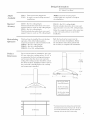
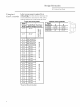
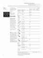
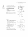
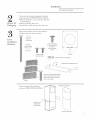
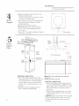
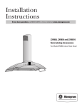
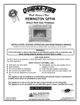
GE Monogram
®
Installation
Instructions
36" Island
Vent
Hood
Model
ZV850
Monogram°
Before you begin - Read these instructions
completely
and careflllly.
IMPORTANT
- Save these instructions
for local inspector's
use.
IMPORTANT
- OBSERVE AI,L GOVERNING
(;ODES AND ORDINANCES.
Note to Installer - Be sure to leave these instructions
with the Consumer.
Note to Consumer
- Keep
WARNING:
This appliance
these instructions
must be properly
with your
grounded.
If you have a question concerning the
installation of this product, call the GE Answer
Center ® Consumer Information Service at
TO REDUCE THE RISK OF FIRE,
EI,ECTRICAI, SHOCK OR INJURY TO
PERSONS, OBSERVE THE FOI,I,OWING:
800.626.2000,
A. Use this unit only in the manner intended
by the manufactureL
If you have any
questions, contact the manufacturer.
24 hours a day, 7 days a week.
If you received a damaged vent hood, you
should immediately contact your dealer or
builder.
For Monogram
1.800.444.1845.
local service
For Monogram
1.888.880.3030.
service
For Monogram
1.800.626.2002.
Parts and Accessories,
B. Before servicing or cleaning unit, switch
power off at the service panel and lock service
panel to prevent power flom being switched
on accidentally. If the service panel cannot be
locked, fasten a tag or prominent warning
label to the panel.
in your area,
in Canada,
call
call
For general ventilating use only. Do not use
to exhaust hazardous or explosive materials
or vapors.
(;cAUTION!
Due to the weight and size of this vent hood
and to reduce the risk of personal i_jury or
damage to the product, TWO PEOPI,E ARE
REO,.UIRED FOR PROPER INSTAI,I,ATION.
Structural flaming, installation
elecuical wiring must be done
person (s), in accordance with
codes and standards including
construction.
Proper installation is the responsibility of
the installer. Product failure due to improper
installation is not covered under the GE
shock, do not use this hood with any external
solid-state speed conuol device. Any such
alteration flom original factory wiring could
result in damage to the unit and/or create
an elecuical safety hazard.
To reduce the risk of fire and to properly
exhaust air, be sure to duct air outdoors. Do
not vent exhaust air into spaces within walls or
ceilings or into attics, crawl spaces or garages.
_i_SkRNING: TO REDUCE THE RISK OF FIRE,
USE ONIX METAl, DUCTWORK
Model Available ............................................
3
Required Accessory ......................................
Recirculating Operation ..............................
Product Dimensions .....................................
3
3
3
Using Duct Cover Accessories .....................
Installation Preparation
Tools and Materials Required .....................
Power Supply ................................................
Duct Fittings .................................................
Step 1, Advance Planning ........................ 7,
Installation
4
Step 2, Remove the Packaging
9
....................
work and
by qualified
all applicable
fire-rated
Sufficient air is needed for proper combustion
and exhausting of gases through the flue
(chimney) of tirol burning equipment to
prevent back drafting. Follow the heating
equipment manufacturer's
guidelines and
safety standards such as those published by
the National Fire Protection Association
Appliance _¥arranty. See the Owner's
Manual for warranty information.
_i_SkRNING:
To reduce the risk of fire or elecuical
Contents
Owner's Manual for flmne reference.
See "Electrical
Supply," page 5.
5
5
6
8
(NFPA), and the American Society for
Heating, Refligerafion and Air Conditioning
Engineers (ASHRAE), and the local code
authorities.
I,ocal codes vary. Installation elecuical
connections and grounding must comply
with applicable codes. In the absence of
local codes, the vent should be installed in
accordance with National Electrical (;ode
ANSI/NFPA 70-1990 or latest edition.
Step
Step
Step
Step
Step
Step
Step
Step
Step
3, Check Installation Hardware .......... 9
4, Mount Template ............................
10
5, Install Support Frame .................... 10
6, Secure Wiring ................................
11
7, Size and Install Ductwork .............. 11
8, Install Decorative Duct Covers ..... 12
9, Install Hood ...................................
13
10, Connect Electrical ....................... 13
11, Slide Duct Cover Down,
Install Side Utility Bars ................ 14
Step 12, Install Filters .................................
15
Step 1,3, Finalize Installation ..................... 15
Design Intormation
36" Island
Model
Available
Model
ZV850
Required
Aeeesso U
ZX858 - Fox 8 ft. ceiling height.
This kit includes
decorative
duct
This vent hood is designed to
be used in vented ceiling mounted
installations.
covers
and
support
flames to reach an 8 ft ceiling height.
ZX859 - Fox 9 ft. ceiling height.
This kit includes
decorative
duct covers and
support
flames
to reach
an 9 ft ceiling
height.
Reeireulating
Operation
This hood may be installed for recirculadng
operation. One of the following kits is
required and must be ordered with the hood.
ZXR858 - For 8 ft. ceiling height.
ZXR859 - For 9 ft. ceiling height.
ZXR8510 - For 10 ft. ceiling height.
Product
Dimensions
The vent hood must be installed
Vent Hood
NOTE: Accessories to meet proper
ceiling height are required to complete
the installation.
ZX8510 - Fox 10 ft. ceiling
This kit includes
decorative
support
flames
to reach
height.
duct covers
a 10 ft. ceiling
and
height.
Order the required
accessox y at the same time
as the vent hood and have on site before
installation.
Both the hood and accessory must be
on site at the time of installation.
Follow
the installation
insuuctions
the accessory to complete
packed with
the installation.
24" rain. and
30" max. above the cooking surface. 25-1/2" is
recommended
for best venting performance
and to insure that the duct cover meets the
*He ght
ceiling. The cooking surface should be at least
36" above the floor. Installation will be easier if
the vent hood is installed before the cooktop
and countertop is installed.
]
to Ceiling
*26-1/4"for8 ft. Ceiling
UsingZX858Accessory
38-1/8"for9 ft. Ceiling
UsingZX859Accessory
"25-1/2" Recommended
50-1/8"for 10ft. Ceiling
UsingZX8510Accessory
The distance between the cooking surface and the bottom
of the hood must be at least 24" and upto 30". The 25-1/2"
36"Reference
recommended installation height, above the standard 36"
countertop, will insure duct cover fit to the ceiling.
Design
Intormation
36" Island
Usinff Duct
Cover Accessories
Vent Hood
A duct cover accessory is required
for all
ceiling heights. Use this chart to determine
the
correct Duct Cover Accessory for 8 ft. to 10 ft.
ceilings that must be ordered
with the hood.
ZV850SBInstallation Heights
Actual
Ceiling * PossibleHood
Height Installation Height
7' 11"
Duct Cover
Accessory
24-1/2"
>o o3
co
co
8'0"
25-1/2"
IJJ
oX
¢o
_.3 N
8' 1"
25-1/2"t0 26-1/2"
8' 2"
25-1/2"t0 27-1/2"
8' 3"
25-1/2" t0 28-1/2"
8' 4"
25-1/2" t0 29-1/2"
8' 5"
30" max.
8' 6"
30" max.
8' 7"
30" max.
8' 8"
30" max.
m
C.0
O3
C0
8' 9"
30" max.
8' 10"
30" max.
8' 11"
30" max.
9' O"
30" max.
9' 1"
30" max.
9' 2"
30" max.
9' 3"
30" max.
9' 4"
30" max.
9' 5"
30" max.
9' 6"
30" max.
9' 7"
30" max.
9' 8"
30" max.
9' 9"
30" max.
9' 10"
30" max.
9' 11"
30" max.
10' O"
30" max.
* Based on 36" countertop height.
x
N
>eto
uJ
<_
m
Lg3
O3
x
N
>no
o3
o3
uJ
co
co
<_
ZV850 Duct Cover Dimensions
Vented
Installation
A
ZX858SB
14-3/16"
ZX859SB
20-1/2"
B ,
15-3/16"
22-1/2"
ZX8510SB
26"
27-1/2"
9-7/16" .
15-3/4"
j-
Installation
Preparation
36" Island
7bols and
Materials
Required
(not supplied)
• Tapemeasure
• Knife
• 120V60Hz. 15 or 20 Amp, 2 wire with ground.
Properly grounded branchcircuit.
• Strain relief for junction box cover.
• Plumb
• Spirit level
• Wire cutter
• Wire stripper
• Wire nuts
• Center punch
•
•
•
•
•
Electric drill and 5/32" bit
Phillips screwdriver
Flat blade screwdriver
Hammer
Pliers
•
•
•
•
10 mm Hexwrench/socket
Safety glasses
Tapeto mount template
Glovesto protect against sharp edges
IMPORTANT-
Vent Hood
(Please
read
careflflly)
FOR PERSONAI, SAFETY, THIS
APPI,IANCE MUST BE PROPERIX
(;ROUNDED.
Remove
breaker
house
before
flase or open
beginning
Grounding
Instructions
The grounding
conductor
must be connected
to a ground
metal, permanent
wiring system,
or an equipment-grounding
terminal
or lead
on the hood.
circuit
installation.
Do not use an extension cord or adapter
plug with this appliance. Follow National
Elecuical Code or prevailing local codes
and ordinances.
Electrical supply
This vent hood must be supplied with 120V,
60Hz, and connected to an individual,
properly grounded branch circuit, and
protected by a 15 or 20 amp circuit
breaker or time delay flase.
• Wiring must be 2 wire with ground.
• If the elecuical supply does not meet
tim above requirements,
call a licensed
elecuician before proceeding.
• Rotate house wiring in the ceiling, as
close to the installation location as possible.
Allow an additional 3 feet length flom
ceiling joists to reach the junction box
on the hood.
• Connect the wiring to the house wiring in
accordance with local codes.
Warning: The improper
connection of the equipmentgrounding conductor can result in
a risk of elecuic shock. Check with
a qualified elecuician or service
representative if you are in doubt whether
the appliance is properly grounded.
Installation
Preparation
36"
Duct
fittincs
Use this chart
Island
Vent
Hood
to
compute
maximum
permissable
lengths
for duct runs to
outdoors.
Total
Duct Piece
Dimensions
Equivalent
I,ength*
Ro
lit.
t/Ild,
straight
Equivalent
I,ength
(per foot
length)
Note: Do not exceed
maximumpermissable
equivalent lengths!
Quantity
Used
lit.
/_
straight
3-1/4"
(per fbot
x 10"
length)
Maximumductlength:
100footforrangehoods.
Q_
90 ° elbow
12 It.
45 ° elbow
7 It.
3-1/4" x 12"
3-1/4" x 10"
90 ° elbow
10 It.
14 ft.
3-1/4" x 12"
3-1/4" x 10"
45 ° elbow
6tt.
8 ft.
3-1/4"
33 It.
24
Flexible ducting:
If flexible metal
ducfing is used, all
the equivalent
feet
values in the ruble
should be doubled.
The flexible metal
duct should be
straight
and smooth
and extended
as
much
as possible.
Do NOT
plastic
@_
90 ° fiat
use flexible
x 12"
10"
elbow
ducfing.
_@,_
Note:Any homeventilation
system, suchas a ventilation
hood, may interrupt the proper
flow of combustion air and
_1_
exhaust required by fireplaces,
gas furnaces, gas water heaters _
and other naturally vented
systems. To minimize the chance
of interruption of such naturally
vented systems,follow the
heating equipment
_
manufacturer's guidelines and
safety standards such asthose
published by NFPAand ASHRAE.
rectangular
6" I'ound
to
2 It.
to 6" round
Rectangular
2 It.
3-1/4" x 12"
3-1/4"
6" I'Ot/Ildx l 0"
to
4 ft.
4 ft.
rectangular
transition
90 ° elbow
3-1/4" x 12"
3-1/4" x 10"
Rectangular
to 6" round
transition
90 ° elbow
wall
Roundcap
with dainper
24 ft.
3-1/4" x 12"
10"
Rectangular
4ft.
4 ft.
24
18 ft.
wall cap
with damper
Round roof cap
33 ft.
_Actual length of straight duct plus duct fitting
equivalent. Equivalent length of duct pieces are based
on actual tests conducted by GE Evaluation Engineering
and reflect requirements for good venting performance
with any ventilation hood.
Total Duct Run __
Installation
Preparation
36" Island
Plan the location
Determine the exact location
Ceiling
of the vent hood.
• Use a plumb to check location to be sure
countertop/cooktop
location below the hood
will align exacdy.
• The hood should project forward 1-1/2"
beyond the flont edge of the cooking
appliance. See illusuadon.
• Observe the recommended
25-1/2" space
between the cooking surface and bottom
of hood.
Advance
Planning
Vent Hood
I
i
Hood
:....]z
D_ttinllne
Jl
Front
..............................
27_1/2_
.........................
i
i
Approx.1-1/2''_"
BeyondCooking
Surface
Cooktop
/'//
I
I
___-
Countertop
SideView
i
i
i
i
i
i
i
,
"7-5/8"
i
i
i
i
i
i
i
i
Cross
TopView of SupportFraming
8-3/4" ,
Cross 1
i
Framing 1
i
i
i
i
1B"
i+l
i
i
_
i
i
i
/!
i
i
Ceiling
/
/
Framing
,-'_8-3/4"_;
i
i
Side I
v_ew I
i
i
Frontof
i
Hood
\\\
Upper
Support
Frames
TypicalSupportFrameMounting
*The framing should be spaced 8-3/4" on the sidesand 7-5/8" at the
front from centerline to centerline to accept mounting screws inthe
Lower f
vent support frame.
Ceiling support structure
• At the hood location, install 2 x 4 cross
flaming between ceiling joists as shown.
• The 2 x 4 cross flaming can be installed
standing or fiat, depending on duct run.
See illusuadon of ductwork, page 8.
Note."The cross framing
must be spaced 8-3/4" on
the side from centerline
to centerline in order to
accept the hood mounting
screws.
Installation
Preparation
36" Island Vent Hood
s1
Advance
Planning
(continued)
• Arrange cross flatning in tile ceiling to suit
tile existing structure. See examples.
- Secure each 2 x 4 block with at least four (4),
#10 wood screws, 3" long (minimum size
screws, not supplied). Use 8 wood screws
total for tile two supports.
• The cross framing must be accurately
aligned to assure correct positioning of
the hood.
• The cross framing must be level in all
directions. Check with a spirit level and
adjust if necessary.
IMPORTAN#The ceiling structure must be capable of supporting
the weight of the hood(approximately 100 pounds)and any
inadvertent usercontact loads. It is recommendedthat the hood
support frame be supported by a minimum of 2 x 4 cross framing.
Ductwork
• Use tile shortest and suaightest duct route
possible. For satisfactory performance,
duct
run should not exceed 100 feet equivalent
length for any duct configuration.
• Refer to "Duct Fittings"
chart to compute
tile
maxilnum permissible length for duct rtms
to tile outdoors.
• This vent hood must use 6" round duct. Tile
6" round duct can transition to 3-1/4" x 10"
or 3-1/4" x 12".
• Install tile house ductwork to run
horizontally between ceiling joists
or suaight tap through tile roof.
Finish the Ceiling
Finish tile ceiling surface. Be sure to mark
locadon of the ceiling joists and cross flaming.
Check to be sure that ceiling is level, use shims
if necessary.
CrossFraming
b,
Ceil
--
Height ....
Adjustment
Slot
1
Support
Frame
Opening
_
UpperHalf
OfSupport
Frame
Joist _ _Hood
:t
• .......
I
i
i
i
i
i
i
i
CeilingJoint
G"
........
)_ 2x4
Vent Straight Up
Through
TheCeiling
DuctElbow
2
Standing
VentBetween
CeilingJoists
Installation
36"
Remove
the
Paekacin¢
Islan,
d Vent
Hood
The vent hood is packed separately flom the
required accessory ZX858, ZX859 or ZX8510.
• Remove the flame, cove_; parts box, side bars
and packaging.
• Remove junction box cover.
• Install suain relief onto junction box coveL
I,ocate the hardware accesso_ T box packed
with the hood and check contents.
/o
o \
E
Cheek
Installation
Hardware
4 Flat Washers
8 Frame Attachment
Screws with Washers
4 Hexhead
wood lag screws
(6mm x 2-1/2")
g
or
(1/4 x 2-1/2")
(attached to
accessorysupport
frames)
N°
"\
Frontof Hood
Q)
o/
/
"
Template
2 Phillips Head
Decorative Screws
4 (lOmm) Nuts and LockWashers
2 Side Bars With 4 Machine Screws
to the front of the hood to be sure it
_
contains
one stop
screw.
Leavethis
heck service
manual
envelope
taped
screw in the envelope.
3 Filters
Check
accesso_T,
contents
ZX858,
of the
required
ZX859
Mounting ScrewHoles
or ZX8510.
Support Frames
with 8 Screws
and 8 Washers
Decorative Duct Covers
Installation
36" Island
/o
• Align the template with the marks on the
ceiling and tape in place.
- Be sure the template is oriented correctly,
with the fiont of the hood.
Template
• Use a plumb to be sure the mounting holes
will provide parallel alignment with the
countertop below.
• Center punch all hole locations.
• Drill pilot holes in the 4 screw locations.
Use a 5/32" bit and drill approximately
1-1/2" deep.
• Cut the 6-1/4" dia. duct opening and approx.
1" dia. wire access hole.
o \
o
FrontofHood
0
\\
".
Hood..
Flange
Support
Frame
.....
/
/-" WireAccess
Hole
..... LowerSupport
wlountlng_
Install
",
,,
........................
._d_
"A:7._"-_..
Upper
Fror
Of
Hoc
. Support
Frame
Opening
!
!
"39-1/8"
25-1/2"Recommended
*'75-1/8"
to Floor
CheckLevelin
BothDirection
'-L_.__..
Lower
Support
Frame
13-5/8
'
Support
Frame
Countertop
.........
-i:....
Install upper support
frame
• Secure the upper support
flame to the
ceiling joists and/or
cross flaming
with the
4 screws provided.
For maximum
rigidity
and strength,
the screws must be driven
into the center of the joists and/or
cross
flaming.
• Check to be sure the support
frame is
level, vertically and horizontally.
1o
Vent Hood
]
*!ilote:39-1/8" to top of hood flange can be increased
up to 42" max.
*'75-1/8" rain. to floor, 77-7/8" max.
Install lower support frame
• Insert lower support flame (flom required
accessory ZX858, ZX859 or ZX8510) into the
upper support flame and loosely secure with
8 screws and washers (4 on flont and 4 on
back sides).
• Adjust the lower support flame up or down
to the desired height above the countertop.
Tighten screws.
Important: Again, check to be sure the support
is level in both directions. There is no wW to
level the hood after the hood is secured to
the flame.
Installation
36" Island Vent Hood
Wiring
• Route house Mring through the ceiling hole
and pull a length to reach the hood junction
box, approximately 6" below the support.
• Tape the wire to the flont of the flame
support to prevent damage during
installation and service.
#
Ce!ling
FrontSide
Support
Frames
r77
_
'\\\
?
?
o
?
o )Tape
? /
/
J
/.
:-
House
\^I;4%
s,e
7
Size And
Install
Duetworh
To Find Required Duct Length:
• Measure flom house duct flange to bottom
of support flame. (Dimension A)
- Add at least 1" to Dim. A for duct overlap
at the top.
- Submmt 1-3/4" for hood insertion into the
bottom of the flame to determine required
duct length.
• (;tat the 6" duct to required length.
Note: The bottom of the duct must be external
(female) connection to the top of the hood.
The bottom end should be flared slightly, to
facilitate installation of the hood.
• Install duct tap through support flames and
attach to house ducting with sheet metal
House Duct....
Side
View
Support
Frame
DuctConnection
ToHood........
scIews.
• Seal the connection
with duct tape.
Bottom Support
Frame
Flange
11
Installation
36" Island Vent Hood
Se8
Install
Decorative
Duct Covers
TopDuct
Pretap
2 Screw /
Holes
.1
Install Screwon
EachSide
i-l
Dover
Bottom Duct Cover
TopDuct
Cover
BottomDuct
Cover
f_
/
Top Duct
Cover
//
--\\\
,,,(Stop Screw
oX.....
Install Stop
Screw in One
of 3 Holes
• Premp or drive decorative screw into the
screw holes on the support flame. This will
make screw installation easier.
• Separate the two decorative duct covers.
• Select the inside (top) covet, which has two
screw holes in the top.
• Slide the decorative duct covet over the
support
flame and push to the ceiling.
• Attach to the hood support at the top with
2 supplied decorative screws.
• I,ocate the stop screw in the envelope
taped
to the flont of the hood. Set aside.
• Slide the bottom decorative
duct over the
installed
top duct and push
screw hole location.
• Install the supplied
temporat T stop screw
in one of 3 holes in the support
flame or
the top duct covet to prevent
the bottom
decorative
duct covet flom sliding down.
installed.
personal
cover.
12
tap past the stop
The stop screw must be
Failure to do so could result
injury
or damage
to the duct
in
Installation
36" Island
Bottom
Align Duct
Connectorto ..
HouseDuct
/ Align
Mounting
Studs
TO
mounting
wrencll.
Electrical
Verify
studs.
that power
Tighten
is turned
• Check
hood
j
/
--l /4,ock
H II[ot _
• I,ifl the hood up to the support
frame.
Carefldly align tim hood mounting
studs
into the support
flame holes, and at tim
same time, guide tim hood duct connector
into tim house duct.
• Install 4 nuts and lock washers to the
Connect
o
•
Note: TWO PEOPLE ARE REQUIRED
COMPLETE
THIS INSTALLATION!
I
gU?tr
StopScrew __
Install
Hood
10
Vent Hood
--1 J
_
level in both
Install
washer
4 Nuts
directions.
• Check to be sure that the duct
over tim hood connectoL
is positioned
• Seal tim duct connection
with duct rope.
Note: Do not drive screws through
lower duct
connection.
Doing so will prevent
proper
damper
operation.
with a 10mm
off at the source.
If house wiring is not 2-wire with
a ground
wire, a ground
must be
provided
by the insmlleL
When house wiring is aluminum,
be sure to use U.I,. approved
anti-oxidant
compound
and
aluminum-to-copper
connectors.
• Install
strain
relief
into
tim knockout
of tim
junction
box coveL
• Insert house wiring through
strain relief and
tighten.
• Connect
white leads to branch
circuit white
lead.
• Connect
black leads to branch
circuit black
lead.
• Connect
green/yellow
leads to branch
circuit green or bare ground
lead.
• Secure all connections
with wire ntlts Oil
each elecuical
connectoL
• Push wires into junction
box and replace
coveL Be sure wires are not pinched.
13
Installation
36" Island Vent Hood
J
J
Slide Duct
Cover Down,
Install Side
Utility Bars
1
• Hold the deco_afive duct cove_ and
_emove the tempora_y stop sc_ew. Retmn
the sctew to the seevice manual envelope
foi fllttl_e use.
• Slide the lower duct cover down onto
the hood.
14
• Install the side utility ba_s with screws
as
shown.
Installation
36" Island
Vent Hood
\
\
\
\
Install
Filters
\
LowerFilter
Slots
• Remove protective
film on filters.
• Tip the filter into the lower slots at the rear
of the opening.
I,ift the filter and pull the
knob forward until the filter rests on the
slots.
• To remove the filters, grasp the knob,
push the filter towards the rear and flit
downwards.
e 13
Finalize
Installation
• Remove the protective film covering the
conuol panel on the flont face of the hood,
and any other packaging materials.
• Check all 4 lamps to assure dghmess in
sockets.
• Refer to the Owner's Manual for
operating
insuuctions.
15
NOTE:
book,
While
safer}
performing
glasses
I+br Mo_og'ram
1.800.444.1845.
Monogram:
GEConsumer
& Industrial
GEAppliances
GeneralElectric Company
Louisville,KY40225
monogram,
NOTE:
Prod/let
There[k_re,
witho/lt
installations
or goggles
local service
impro\vment
materials,
appearance
should
described
in this
be worn.
i_ )'our area, call
is a continuing
and
endea
specifications
or
are
at General
s/ll_ject
Electric.
to change
notice.
Pub. No. 49-8970-2
04/07.]R
Printed in halv
com
5")2007 GE Company
!)43!)6398