1
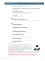
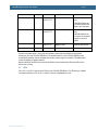
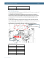
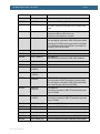
LPC3250 Developer’s Kit v2 - User’s Guide LCD_VD10 15 GREEN0 (LSB) LCD_VD11 16 GREEN1 LCD_VD12 17 GREEN0 (LSB) GREEN2 LCD_VD13 18 GREEN1 GREEN3 LCD_VD14 19 GREEN2 GREEN4 LCD_VD15 20 GREEN3 (MSB) GREEN5 (MSB) LCD_VD18 25 RED0 (LSB) LCD_VD19 26 BLUE0 (LSB) LCD_VD20 27 BLUE0 (LSB) BLUE1 LCD_VD21 28 BLUE1 BLUE2 LCD_VD22 29 BLUE2 BLUE3 LCD_VD23 30 BLUE3 (MSB) BLUE4 (MSB) The HSYNC, VSYNC, DEN control signals and the DOTCLK pixel clock signals must be connected to the display. All displays typically require the DOTCLK signal but there are variations on the control signals. o Some displays require all three control signals (HSYNC, VSYNC, DEN). o Some displays require only HSYNC and VSYNC. o Some displays require only DEN control signals. o Some displays require that HSYNC is delayed compared to VSYNC, i.e., VSYNC must have a falling edge before HSYNC (assuming that HSYNC/VSYNC are active negative) . If this is needed, HSYNC can be delayed one DOTCLK cycle with two Dtype flip-flops. In most cases the LPC3250 can generate the appropriate DOTCLK frequency. The higher the frequency needed, the fewer available frequencies can be selected when dividing the core clock. If a specific frequency is needed, the LCDCLKIN signal can be used. It is an input to the LPC3250. o Most displays can accept a quite wide range of frequencies on the DOTCLK signal. o Embedded Artists has successfully used LCDCLKIN signals up to 36MHz. The upper limit is not known exactly. It is typically related to the core clock frequency. If not used, leave this signal unconnected (i.e., LCDCLK is generated by the LPC3250). Some displays has a serial interface (typically SPI-like) for initialization of the controller chip inside the display. This is relatively common for smaller QVGA-sized displays but larger (resolution above QVGA – 320x240) displays typically do not require this initialization. o Copyright 2012 © Embedded Artists AB Page 62 The LCD Expansion connector has an SPI interface that supports both 3-wire transfer and 4-wire transfers. A 3-wire SPI interface typically means that 9 data bits are transferred in every time, 8 data bits and one bit indicating if it is a command or data byte. SPI-CLK, SPI-MOSI and SPI-SSEL are needed, i.e., 3 signals. For a 4-wire interface the transfers are 8 bits and a separate signal (the fourth wire) is used to signal if it is a command or data transfer. Signal SPI_LCD_DC is typically used for this.