1
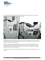
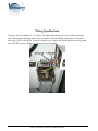
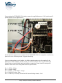
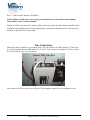
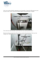
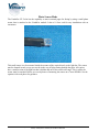
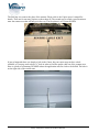
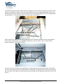
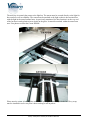
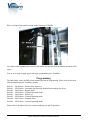
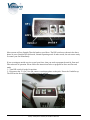
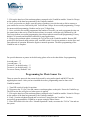
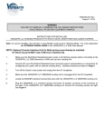
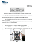
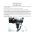
VendaFax
VF-1 Installation and Programming Guide
Parts List:
1 – #980006-001 - VendaFax VF-2 controller – 1 Ea
2 – # 500040-002 - Velcro Strips – 2 Ea
3 – # 608783-020 - Wiring harness – 1 Ea
4 - # 608784-010 – Photo Sensor Harness, 10 Ft. – 1 Ea
5 - # 608784-007 – Telephone patch cord, 7 Ft. – 1 Ea
6 - # 300297 – 18/22 AWG splice connectors – 6 Ea
7 - # 100014 – 4” Ty Wrap – 2 Ea
Dimensions: 4.675”L x 2.805”W x 1.325”H
Shipping weight – 1 Lb.
Patent Pending
www.vendapin.com/vendafax.html
Mounting Guidelines
Your VendaFax module has been supplied with 2 velcro strips for easy mounting virtually anywhere.
Simply affix the Velcro strips to the back of the VendaFax module. Remove the backing paper on the
Velcro and install on the back of the module as shown below.
Corporate Headquarter: 16381 Cherokee Road Brooksville, Florida 34601 352-796-2693
Factory: 21B Squires Street Cortland, NY 13045 607-428-0627
If you purchased a VENDAPIN 5596 Series, please refer to the photo below for the recommended
mounting location and orientation of the VendaFax module.
Please note the connections for the Telco Line In and To Fax are pointing up in the enclosure. There is
a diagnostic LED next to the switch array that must easily be seen for diagnostics. This also makes the
switches easy to get to for programming.
For other equipment, the mounting guidelines are the same. The VendaFax should be located in a
secure area where it cannot be tampered with other than by the owner of the equipment. We suggest
mounting the unit inside of the pay station for security. If this cannot be achieved, then we suggest
using a small lock box to secure the module.
Once you have the VendaFax secured in the desired position, you can proceed to making connections
to the unit.
Corporate Headquarter: 16381 Cherokee Road Brooksville, Florida 34601 352-796-2693
Factory: 21B Squires St. Cortland, NY 13045 607-428-0627
Wiring Specifications:
The power for the VendaFax is +12~24Vdc. The supplied harness has two wires (yellow and black)
with a fork terminal already on them. They are labeled +24V and GRND. Connect the +24V yellow
wire to the +24V on the DC/DC converter in the coin op. Connect the GRND black wire to the ground
on the DC/DC converter. Please see the photo below for details.
Corporate Headquarter: 16381 Cherokee Road Brooksville, Florida 34601 352-796-2693
Factory: 21B Squires St. Cortland, NY 13045 607-428-0627
If you purchased a VENDAPIN 5596, simply connect the supplied harness to J-10 3-position and 2position headers. See the photo below.
All the electrical connections are complete for the VENDAPIN 5596. For competitive vend devices,
please refer to the following section for proper interfacing.
If you are using another type of machine, the final termination points are to be supplied by the
Manufacturer of that machine. In other words, you will need to know where to get +24Vdc and
Ground, where to get an Enable signal, and where to connect the Count circuit for that specific
machine. Please refer to the wiring table below for specifications.
Pin 1 - +24Vdc - Yellow
Pin 2 – Ground - Black
Pin 3 – Enable - +5Vdc ONLY - Orange
Pin 4 – Enable DC return - Blue
Pin 5 – Count In (+5Vdc only with at least 1K current limiting resistor) - Red
Corporate Headquarter: 16381 Cherokee Road Brooksville, Florida 34601 352-796-2693
Factory: 21B Squires St. Cortland, NY 13045 607-428-0627
Pin 6 – Count Out (DC Return) - Red/White
NOTE: Failure to follow the correct wiring as described above will result in serious damage
and/or failure of the VendaFax module.
Simply cut off the 2 position and 3 position Molex connectors at the end of the harness installed on the
VendaFax module and discard. Use the supplied splice connectors to attach the wires to the necessary
locations as specified in the wiring table.
Line Connections
On the face of the VendaFax are two phone jacks. The jack closest to the DIP switches is “Telco Line
In”, the jack farthest from the DIP switches is “To Fax”. First, connect the supplied 7 ft. Telco cord to
the “Telco Line In” jack. See photo below.
Next, connect the Telco cord to your wall jack. This completes connections to your phone service.
Corporate Headquarter: 16381 Cherokee Road Brooksville, Florida 34601 352-796-2693
Factory: 21B Squires St. Cortland, NY 13045 607-428-0627
Now you are ready to make the connections to your fax machine. Connect the cable going out to your
fax device to the “To Fax” jack on the VendaFax module. See the photo below for details.
Next, connect the other end of the “To Fax” line to the “Line” jack on your fax device.
Route the two lines out the bottom of the enclosure as shown in the photo below. Please note this
routing is for a VENDAPIN product, cable routing may vary on other equipment.
Corporate Headquarter: 16381 Cherokee Road Brooksville, Florida 34601 352-796-2693
Factory: 21B Squires St. Cortland, NY 13045 607-428-0627
Photo Sensor Mode
The VendaFax VF-2 also has the capability to sense scanned pages for faxing by using a small photo
sensor that is attached to the VendaFax module. It has a 10 foot cord for easy installation with no
extensions.
This small sensor is to be mounted inside the scanner of the copier directly to the light bar. The sensor
must be located in such a way as to not be in the way of light coming through the glass. All copiers
have a small section of the light bar that is hidden and out of the actual scan range. This is where the
sensor must be attached. Below are several photos of mounting the sensor on a Canon iR2880i. See the
captions with each photo for guidance.
Corporate Headquarter: 16381 Cherokee Road Brooksville, Florida 34601 352-796-2693
Factory: 21B Squires St. Cortland, NY 13045 607-428-0627
The first step is to remove the glass of the scanner. Please refer to the Copier owner’s manual for
details. There are far too many copiers to show them all. The second step is to find a good location to
enter the scanner area that will not get in the way. The first photo is of a Canon iR2880i.
It just so happened there was already a hole in the Canon, but your copier may not have a hole
available, so you may need to drill a ¼” hole in order to feed the sensor cable out of the scanner area.
Here is a photo of a Samsung C8380ND where the application calls for a hole to be drilled. The hole is
on the right side of the scanner unit.
Corporate Headquarter: 16381 Cherokee Road Brooksville, Florida 34601 352-796-2693
Factory: 21B Squires St. Cortland, NY 13045 607-428-0627
Now the sensor cable must be routed inside the scanner so it does not bind or interfere with the normal
motion of the light bar. In the case of the Canon iR2880i there is an existing harness that sits in a tray
that already goes to the light bar. The sensor harness was routed right along side of the existing harness
and attached to it. View the photo below to see how this was achieved.
Please note there is plenty of slack in the cable to allow for smooth operation of the scanner light bar.
Also note the sensor harness runs UNDER the light bar to exit the copier. Here is a photo of the
harness routing on a Samsung C8380ND
As you can see, the routing for this application is much simpler on this particular copier. The routing
will vary from copier to copier, but the principles of allowing for enough slack and not interfering with
the movement of the light bar, and the harness not interfering with the light path remain the same on all
devices.
Corporate Headquarter: 16381 Cherokee Road Brooksville, Florida 34601 352-796-2693
Factory: 21B Squires St. Cortland, NY 13045 607-428-0627
The next step is to attach the sensor to the light bar. The sensor must he secured directly to the light for
best results as well as reliability. The sensor must be attached to the light so that is does not interfere
with the light in the actual scanned area. As previously mentioned, the best location is at the very end
of the bar that is under plastic trim or decals on the glass. It cannot be attached within the actual scan
area. First photos are from the Canon iR2880i.
Please note the sensor is held in place with a small ty wrap provided for you in the kit. The ty wrap
must be installed in such a way that it does not drag or rub anywhere.
Corporate Headquarter: 16381 Cherokee Road Brooksville, Florida 34601 352-796-2693
Factory: 21B Squires St. Cortland, NY 13045 607-428-0627
Here is a photo of the sensor location on the Samsung C8380ND.
Use caution when installing the sensor so that it does not interfere with the normal operation of the
copier
You are now ready to apply power and begin programming your VendaFax.
Programming
The chart below shows the DIP switch meaning and use in programming. Please refer to this chart
when programming your VendaFax module.
Switch 1 - On Position – Reserved for future use
Switch 1 – Off Position – Incoming ring detection disabled from sending fax device.
Switch 2 – On Position – Bypass mode.
Switch 2 – Off Position – Normal Operating mode.
Switch 3 – On Position – Pulse Test.
Switch 3 – Off Position – Normal Operating mode.
Switch 4 – On Position – Program mode.
Switch 4 – Off Position – Normal Operating mode.
Please refer to the photo below for switch numbering, on and off positions.
Corporate Headquarter: 16381 Cherokee Road Brooksville, Florida 34601 352-796-2693
Factory: 21B Squires St. Cortland, NY 13045 607-428-0627
Most systems will use Straight Thru dial mode to send faxes. The DIP switches as shown in the above
photo are set to Straight Thru dial mode, Normal Operating mode. In other words, the unit comes ready
to control your fax immediately.
If you are using an outside service to send your faxes, then you need to program the unit for Store and
Forward mode of operation. Please follow the instructions below to program for Store and Forward
mode.
1 – Turn DIP switch #4 to the On position
2 – Disconnect the “To Fax” line and connect a touchtone phone to that jack. Power the VendaFax up.
The LED on the face will glow red when power is applied.
Corporate Headquarter: 16381 Cherokee Road Brooksville, Florida 34601 352-796-2693
Factory: 21B Squires St. Cortland, NY 13045 607-428-0627
3 – Pick up the hand set of the touchtone phone connected to the VendaFax module. Listen for 2 beeps
on the speaker of the hand set generated by the VendaFax module.
4 – Once you hear the two beeps, enter the string of numbers you wish the unit to dial to connect to
your outside fax services, followed by #00. You will hear 2 beeps for successful programming, 3 beeps
for unsuccessful programming. Number can be up to 32 digits long.
5 – Once you have successfully programmed the number to forward, you need to program the time out
for connection to that service. Enter the desired time (in seconds, two digits only) followed by #40.
Two beeps indicate successful programming, three beeps indicate unsuccessful programming. Factory
default is 10 seconds and should be sufficient for most applications.
6 – Hang up the touchtone phone, reconnect the To Fax line to the VendaFax module. Restore DIP
switch #4 to the Normal mode position (off), turn DIP switch #2 to the on position to use the Store and
Forward mode of operation. Return the bypass to normal operation. The basic programming of the
VendaFax unit is complete.
For special characters or pauses in the dial string, please refer to the chart below for programming.
4 second pause - *7
1 second pause - *8
To enter a * in the dial string - **
To enter a # in the dial string - *#
To reset to Factory Defaults - ###
Programming for Photo Sensor Use
There are some fax protocols that cannot be detected by using audio signals and MUST use the
supplied photo sensor. After you have installed the sensor, programming must be done to the
VendaFax module.
1 – Turn DIP switch #4 to the On position
2 – Disconnect the “To Fax” line and connect a touchtone phone to that jack. Power the VendaFax up.
The LED on the face will glow red when power is applied.
3 – Pick up the hand set of the touchtone phone connected to the VendaFax module. Listen for 2 beeps
on the speaker of the hand set generated by the VendaFax module.
4 – Enter *4 on the telephone keypad and wait to hear 2 beeps from the VendaFax. You have
successfully programmed the VendaFax to operate using the Photo Sensor.
5 – Place DIP switch #4 in the off or “Normal Operations” mode, reconnect the “To Fax” line and use
the system.
Corporate Headquarter: 16381 Cherokee Road Brooksville, Florida 34601 352-796-2693
Factory: 21B Squires St. Cortland, NY 13045 607-428-0627
To test the system, scan a sheet of paper and watch the LED on the front of the VendaFax module.
When the light bar is turned on, you should see the LED blink as it receives the pulse from the Photo
Sensor.
The basic operation of Sensor Mode is as follows:
1 – Patron inserts money into vend device.
2 – Patron uses the copier fax system to enter the phone number and scan a document. As the document
is scanned, a pulse is sent to the VendaFax Module for each scanned page, then stored in the internal
memory.
3 – When the copier takes the phone off the hook, the string of pulses are then sent to the vend device
to deduct money.
4 – If the fax transmission fails, the copier will attempt to redial and send the fax. This is allowed with
this system as the fax was already paid for in advance.
Programming the Vend Device
Covered here are the programming instructions for VENDAPIN model 5596. The theory and general
parameters are the same for any vend device.
1 – Connect your VENDAPIN 5596 to either Set Up Express or use the embedded web browser. See
owner’s manual for details.
2 – Open the tab marked VendaFax in Set Up Express or web browser.
3 – Set price 1 to the desired price for the FIRST FAXED PAGE ONLY. Set price 2 to the desired
price for every subsequent page. Click save settings or the settings will not be retained in memory
4 – Go to the General tab in either Set Up Express or web browser. Set the No Activity Timeout for a
MINIMUM of 120 seconds. Factory default is 180 seconds for all VENDAPIN products. Click save
settings.
5 – For a different brand of machine than VENDAPIN, please refer to the device owner’s manual to
find the settings you need. VENDAPIN has created internal software for a dual price system on the
5596. All other equipment will only be able to charge a single price.
Basic Operation of Straight Thru Dialing Mode
1 - When the host fax device comes off hook, it is directly connected to the incoming phone line. The
host fax device must do it’s own dialing of the numeric string while the VF-1 monitors for the
characteristic audio signature of a faxed page.
2 - Once the characteristic audio signature of a faxed page is detected by the VF-1, the VF-1
momentarily turns OFF it’s front panel LED for 150 mSec.
3 - The VF-1 then pulses it's output for 100mSec (+0/- 8 mSec) to the Raptor 2 or other vending
device.
4 - If the host fax device has not hung up, the VF-1 continues to repeat the audio detection cycle.
5 - When a hang up is detected, the last pulse from the VF-1 is sent out of the opto circuit to the
Raptor 2 or other vending control device.
Corporate Headquarter: 16381 Cherokee Road Brooksville, Florida 34601 352-796-2693
Factory: 21B Squires St. Cortland, NY 13045 607-428-0627
Basic Operation of Store and Forward Mode
1. When the host fax device comes off hook, it is connected to an artificial line within the VF-1
and the dial tone is provided to the host fax device.
2. Any “Touch Tones” sent by the host fax device are stored in the temporary volatile RAM of the
VF-1.
3. If no tones are detected within 15 seconds, a “Busy Tone” is sent to the host fax device.
4. Only a “Hang Up” from the host fax device will reset the VF-1 out of this mode.
5. If at least one tone is detected and there has not been any additional tones for 3 seconds, then
the VF-1 seizes the phone line and dials the phone number string that has been pre-programmed
via #00.
6. After this stored pre-programmed number string is sent, the VF-1 monitors the phone line for
“Call Progress” if dip switch 3 is ON.
7. If dip switch 3 is OFF, after the stored pre-programmed number string is sent, the VF-1 waits
the time out period in programming mode position #40.
8. After this sequence of events, the VF-1 dials the stored phone number string that the host fax
device had originally dialed.
9. The last step is that the VF-1 allows the connection to the receiving fax device phone line.
10. From this point forward, the sequence is the same as the Straight Thru Mode.
NOTE: In either mode, the transmitting/receiving phone line will be restricted (relay contact opens in
the VF-1 for the phone line) if an attempt is made to transmit more pages than the amount of money
entered into escrow of the vending access controller (Raptor 2 or other vending control device) within
5 seconds of the last paid page sent.
Corporate Headquarter: 16381 Cherokee Road Brooksville, Florida 34601 352-796-2693
Factory: 21B Squires St. Cortland, NY 13045 607-428-0627
Notice
The material contained in this manual is subject to change without notice. No part of this manual may
be reproduced or used in any form or by any means, electronic or mechanical, including photocopying
or electronic transmission or other means of reproduction or distribution without prior written consent
of VENDAPIN. The drawings, specifications, and other technical information contained in this manual
are the property of VENDAPIN and shall not be copied, reproduced or used in any way, in whole or in
part, as the basis of manufacture or sale of similar items without the prior written consent of
VENDAPIN.
FCC Warning
This equipment generates, uses, and can radiate radio frequency energy and if not installed and used
in accordance with the instructions in this manual may cause interference to radio communications.
Operation of this equipment in a residential area is likely to cause interference, in which case the user
at her/his own expense will be required to take whatever measures may be required to correct the
interference.
Information to User
This equipment must be installed and used in strict accordance with the manufacturer’s
instructions.
VENDAPIN is not responsible for any radio or television interference caused by unauthorized
modification of this equipment or the substitution or attachment of connecting cables and equipment
other than those specified by VENDAPIN. The correction of interference caused by such unauthorized
modification, substitution or attachment will be the responsibility of the user.
One-Year Warranty and Service Policy
VENDAPIN LLC. warrants to the purchaser that this VENDAPIN product, hereinafter called “the
unit,” is free from defects in materials and the workmanship for a period of one year from the date of
purchase. If any such defect is discovered within the first 90 days of the warranty period, VENDAPIN
LLC will repair or replace the unit free of charge. If any such defect is discovered after 90 days and up
to the end of the one-year warranty period, VENDAPIN LLC will repair the unit free of charge. All
warranty repair and replacement actions are contingent on verification of the defect(s) or
malfunction(s) and upon prepaid delivery of the unit to VENDAPIN LLC, 21B Squires St., Cortland,
NY, 13045 by parcel post, common carrier, UPS or other commercial means. This warranty does not
apply to normal wear, to tampering or alterations resulting in cracked or broken components, or to units
damaged by excessive heat, cold or moisture.
To preserve your rights under the warranty, you must provide proof of purchase for the returned unit.
RETURNING THE PRODUCT REGISTRATION “CUT-OUT” CARD enclosed in this manual with
the new unit will also register the warranty by serving as proof. Otherwise, a copy of the sales invoice
showing the serial number of the returned unit must accompany the unit as proof of purchase.
Corporate Headquarter: 16381 Cherokee Road Brooksville, Florida 34601 352-796-2693
Factory: 21B Squires St. Cortland, NY 13045 607-428-0627
If your unit is delivered to VENDAPIN LLC lacking proof of purchase, and we are unable to otherwise
verify date of purchase, we will assume the purchase date of the unit was prior to the one-year warranty
period. It will then be serviced under the terms of VENDAPIN LLC.'s Service Policy.
Our sole and exclusive liability for defects in materials and workmanship shall be limited to repair or
replacement of the unit at our service center and we shall not be liable for incidental, contingent, or
consequential damages.
This warranty does not obligate us to bear any of the costs of transportation charges in connection with
repair or replacement of the unit or any defective parts of the unit.
This warranty is invalid if the damage or defect to the unit is caused by accident, Acts of God, customer
abuse, misuse, unauthorized alteration or repair, or vandalism by third parties.
This warranty is made in lieu of any other expressed warranty and except for the foregoing warranty,
which is exclusive, there is no other expressed warranty being made.
This warranty gives you specific legal rights. You may have other rights, which vary according to the
state, or country in which the unit was sold.
Disclaimer
This equipment is serviceable by a trained and qualified technician.
Parts and Service Policy
This policy requires you to ship prepaid to us, the unit or major components of the unit, under a
Return Authorization for repair. VENDAPIN LLC shall not be obligated to service or supply
parts for any unit after seven years from date of purchase.
Charges for return shipping, parts and service will be incurred, as applicable, at the prevailing rates.
VENDAPIN LLC will enclose a copy of the return authorization (RA#) with your unit. This
authorization details the work performed and the costs incurred. Please refer to the RA# in future
communications with VENDAPIN LLC about this unit. This policy is for coverage within the
continental U.S. only.
Corporate Headquarter: 16381 Cherokee Road Brooksville, Florida 34601 352-796-2693
Factory: 21B Squires St. Cortland, NY 13045 607-428-0627
Return Authorizations
All units returned to VENDAPIN LLC must be shipped with a return authorization number (RA#)
affixed to the outside of the shipping container and addressed to:
Technical Service Department
VENDAPIN LLC
21B Squires St
Cortland, New York 13045
VENDAPIN LLC reserves the right to refuse any incoming shipment not marked with an RA#
on the outside of the shipping container.
VENDAPIN LLC will issue a Return Authorization Number upon receiving a written request at the
above address or a request by phone at +1.607.428.0627 (customers should ask for the Technical Service
Hotline). Please provide the model number and serial number of the unit or the unit that contained
the component(s) you wish to return.
For non-warranty service, please be prepared to supply a purchase order, VISA, MasterCard or
American Express authorization, or make other payment arrangements as required. Within the
continental United States, you may request that your serviced unit be returned to you on a C.O.D. basis.
Contacts:
Sales: 352-796-2693
Service: 352-678-3021
352-678-3027
© 1999-2008 VENDAPIN LLC. All rights reserved.
Printed in the U.S.A.
Corporate Headquarter: 16381 Cherokee Road Brooksville, Florida 34601 352-796-2693
Factory: 21B Squires St. Cortland, NY 13045 607-428-0627