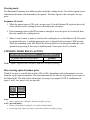
1
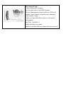
DATATRON III SERIES
MODELS 5882 and 5885
Datatron III Series Operator’s Manual
© 1999-2008 VENDAPIN LLC. All rights reserved.
Printed in the U.S.A. (revised: 01/08)
5885 Keypad with 1000 PIN accounts and dual counters: Part number 945885-002
5882 Keypad with 2000 PIN accounts and single counter: Part number 945882-002
See firmware version table for full list of features including standard or steering functions.
This manual is applicable to firmware versions 4.11-1 and higher.
VendaCard® is a registered trademark of VENDAPIN LLC.
Notice
The material contained in this manual is subject to change without notice. No part of this manual
may be reproduced or used in any form or by any means, electronic or mechanical, including
photocopying or electronic transmission or other means of reproduction or distribution without
prior written consent of VENDAPIN LLC. The drawings, specifications, and other technical
information contained in this manual are the property of VENDAPIN LLC and shall not be
copied, reproduced or used in any way, in whole or in part, as the basis of manufacture or sale of
similar items without the prior written consent of VENDAPIN LLC.
FCC Warning
This equipment generates, uses, and can radiate radio frequency energy and if not installed and
used in accordance with the instructions in this manual may cause interference to radio
communications.
Operation of this equipment in a residential area is likely to cause interference, in which case the
user at her/his own expense will be required to take whatever measures may be required to
correct the interference.
Information to User
This equipment must be installed and used in strict accordance with the manufacturer’s
instructions.
VENDAPIN LLC is not responsible for any radio or television interference caused by
unauthorized modification of this equipment or the substitution or attachment of connecting cables
and equipment other than those specified by VENDAPIN LLC. The correction of interference
caused by such unauthorized modification, substitution or attachment will be the responsibility of
the user.
Two-Year Warranty and Service Policy
VENDAPIN LLC warrants to the purchaser that this VENDAPIN product, hereinafter called “the
unit,” is free from defects in materials and the workmanship for a period of two (2) year from the
date of purchase. If any such defect is discovered within the first 90 days of the warranty period,
VENDAPIN LLC will repair or replace the unit free of charge. If any such defect is discovered
after 90 days and up to the end of the two-year warranty period, VENDAPIN LLC will repair the
unit free of charge. All warranty repair and replacement actions are contingent on verification of
the defect(s) or malfunction(s) and upon prepaid delivery of the unit to VENDAPIN LLC, 21B
Squires Street, Cortland, New York USA 13045 by parcel post, common carrier, UPS or other
commercial means. This warranty does not apply to normal wear, to tampering or alterations
resulting in cracked or broken components, or to units damaged by excessive heat, cold, or
moisture.
To preserve your rights under the warranty, you must provide proof of purchase for the returned
unit. Returning the Warranty Registration card shipped with the new unit will register the warranty.
Otherwise, a copy of the sales invoice showing the serial number of the returned unit must
accompany the unit as proof of purchase.
If your unit is delivered to VENDAPIN LLC lacking proof of purchase, and we are unable to
otherwise verify date of purchase, we will assume the purchase date of the unit was prior to the
one-year warranty period. In such instances, the unit will then be serviced under the terms of
VENDAPIN LLC's Service Policy.
Our sole and exclusive liability for defects in materials and workmanship shall be limited to
repair or replacement of the unit at our service center and we shall not be liable for incidental,
contingent, or consequential damages.
This warranty does not obligate us to bear any of the costs of transportation charges in connection
with repair or replacement of the unit or any defective parts of the unit.
This warranty is invalid if the damage or defect to the unit is caused by accident, Acts of God,
customer abuse, misuse, unauthorized alteration or repair, or vandalism by third parties.
This warranty is made in lieu of any other expressed warranty and except for the foregoing
warranty, which is exclusive, there is no other expressed warranty being made.
This warranty gives you specific legal rights. You may have other rights, which vary according to
the state, or country in which the unit was sold.
Disclaimer
This equipment is serviceable by a trained and qualified technician.
Parts and Service Policy
This policy requires you to ship prepaid to us, the unit and/or major components of the unit,
under a Return Authorization for repair. VENDAPIN LLC shall not be obligated to service or
supply parts for any unit after seven years from date of purchase.
Charges for return shipping, parts, and service will be incurred, as applicable, at the prevailing
rates.
VENDAPIN LLC will enclose a copy of the completed return authorization (RA) with your unit.
This authorization details the work performed and the costs incurred. Please refer to the RA
number in future communications with VENDAPIN LLC about this unit.
This policy is for coverage within the continental U.S. only.
Return Authorizations
All units returned to VENDAPIN LLC must be shipped with a return authorization number (RA)
affixed to the outside of the shipping container and addressed to:
Technical Service Department
VENDAPIN LLC.
21B Squires Street
Cortland, New York USA 13045
VENDAPIN LLC reserves the right to refuse any incoming shipment not marked with an
RA number on the outside of the shipping container.
VENDAPIN LLC will issue a Return Authorization Number upon receiving a written request at
the above address or a request by phone at +1.607.352-678-3021 (customers should ask for the
Technical Service Hotline). Please provide the model number and serial number of the unit or
the unit that contained the component(s) you wish to return.
For non-warranty service, please be prepared to supply a purchase order, VISA, MasterCard, or
American Express authorization, or make other payment arrangements as required. Within the
continental United States you may request that your serviced unit be returned to you on a C.O.D.
basis.
Preface
Models covered in this manual
This manual applies to firmware versions 4.11-1 and higher. This manual covers the models
shown in the following table.
Model number
Card type
Part number
5882
5885
CR-80 card reader
CR-80 card reader
945882-002
945885-002
2000 PIN
1000 PIN
Single count
Dual count
An optional Model 5884 portable printer (945884-001) may be used to print out an account audit.
• This is a plain paper printer. Replacement paper may be ordered from VENDAPIN LLC.
•
A replacement ribbon is also available. See Parts List.
What’s new in this release
Normal and Steering mode Operation
The firmware installed in your device determines the mode of operation you will be running. The
firmware version usually displays at power-up. You can also read it in idle state (ENTER
DATATRON PIN CODE) by simply pressing *. Your firmware version will display briefly. Make
a note of this in your manual, as you will need it if you need to call for support. The table below
shows how the firmware version relates to the features in your unit, which is chosen to match your
copier.
Version
4.11-1
4.12-1
4.13-1A
4.14-1A
4.11-2
4.13-2
Displayed Count/Price
(One) Count/Price
(Two) M-1 Master, P-1 Print
(Two) C-1 count, C-2 count
(Two) M-1 Master, P-1 Print
(One) Count/Price - STEERING MODE
(Two) C-1, C-2 – STEERING MODE
Accounts
2000
1000
1000
1000
2000
1000
Standard Mode uses
• An enable relay closure to allow the copy process to begin.
• A pulse back on Opto 1 from the copier indicates that a Price 1 copy has been completed.
• A pulse back on Opto 2 from the copier indicates that a Price 2 copy has been completed.
Steering Mode uses
• An enable relay closure to allow the copy process to begin.
• A pulse back on Opto 1 from the copier indicates that a copy has been completed.
• A steady low level on Opto 2 line indicates the copy is Price 1.
• A steady high level on Opto 2 line indicates the copy is Price 2.
About the Product
A Datatron III Series product is a dual-mode device that controls access to printers, copiers,
duplicators, or any other device controllable with a relay closure. Customers use PIN accounts to
pay for products or services.
Vend price structure
The Datatron III supports pricing based on patrons paying for services using PIN numbers entered
on the keypad. The device allows up to two prices.
Copy mode
Patrons are charged for each transaction. Prices are set in the VENDAPIN device.
Cards accepted
The unit will accept only program cards for administrative use.
Dual print/copy operation
The Datatron III was designed to simultaneously control the print and copy modes of
multifunction copiers networked to PCs.
Transaction history
The Datatron III has an extensive capability for tracking vending activity. History meters are
viewed on the display, printed out, or uploaded to a PC and imported into a spreadsheet.
Licenses and Program cards
Before a unit leaves the factory, it is configured with a license, facility or site code (which you
can’t change), and up to 2000 programmable PIN codes. You will receive a set of program cards
with your Datatron III system. These program cards contain license codes that match the codes
programmed into your unit(s).
There are no user cards. Users enter PIN numbers on the keypad to activate the Datatron III.
The utility software CD you received with your Datatron III activates computer communications,
not this card.
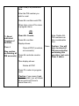
The Control Card
Adds or deletes PIN accounts.
Sets the total value of each PIN Account.
The site administrator assigns each user a PIN code,
which is entered on the keypad by users when they
want to make a copy.
Audits or clears individual counters, or the master
total counter.
Sets Price 1 and Price 2.
Sends audit data to a printer.
Enables or disables the beep when each key is pressed.
Getting Started
Setting up the unit
Connecting the unit to the host device
Installation instructions tailored to the product you ordered should have been included with the
shipment of your unit(s).
Vending from a copier
If you’re connecting to a copier, a machine harness, specific to the make and model of your
copier, will be required.
Vending reports to a computer
If you are using a computer to track activity:
• Attach the serial cable you received with your Datatron III from the RJ-11 port on the back
of the Datatron III to a spare DB-9 COM port on your computer. Do not substitute data
cables designed for other device as improper operation or damage may result
• Once the unit is powered up (see below), make sure the baud rate of the computer is set to
the baud rate of the Datatron III. The software (contained on the Datatron III CD you
received) running on the host PC should help you set the baud rate to achieve optimal
performance.
• Install the print vend software and monitored printers according to the instructions provided
on the software CD.
Powering up the Print/Datatron III
Plug the Datatron III into a 3-prong, grounded wall outlet. The unit will cycle through its boot-up
sequence, displaying the firmware version. If you ever need to call or email VENDAPIN LLC
customer service, you may be asked to provide this boot-up information. Please note the
displayed version numbers and write them in the spaces provided on the last page of this manual.
Firmware version
This is the version of the firmware issued with your unit.
Site Code
The unit is programmed with a site code unique to the customer site. It matches your Control
Card(s).
Your Unit
Programming the unit
Modifying parameters
The unit must be in program mode to modify parameter values. Values can include PIN numbers
for users, and the authorized number of copies for two prices.
Insert the Control Card that came with your unit to enter program mode. You will find that it
works best if you insert it with a quick, smooth motion.
Note: A computer cannot be used for changing parameter settings on the Datatron III.
Configuring the unit for print or copy vending
When you first turn on the unit, it will be in standby mode, ready for user input, and display:
ENTER DATATRON PIN CODE
Insert the Control Card. The display will change to
MACHINE
LOAD COMMAND:
Enter the Menu Parameters as shown in the following table to control the features and prices.
Control Card Menu Selections and Parameters
NOTE: TO EXIT PROGRAM MODE AT ANY TIME, PRESS C TO GET TO MAIN
MENU, AND REMOVE THE CONTROL CARD. This returns the machine to a normal User
Mode idle condition
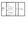
Parameter
Menu
Description
Provides keypad-only access to the
maintenance menu.
Enter the first PIN number.
Default
Range
For PV1 (or print value 1) enter the
number of copies authorized for
Price 1.
For PV2, enter the number of
copies authorized for Price 2.
To Add PIN
Numbers,
Press 1
Press A to confirm values for this
PIN.
If you do not press A, no change
or entry is made.
None
PIN: 0-2000
PV: 0-999999.99
None
0 – 2000
Continue for as many PIN numbers
as you wish.
Press C to cancel and return to
main program mode menu at any
time.
Enter PIN number.
To Delete a
Press A to confirm each PIN.
Specific PIN
account number, Continue for as many PIN numbers
as you wish to delete.
Press 2
Press C to cancel and return to
main program menu.
To Delete All PIN
Deletes all PIN number accounts as
Number
if you were setting up a new
accounts,
machine.
Press 3
(See caution on
Deleting all PIN
accounts)
Press A to confirm.
Press C to cancel and return to
program mode main menu.
Note: Deleting all PIN
numbers can take a
considerable time.
None
Caution: You will have
to reload all PIN
accounts after
performing this
operation.
Clear ONE (PIN) count.
Enter the PIN you wish to reset.
Press A to confirm each PIN.
When done, press C to return to
program menu.
-ORTo Reset
individual
COUNTERS of
All PINS,
Clear ALL Counts.
Press A to confirm.
Note: Deleting ALL PIN
Numbers can take
considerable time.
Display shows:
Press 4
Clear all PIN? (counters, not
accounts).
None
Press A to activate counter clear.
(See caution on
Deleting all PIN
accounts)
Then display shows:
Caution: You will have
to reload all PIN
accounts after
performing this
operation, just as in
Press 3 above.
Delete all PIN?
Press C to return to program menu.
Caution: if you press A (not
recommended), you will delete all
accounts and have to reload them
all as if you were initializing.
Enter the PIN you wish to audit,
followed by the A key.
Display will show:
To View Counts
for ONE PIN,
PV1: XXXXXX.XX
M: XXXXXX.XX
Press S to advance to next screen:
Press 5
PV2: XXXXXX.XX
P: XXXXXX.XX
Press C to exit program mode to
main menu.
None
PIN: 0 – 2000
PV: 0 - 999999.99
Display shows:
1. Total count
To Audit or Clear
2. Total copies
Master
Select and press your choice 1 or 2.
Counters,
Read meter.
Press 6
Select * to clear count to zero.
None
0 – 999999.99
None
0 – 99.99
None
0 – 99.99
None
See Printer
Troubleshooting if you
have problems.
Select C to quit without resetting.
Display shows:
To Set PRICE
ONE
Press 7
#1 PRICE
O: (Original Price) N: XX.XX
To exit without changing, Press C.
Enter the new price and Press A to
change.
Press C to return to Program mode
Display shows:
#2 PRICE
O: (Original Price) N: XX.XX
To Set PRICE
TWO
Press 8
To Send Data to
a Printer
connected to the
RJ11 port
Press 9
To toggle the
Beep when a key
is pressed
To exit without changing, Press C.
Enter the new price and Press A to
change.
Press C when finished to return to
Program mode menu.
Display shows:
Print Data?
A= YES C= NO
Press A and wait for printer to finish
Display shows:
Set Counter
Beep ON
ON
Press A to toggle it ON or OFF.
Press 0
Press C to return to Program mode
menu.
N/A
No Activity timer
The amount of time the Datatron will remain active after the last transaction. Factory default is 60
seconds.
PIN Codes
What are PIN codes?
A PIN code is a number encoded in the Datatron III unit that identifies the user. For example, in a
university setting, each group of freshmen, sophomores, juniors, seniors, and staff could each be
assigned a distinct personal or group access PIN. VENDAPIN offers up to 2000 access PIN
numbers, depending on model and firmware.
The unit logs every transaction made by each PIN code. If the PIN code entered on the keypad
doesn’t match one of those programmed onto the unit, the display shows: “PIN code illegal” and
the Datatron III will not permit the transaction.
Purpose of PIN numbers
• PIN numbers provide a way to track usage patterns of different user groups.
• You can factor PIN numbers into your pricing structure, and set transaction prices and
access to more costly features such as color printing.
• PIN numbers provide a security mechanism. PIN numbers will work at your location
only if they match an authorized PIN stored in your Datatron III.
Reasons for changing PIN numbers
When you receive new units from the factory, you will need to create accounts and the authorized
value in each account. Existing customers might need to set their unit’s PIN numbers for the
following reasons:
• If you’re adding new access codes, in addition to the existing ones, or changing the values
authorized to each user.
• If you’re purging old access codes, and then replacing them with new ones.
Setting Copy Prices
Using the Price Menus
You can set two prices on a Datatron III.
When you first turn on the unit, it will be in standby mode, ready for user input, and display:
ENTER DATATRON PIN CODE
Insert the Control Card. The display will change to:
MACHINE
LOAD COMMAND:
Enter the menu Parameters as shown in the following table to control the prices.
Parameter listing
The table below lists the parameters in the order in which they appear on the display, and gives
the acceptable range of values and corresponding default setting for each parameter.
NOTE: TO EXIT PROGRAM MODE AT ANY TIME, PRESS C TO GET TO MAIN
MENU, AND REMOVE THE CONTROL CARD. This returns the machine to a normal User
Mode idle condition.
Parameter
Menu
Description
Provides keypad-only access
to the maintenance menu.
Display shows:
Default Range
#1 PRICE
O: (Original Price) N:
XX.XX
To Set PRICE
ONE
To exit without changing,
Press C.
Press 7
Enter the new price and Press
A to change.
None
0 – 99.99
None
0 – 99.99
Press C when done to return
to Program mode menu.
Display shows:
#2 PRICE
O: (Original Price) N:
XX.XX
To Set PRICE
TWO
Press 8
To exit without changing,
Press C.
Enter the new price and press
A to change.
Press C when done to return
to Program mode menu.
Using Meters
About meters
All vending activity is recorded by an extensive set of internal electronic meters.
• Master Count meter. Provides a tamper-proof record of all the counts made on the unit.
• Individual meters. Allow for periodic recording of transactions. All PIN accounts come
with one (or generally) two individual meters. Depending on your firmware, they may be a
Master or Copy pair or a Print Value 1 and Print Value 2 type count. They are usually
viewed, then reset with value on a regular basis.
1. Viewing and resetting meters on the Datatron LCD display
You can view both total and individual meters directly on the display or upload them to a PC
using VENDAPIN’s Datatron III CD. The manual keypad meter-reading technique is shown in
the table below.
When you first turn on the unit, it will be in standby mode, ready for user input, and display:
ENTER DATATRON PIN CODE
Insert the Control Card. The display will change to:
MACHINE
LOAD COMMAND:
Enter the menu Parameters as shown in the following table to control meters.
Parameter listing
The table below lists the parameters in the order in which they appear on the display, the
acceptable range of values, and the default setting for each parameter.
NOTE: TO EXIT PROGRAM MODE AT ANY TIME, PRESS C TO GET TO MAIN
MENU, AND REMOVE THE CONTROL CARD. This returns the machine to normal User
Mode idle condition.
Parameter
Description
Default Range
Provides keypad-only access
Menu
to the maintenance menu.
Clear ONE (PIN) count.
Enter the one Pin you wish to
reset.
Press A to confirm each PIN.
When done, press C to return
to program menu.
-OR-
To Reset
individual
Counters of
All PINS,
Press 4
Clear ALL Counts.
Press A to confirm.
Note: Delete ALL
PIN numbers can
take considerable
time.
Display shows:
Clear all PIN? (counters,
not accounts).
(See caution
Press A to activate counter
on Deleting all clear.
PIN accounts) Then display shows:
Delete all PIN?
Press C to return to program
menu.
Caution: if you press A (not
recommended), you will delete
all accounts and have to
reload them all as if you were
initializing.
None
Caution: You will
have to reload all
PIN accounts after
performing this
operation, just as in
Press 3 above.
Enter the one PIN you wish to
audit, followed by the A key.
Display will show:
To View
Counts for
ONE PIN,
Press 5
PV1: XXXXXX.XX
M: XXXXXX.XX
Press S to advance to next
screen:
PV2: XXXXXX.XX
P: XXXXXX.XX
None
PIN: 0 – 2000
PV: 0 - 999999.99
None
0 – 999999.99
None
N/A
Press C to exit program mode
to main menu.
Display shows:
1. Total count
2. Total copies
To Audit or
Clear Master
Counters,
Select and press your choice 1
or 2.
Read meter.
Press 6
Select * to clear count to zero.
Select C to quit without
resetting.
Display shows:
To Send Data
to a Printer
connected to
the RJ11 port
Press 9
Print Data?
A= YES C= NO
Press A and wait for printer to
finish
2. Printing meters
To print out meters to a portable serial printer:
• Insert the Control Card as described above.
• Be sure the printer-style serial cable is attached correctly to both devices.
• Press 9 on the keypad as described above.
• The resettable meters will print first, followed by the non-resettable meters.
• When printing meter totals, all categories are printed, even if they are valued at $0.00.
• Individual meters print only if they contain a value.
• You can send the data to a computer installed with the software on the CD that came with
your unit.
Sample Datatron Meters Printout
PIN:000000
PV1:000100.00
PV2:000050.00
Masters:000000.00
Prints: 000000.00
PIN:000001
PV1:000060.00
PV2:000025.00
Masters:000000.00
Prints: 000000.00
PIN:000003
PV1:000200.00
PV2:000100.00
Masters:000000.00
Prints: 000000.00
PIN:000004
PV1:000050.00
PV2:000000.00
Masters:000000.00
Prints: 000000.00
PIN:000005
PV1:000020.00
PV2:000005.00
Masters:000000.00
Prints: 000000.00
Total Masters: 000000.00
Total Prints: 000000.00
3. Downloading Meters to a Computer Database
Datatron III Download Software CD
• Follow the instructions on the CD to properly set up the computer to receive data from the
Datatron III unit.
• Be sure the Com Port number, baud rate, and parity are correct.
• Be sure the computer style serial cable is correctly attached and not damaged.
PIN Accounts
PIN account basics
The Datatron III supports account numbers ranging from 0 to 999999, and each Datatron III can
store up to 2000 accounts at one time, depending on the firmware.
PIN numbers behave like credit cards. Unlike debit cards, which store an actual value that is
decreased each time the card is used, PIN accounts invoke an account number stored on the
Datatron, which is tied to one or two print meters (depending on firmware). Every time the PIN is
used, Datatron III records the number of vends made to the PIN account by incrementing an
internal counter (or meter). After each transaction, the unit compares the copy meter against the
account’s vend limit. When the vend limit is reached, the PIN code is locked out and can’t be used
in that machine until the administrator resets the counter.
The Datatron III employs up to two internal copy meters to track the number of copies made by a
PIN account. Each meter is assigned to a different type of copy or print (e.g., black & white, color,
size). We’ve provided parameters you can set to limit the total number of copies or prints a
customer can charge to an account. When the limit is reached, a message is momentarily flashed
on the display and vending is terminated. The user cannot use the PIN account in that machine
until the account’s meters are reset.
The Datatron III allows you to impose different vend limits on each account number. When a new
account created, you must determine the limit on each meter. The PIN account will be locked out
when the vend limit is reached.
Creating PIN accounts
The table below gives an example of how to set these parameters.
Parameter listing
The table below lists the parameters in the order they appear on the display, the acceptable range
of values, and the default setting for each parameter.
When you first turn on the unit, it will be in standby mode, ready for user input, and display:
ENTER DATATRON PIN CODE
Insert the Control Card in a swift smooth motion. The display will change to
MACHINE
LOAD COMMAND:
Enter the menu Parameters as shown in the following table to control the prices.
Parameter
Menu
Default Range
Description
Provides keypad-only access
to the maintenance menu.
Enter the first Pin Number.
For PV1 (or print value 1) enter
the number of copies
authorized for Price 1.
For PV2, enter the number of
copies authorized for Price 2.
To Add PIN
Numbers,
Press A to confirm values for
this PIN.
Press 1
If you do not press A, no
change or entry is made.
None
PIN: 0-2000
PV: 0-999999.99
None
0 – 2000
Continue for as many PIN
Numbers as you wish.
Press C to cancel and return to
main program mode menu at
any time.
Enter PIN number.
To Delete a
Specified PIN
account
number,
Press 2
To Delete All
PIN Number
accounts,
Press 3
Press A to confirm each PIN.
Continue for as many PIN
numbers as you wish to delete.
Press C to cancel and return to
main program menu.
Deletes all PIN number
accounts as if you were setting
up a new machine.
Press A to confirm.
(See caution
Press C to cancel and return to
on Deleting all
program mode main menu.
PIN accounts)
None
Clear ONE (PIN) count at a
time.
Enter the PIN number you
wish to reset.
Press A to confirm each PIN.
When done, press C to return
to program menu.
-ORTo Reset
individual
Counters of
All PINS,
Press 4
Clear ALL Counts.
Note: Delete ALL
PIN numbers can
take considerable
time.
Press A to confirm.
Display shows:
None
Clear all PIN? (counters,
not accounts).
(See caution
on Deleting all
Press A to activate counter
PIN accounts)
clear.
Then display shows:
Delete all PIN?
Press C to return to program
menu.
(Caution: if you press A (not
recommended), you will delete
all accounts and have to
reload them all.)
Caution: You will
have to reload all
PIN accounts after
performing this
operation, just as in
Press 3 above.
Enter the PIN you wish to
audit.
Press A.
Display will show:
To View
Counts for
ONE PIN,
Press 5
PV1: XXXXXX.XX
M: XXXXXX.XX
Press S to advance to next
screen:
PV2: XXXXXX.XX
P: XXXXXX.XX
Press C to exit program mode
to main menu.
None
PIN: 0 – 2000
PV: 0 – 999999.99
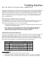
Vending Interface
How the Datatron III and Copier communicate
Every time a customer makes a selection on a copier, pulses (signals) are detected by the Datatron
III through an optical isolator or opto. Optos allow the unit to see a particular signal condition
inside the copier. Based on the customer’s selection, individual optos are turned on or off. The
debit price is determined by the collective state of the optos. The firmware determines whether
there is enough money to cover the vend, and if so, turns on a relay (switch) that enables the
device to make the vend.
Pulse detection in standard and steering modes
The Datatron III connects to the host device via a machine harness, which plugs into the 9-pin
white, AMP Mate-n-Lok connector. The Datatron uses either a standard or steering pulse
detection to intercept signals it receives over that connection.
• Configuring the terminal to operate in standard or steering mode requires proper selection
of a Datatron III model and firmware.
• Note: Incorrectly wiring machine harness will result in equipment malfunction
and/or damage. Pay careful attention to the instructions that come with your
machine-specific machine harness. Optos are polarity sensitive.
Normal and Steering mode Operation
The firmware installed in your device determines the mode of operation you will be running. The
firmware version normally displays on power-up. You can also read it in idle mode (ENTER
DATATRON PIN CODE) by simply pressing *. Your firmware version will display briefly.
Make a note of this in your manual, as you will need it if you need to call for support. The table
below shows how the firmware version relates to features in your Datatron III.
Version
4.11-1
4.12-1
4.13-1
4.14-1
4.11-2
4.13-2
Displayed Count/Price
(One) Count/Price
(Two) M-1 Master, P-1 Print
(Two) C-1 count, C-2 count
(Two) M-1 Master, P-1 Print
(One) Count/Price - STEERING MODE
(Two) C-1, C-2 – STEERING MODE
Accounts
2000
1000
1000
1000
2000
1000
Standard Mode uses
• An enable relay closure to allow the copy process to begin.
• A pulse back on Opto 1 from the copier indicates a Price-1 copy has been completed.
• A pulse back on Opto 2 from the copier indicates a Price-2 copy has been completed.
Steering Mode uses
• An enable relay closure to allow the copy process to begin.
• A pulse back on Opto 1 from the copier indicates a copy has been completed.
• A steady low level on Opto 2 line indicates the copy is Price-1.
• A steady high level on Opto 2 line indicates the copy is Price-2.
Advantages and Disadvantages of the two methods
Standard mode
Steering mode
Advantages:
•
•
•
Fewer wires
Easier setup
Time vending available
•
•
More prices available
Fewer relay settings
Disadvantages:
•
•
Fewer prices available
More relay settings
•
•
•
More complicated pricing structure
More complicated setup
More wires
Standard mode
In standard mode, the vending device offers only two price selections. Each selection transmits its
own vend pulse, which is registered in the Datatron III by an opto dedicated to that pulse. Two
corresponding relays enable the vending device at the appropriate price level.
For this scenario, let’s assume the vending device is a copier and that the price-2 selection costs
more than the price-1 selection.
1. The customer enters his PIN number on the Datatron III keypad.
2. The value in the PIN account is compared with both price-1 and price-2.
• If the value in the account is greater than or equal to price-1, relay 1 is enabled.
• If the value in the account is greater than or equal to price-2, both relay 1 and relay 2 are
enabled.
3. The customer makes a selection and presses the copy button.
4. The incoming vend pulse is detected by the corresponding opto. If the appropriate relay for
that price level was enabled (i.e., there was enough remaining value in the account), the
account is credited and the copy is made.
• If a price-1 debit pulse was detected by opto 1, the unit credits price 1.
• If a price-2 debit pulse was detected by opto 2, the unit credits price 2.
5. The customer continues making copies. When the remaining value in the account falls
below a price level, the corresponding relay is disabled, and subsequent vend pulses for that
selection are ignored. The relays are also disabled if the user presses D on the keypad,
ending the transaction.
Steering mode
The Datatron III monitors two different pulses from the vending device. One of the signals carries
information about the selection made by the patron. The other signal is the vend pulse for any
price.
Sequence of events
1. When the patron enters a PIN code, an opto (opto 2) in the Datatron III registers the size &
color selection in the vending device to determine the vend price.
2. If the remaining value in the PIN account is enough to cover the price level selected, then
the relay enables the vending device.
3. When a vend is made, a pulse is sent from the vending device to the Datatron III. This pulse
is registered by opto 1, and the appropriate price is logged to the customer’s PIN account.
When the remaining value falls below the selected price level or the patron ends the vend
operation by pressing D, the relay is disabled until a lower price level is selected.
STEERING MODE RELAY ACTION
If the value in the PIN account
Then relay is
Is greater than the selected price
Enabled
Is less than the selected price
Disabled
Note: * Opto1 registers the vend pulse and does not affect pricing.
How steering optos determine price
Think of an opto as a switch that is either ON or OFF, depending on the information it receives
from the copier signal it monitors. The selections made by the user are registered by two optos in
the Datatron III. The table below shows that, by using every unique ON/OFF combination of
optos 1 and 2, two price levels are possible.
Opto
2
OFF
ON
Price
Level
1
2
Notes:
• Opto1 registers the vend pulse and does not affect pricing.
Notes: (for both modes)
• Either or both Opto1 and Opto2 are used by Standard Mode.
• In steering mode, Opto1 is used for vend pulse and does not affect pricing.
Typical Print/Datatron III Configuration:
Standard Mode Configuration Example
Typical Copier Configuration:
Paper Sizes (in copier trays):
• Letter
• Legal
Copier Interface Signals:
• Vend pulse 1 from copier when letter size copy is being made (Pins 3 & 4)
•
Vend pulse 2 from copier when legal size copy is being made (Pins 5 & 6)
•
Input enable relay line to copier to allow copier to run (Pins 1 & 2)
Typical Print/Datatron III Configuration:
Steering Mode Configuration #1 Example
Typical Copier Configuration: (i.e.: Black & White multi-functional copier/printer)
Paper Sizes (in copier trays):
• Letter
• Legal
Toner Types
• Black & White
Copier Interface Signals:
Enable Signal from Datatron to Copier
• Input enable line to copier to allow the copier to run (normally open relay contact closure)
Price Data Signals from Copier to Datatron
• Vend pulse from copier to Datatron for all prices to Opto 1, indicating a copy has been
made.
• Paper size selection is based on copier signal level to Datatron Opto 2.
o Letter size selection (Pin 5 - 6 LOW or OFF)
o Legal size selection (Pin 5 - 6 HIGH or ON)
9-Pin AMP Mate-n-Lok white connector pins on cable from back of Datatron III unit – connected
to copier interface paper size selection lines:
Enable Pins 1 & 2
Opto 1 Pins 3 & 4 – connected to vend pulse line
Opto 2 Pins 5 & 6 – connected to selection 1 line
Build matrix based on known selections as shown here for B & W copies only:
Opto 2
OFF
ON
Paper
Letter
Legal
Price Level
1
2
Prices
0.10
0.15
Notes
Default to Letter
Legal
Steering Mode Configuration #2 Example
Typical Copier Configuration: (i.e.: Color & Black/White multi-functional copier/printer)
Paper Sizes (in copier trays):
• Letter
• Legal
• 11x17
Toner Types
• Color
• Black &White
Copier Interface AMP Mate-n-Lok connector on back of unit:
Vend Pulse
• Vend pulse 1 for count - Opto 1 Pins 3 & 4 – indicating B & W copy has been made
• Vend level 2 for color - Opto 2 Pins 5 & 6 –indicating color selection
Enable
• Input enable line to activate/deactivate the copier - relay pin 1 & 2
• Relay is normally open
Price will be credited based on the following logic levels:
Opto 2
OFF
ON
Price Level
1
2
Prices
0.10 (ex)
0.50 (ex)
Notes
Black & White
Color
Copier Interface Connector
Interface Connector and Settings
The white AMP Mate-n-Lok connector on the Datatron III interfaces with third-party vending
devices, such as copiers, duplicators, and printers. Pre-assembled machine-specific harnesses with
installation instructions from VENDAPIN are available for most devices. Please have your copier
type ready when you call to order.
Note: Incorrectly wiring your machine harness will result in equipment malfunction and/or
damage. Pay careful attention to the instructions that came with your machine specific
machine harness. Optos are polarity sensitive.
Pinout for 9 Pin AMP Interface Connector
PIN and Color
1 - Blue
2 - Green
3 - Purple
4 - Gray
5 - White
6 - Yellow
Standard Mode
Normally Open (Enable)
Common (Enable)
(-) Count Signal {3V-24V} –
(Price 1)
(+) Count Signal {3V-24V} –
(Price 1)
(+) Count Signal {3V-24V} –
(Price 2)
(-) Count Signal {3V-24V} –
(Price 2)
Steering Mode
Normally Open (Enable)
Common (Enable)
(-) Opto 1
(+) Opto 1
(+) Opto 2
(-) Opto 2
7 - Not Used
8 - Not Used
9 - Not Used
Mode Operation
Standard Mode uses
• An enable relay closure to allow the copy process to begin.
• A pulse back on Opto 1 from the copier indicates that a Price-1 copy has been completed.
• A pulse back on Opto 2 from the copier indicates that a Price-2 copy has been completed.
Steering Mode uses
• An enable relay closure to allow the copy process to begin.
• A pulse back on Opto 1 from the copier indicates that a copy has been completed.
• A steady low level on Opto 2 line indicates the copy is Price-1.
• A steady high level on Opto 2 line indicates the copy is Price-2.
Setting up a Printer
Configuring a serial printer
A portable printer connected to a Datatron III can print out history meters and PIN account
information. Follow the instructions below to connect the printer to the Datatron III and
troubleshoot the printer interface.
Installation
Connect the serial printer to the RJ-12 port on the back of the Datatron III controller, using the
cable furnished with your printer. (Using a cable other than the one supplied with the printer
usually will not work, and may cause damage.) Connect the DB-25 connector to the back of the
printer.
Use only the power adapter supplied with your printer. (Other power adapters may be the wrong
voltage or polarity, and can cause damage to your printer.)
Make sure the power adapter is plugged into an AC outlet with good power.
Make sure the other end of the DC cable is correctly plugged into the printer.
The power adapter has a Green LED on it, which will light up if it is working. If the Green LED
does not light up, either the AC power is not working, or the power adapter is damaged. If those
two items are OK, the Red LED labeled ‘P’ on the top of the printer should light up indicating the
printer is receiving power.
If the Green SEL light is not ON, press the SEL pushbutton on the top of the printer. Normally it
comes up in Select mode, ready to operate.
To print from the Datatron III, insert your Control Card into the Datatron III. Then, enter
parameter “9” as shown in the table below, and follow the instructions to print.
Parameter
Menu
Press 9 on the
Datatron III to
send data to a
Printer
connected to
the RJ11 port
Description
Default
Range
None
N/A
Provides keypad-only access
to the maintenance menu.
Display shows:
Print Data?
A= YES C= NO
Press A and wait for printer to
finish
You should see a complete printout of PIN account records for auditing.
If your printer does not operate correctly at this point, see the Troubleshooting section, which
follows later.
Error Messages
Troubleshooting & Misc.
LCD
Message
Cause
Control Card
Facility Error
Inserted card is wrong format.
Nonmember
JCM Card
This card does not belong to this system.
Control Card
Error
Control Card Error.
Speed
Abnormality
Control Cards have to be inserted smoothly
and quickly. The Datatron is not reading the
card correctly.
PIN CODE
Illegal
The PIN Code does not match any authorized
users.
Error
Card was inserted before the Datatron was
finished with power up reset procedures.
Solution
This card belongs to a different
system or has become
corrupted. Contact support for
card replacement. Exercise care
to protect cards from magnetic
fields or heat.
This may happen with a Control
Card that has become corrupted.
Possibly improper storage or
handling. Contact support for a
replacement control card.
This may happen with a Control
Card that has become corrupted.
Possibly improper storage or
handling. Contact support for a
replacement control card.
Try inserting the card again,
until you have a feel for the
correct speed. If problem
persists, card reader may be
failing. Contact support.
Enter a new PIN code using
Control card and the standard
menu number 1 as described in
the manual.
Turn power off to unit. Power
back up and wait until display
says ENTER DATATRON PIN
CODE. Then insert Control
Card correctly.
Troubleshooting guide
Datatron III problems
The following table lists problems that may occur in the Datatron III, and provides steps to take to
resolve the behavior.
Problem
Cause
No letters on
LCD display
screen
No power to unit.
Copier not
running
Interface cable unplugged or damaged.
Insert Control
Printer malfunction; Serial Cable failure; bad
Card, Press 9
Datatron III unit.
but no Printing
Solution
Check that the AC adapter is
plugged in to an AC outlet with
GOOD power. Power down for
few seconds, then power up
again (unplug & replug the unit
power cord from electrical
outlet).
Contact VENDAPIN technical
support.
• Check that the cable from
the back of the Datatron
unit is plugged into the
connections to the copier.
Check for cut or broken
wires.
• Try plugging the test plug
jumper connector into the
machine specific interface
harness 9-pin AMP
connector. This should
allow you to run the
copier without the
Datatron III to verify the
copier is OK.
Contact VENDAPIN technical
support.
Make sure the printer is turned
on and plugged in to a good AC
source. Check the printer
connections and that the serial
cable is good. Check the
Datatron III to see if other
functions are working.
Contact VENDAPIN technical
support.
Copier problems
There are no timing parameters in the Datatron III Print/Datatron III to synchronize with the
timing of the copier. The interconnect instructions for your particular machine came with the
interface cable you ordered. Be sure to carefully check wiring before applying power to prevent
damage.
Note:
• Please ensure that you tested the copy vend using various paper sizes and copies on copier
to verify that all functions are operating correctly, BEFORE you install the Datatron III or
its wiring harness.
•
Be sure that the correct selection of steering or standard mode is selected by the internal
firmware in your Datatron III unit.
Problem
Cause
Solution
Only one price charged.
Datatron III unit is ‘standard’, but
your copier is ‘steering’ mode.
Obtain the correct Datatron
III firmware.
Only one price charged. Perhaps
free copies on Price-2.
Datatron III unit is ‘steering’ but
your copier is ‘standard’ mode.
Obtain the correct Datatron
III firmware.
If your copier does not operate at all, after it has been successfully in service with
the Datatron III:
• Unplug the machine-specific harness 9-pin AMP connector, and attach the white 9-pin test
plug jumper in place of the Datatron III. We provide this test connector so you can
efficiently track down problems.
• If your copier runs, check the Datatron III’s settings and connections described in
Troubleshooting. Contact VENDAPIN support for help.
•
If your copier does not run, the copier has failed. The test plug jumper eliminates the
external control signal enable functions from the copier, and should restore it to its original
operation. Repair the copier.
Troubleshooting printer operation and cables
1. Recheck the power adapter operation as described in installation above. If the power adapter is
damaged, contact VENDAPIN Support for a replacement.
2. If the noises indicate print head and paper feed motors are trying to operate, but the printing is
very light or not at all, or no paper is coming out of the printer, make sure paper and ink ribbons
are installed correctly.
See printer manual for details on paper or ribbon replacement.
Be sure to follow precautions in manual for cover removal.
Also be sure to follow warning instructions to NEVER LIFT THE RIBBON BY THE LEFT
SIDE FIRST - permanent print head and ribbon damage may result.
If the printer or power adapter is determined to be bad, contact VENDAPIN Support. We can also
furnish paper or ribbons.
3. Using printer standalone self-test mode:
This is a standalone self-test mode for the Model 5884
Use this test if nothing happens when pressing 9 to print from the control card menu on the
Datatron III keypad.
No cable or Datatron needs to be attached for this printer-only test.
• The power adapter should be unplugged from the AC for 10 seconds.
• Press and HOLD the SEL button on the printer during the following operations. This puts
the printer into self-test mode.
• Plug in the power adapter, still holding the SEL button down. Continue to hold the SEL
button.
• Some alphanumeric characters will continue to print out, usually two lines with an ABCDE
sequence.
Release the SEL button on the printer when the test is over.
•
This test verifies that the internal circuitry of the printer, the ribbon, the paper feed, and the
power adapter are OK.
• It eliminates everything except the Datatron III, the interconnect cable, and the
communications port settings on the printer.
4. Troubleshooting Interconnect wiring and hardware:
• First try the printer self-test, ribbon, paper, and power supply checks above.
• If you have other Datatron III installations at your facility, borrow a serial cable to
substitute for the suspected bad one.
• NOTE: Do not use another device’s RS-232 cable. It is probably not properly configured to
function in this system. It will not operate and may cause damage.
• If you substitute a known-good Datatron III cable, and operation is restored, contact
VENDAPIN Support for a replacement cable.
•
If you swap out the printer, and the good printer works on this Datatron and cable, the
suspect printer has failed. Contact VENDAPIN Support for a replacement printer.
Troubleshooting Printer Interface Settings and Firmware
Do not start here. Verify first all the previous printer tests have been performed, and all other
problems are resolved. It is very unlikely your failure is related to these settings, unless tampering
has occurred.
• The Datatron III unit has no printer configuration settings. They are set permanently in the
firmware.
• The printer should be configured to operate with the parameters listed below, factory
defined in the Datatron III. Read the SH-42 printer user’s manual to find out how to set
them.
Printer Serial Settings
Baud Rate: 9600
Parity: None
Data Bits: 8
Stop bits: 1
Flow Control: None
• The Model 5884 printer’s internal DIP switches should be set to match the Datatron III
parameters. These are factory default settings and are provided for convenience so you may
check them in case of trouble. They normally should not need to be changed.
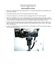
• Gain access to these switches by pressing the arrows on either side of the paper cover
toward the REAR of the printer. Then look inside to the right on the PC board. Compare the
settings to the table below.
•
Unless you are very sure of how to do it properly, contact VENDAPIN Support if you think
the settings are incorrect before attempting to change them. Just one switch in the wrong
position can stop all printing data communication between the two devices.
Printer Switch Settings
1
ON
2
3
4
OFF
OFF
OFF
5
ON
6
ON
LEVEL
ON
OFF
Computer Upload Problems
Datatron III Download Software
Follow the instructions on the CD to properly set up the computer to receive data from the
Datatron III unit.
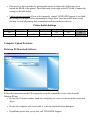
• Be sure the Com port number, baud rate, and parity are correct, as shown in the screen shot
above.
• Be sure the computer-style serial cable is correctly attached and not damaged.
•
If problems persist after you try this, call VENDAPIN Support.
Parts and Accessories
Replacement parts
The following is a list of replaceable parts for all Datatron III-based products from VENDAPIN.
Part
number
945884-001
Call
900001
900002
Description
Model 5884 Portable Serial Printer
DB-25M To RJ-11 Serial Printer Cable for Model 5884 Portable Printer
Printer Ribbon for Model 5884 Portable Printer
Paper for Model 5884 Portable Printer
770003 Test jumper plug for 9-Pin AMP interface Connector
645884-002 DB-9F to RJ-12 Serial Data Cable for Datatron III to Computer
Call CD - Datatron III ASCII Download (For attachment to a computer)
Replacement Control Card – Specific to YOUR system (Country and
Call
Location Code)
Call
Machine Harness – Specific to each copier – Call VENDAPIN Support for
correct interface
NOTES
NOTES
NOTES
Contact
Sales/Manufacturing:
21B Squires Street
Cortland, New York, New York USA 13045
Tel: +1.352-678-3021
Alternate: +1.607.428-0627
Fax: +1.775.514.7530
[email protected]
General Support:
Technical Service Support
[email protected]
Corporate Offices:
16381 Cherokee Road
Brooksville, Florida 34601
Tel: +1.352.796.2693
Fax: +1.775.256.6311
Web Site:
www.vendapin.com