1
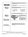
IMPORTANT MANUAL
Do Not Throw Away
Operator's
Manual
MODEL NO.
358.797161.32cc
Always Wear Eye Protection During Operation
L
WEEDWACKER
A WAR__ING:
2 Cycle Engine
®
b-_uelMix 40:1
ReadtheOperato_sManua_
and FoUmv All
and Safety Instructions,
FailureTo Do So Can Result
• Assembly
• Maintenance
• Operation
• Repair Parts
in Serious Injury.
Sold.by Sears,
5304167877-6-03/31/93
Roebuck
and Co., Chicago,
IL 60684
U.S.A.
© 1993, Sears, Roebuck and Co.
_ o_ Y_ r_o_d_,_
_W_.
_, ,+,is
w_k_e-
i__,,_i_.
m_,_.o_ ,u_,,p
_.d,.g
__
operating andmaimenanceiastruaionsin the oi_':atgr_ manual.Searswdl repatr _reeoi cna$fieany acmct in matena_
or Workmanship.
This w'arcatuyexcludes nylon fine. sparkplu_ and ali" cleaner which am expendable partsand become v,Oraduring normat use.
"
"'<::"
<_" = If the Wcedwacker"_ is used for commercial or-reataI purposes, this warranty does not apply.
WARRANTY SERVICE IS AVAILABLEBY CONTAC'I'IIqG THE NEAREST SEARS SERVICE CENTER/DEPARTMENT IN THE UNflED STATES. This warranty applies only while this product is in use ia the United States.
*_>.t
This warrant3' gives you specific legal rightS,and you may also have other rights which vary from state to state.
SEA_RS, ROEBUCK AND CO. DEPT. DISITWA HOFFMAN ESTATES, EL _0IY9
C>.t
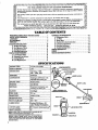
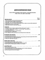
TABLE
WARNINGS AND SAFETY INSIRUCrIONS
KNOW X,DUR TRIMMER
.........
...................
: ....
3
GENERAL MAINTENANCE
.......................
A. Maintenance Safety ...........................
B, Air Filter ...................................
C. StarterRo_
................................
I5
[2-Cycle, Air-Cooled
Idle-
75oo
2500 - 3200
Sald State
Diaphragm
ENGINE
"OFP;i
All Positions with
............... adjustable fuel mixmrejets
Positive Switch
i Auto Rewind
MUFFLER:
[ Tempetmure I.,hmtiag(not spark
arre_g;
see Notice, V6)
CLUTCH:
FL1ELTANK:
17ft. oz.
SPARK PLUG:
71-858_ (O-14)
16
16
16
_7
D. Flexible Dfim Shaft La_brication .................
18
E. Carburetor Adjttsanents
.......................
19
E Gear Box Lubrication . : .......................
20
G. Trouble Shooting Omrt .........................
21
REPMR PAEIS LIST..-_
..........................
22
INDEX ............................................
25
QUICK REFERENCI_, PAGE ........................26
SPECIFICATIONS
o_-
_
o "_
OF CONTENTS
ASSEMBLY
.....................................
6
ACCESSOR!_
................................
.. 9
S'IX)RAGE .......................................
9
ENGINE INFORMATION
... ....................
:. 10
A .Furling Your E_gine. .........................
l0
B. Pre_tion
Che_
......................
... 11
C, Starting h-_ons
...........
; .........
.....
11
D. Op_rati_ Imstr_ctions .........................
12
USING YOI_ TI_MVIMF_ .........................
12
A. LineTrimmer
Safety ..........................
13
B, Automatic Line ASvanee .......................
13
....
C. Cutting M_ods ............................. 14
D. Line Replaeemeat
,
FOAMGRW
WARNINGS
.................
AND
SAFETY
INSTRUCTIONS ....
..............
•
_
i
i
....,
This tool can cause serious injury or blindness to the operator and others.The wamings and safety instructions in this manual
must be followed to provide reasonable safety and efficiency in using this tool, The operator is responsible for following the
warnings and instructions in this manual and on thetool. Read theentireOperator,s
Manual befnreassemblingand
using
this tool! Restrict the use of this power tool to persons who read, understand, and follow the warnings and instructions
in this manual and on the tool.
A DANGER
NEVER USE BLADES WITH THIS TOOL.
-- THE BLADE CAN COME OFF AND
SERIO USLYINJURE YOU AND OTHERS
-- THIS TOOL IS DESIGNED FOR
UNE TRIMMER USE ONLY.
A WARNING
THE TRIMMER LINE CAN THROW OBJECTS
ViOLENTLE
.
-- YOU CAN BE BLINDF..DOR INJURED.
-- WEAR EYE AND LEG PROTECTION.
HAZARD ZONE FOR THROWN OBJECTS.
THE TRIMMERLINECAN
OBJECTSVlOL_ENTL Y.
THROW
-- OTHERS CAN BE BUNDED OR
INJURED.
KEEP PEOPLE AND ANIMALS
30 FEET AWAY.
A
WARNING
-- FOLLOW ALL Wa,RNINGS AND
INSTRUCTIONS.
OPERATOR'S
MANUAL
READ --OPERATOR'S
FAILURE TOMANUAL.
DO SO CAN RESULT IN
SERIOUS INJURY.
SAFETY NOTICE
Exposure to vibrations ihrough prolonged useofgasoline powered hand tools could cause blood vessel or nerve damage
in the fingers, hands, and wrists of people prone to ¢irctdation disorders or abnormal smdlings. Prolonged use in cold weather
has been linked to blood vessel damageZm otherwise healthy. _ pJe.J(_3,mpt_o ms occur_is¢£h_!_mbncss._i_i'n,oloss
o[
strength, change in skin color or texture, or loss of feeling in the fingers, hands, or wrists, disco ntlnue the use of this tool
and seek medical attention. An anti-vibration system does not guarantee the avoidatg'e of these problems. Users who operate
power tools on a continual and regular basis must monitor closely their physical condition and the condition of this tool.
3
,,
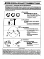
AWARNINGS
AND SAFETY
INSTRUCTIONS
im
.........
A
___-
II
__I
iiii
L _
I
ii
IIIL.
_.Jl
L .Mways wear a safety face shield or safety goggtes. See
_'Aecessories;"
&
1. Inspect the area to be cut before each use. Remove
objects (rocks, broken glass, nails, wire, string, etc.)
which cart be thrown or become ent,aagled in the trimmer head.
2. Keep hair, fiagees, and all other parts of the body
away from openings and moving parts. Air,rays wear
+ heavy, long pants, boots, and gloves. Do not go
barefoot or wear sandals, jewelry, short pants, loose
dottfing, or clothing with loosely hanging straps, ties,
tassels, el_. Secure hair so it is above slao_Aderlength.
Being fully coveted will help protect you from pieces
of toxic plants such as peison ivy thrown by the Trimmer Head, which could be more of a hazard than
touching the plant itself.
3. Do not operate this tool whenyou are tired,iU .or under
the influence of alcohol, drags, or medication.
4. Always use the assist handle. See "_.rnbly:'
A
2. Keep others including children, animals, _ers,
and hellxrs outside the 60 fcot'_
Zone. Stop
the engine immediately if you are approached.
3. Always keep the engine ou tim right side of your body4. Hold the tool firmly with both hands.
5. Keep firm footing ard balance. Do not over-reach.
6. Keep trimmer head below waist level.
8. Keep all parts ofyourbody away from thetrimmer head
and muffler when the engine is running.
6. Never start or run the engine inside a dosed room or
building. Breathing exlk.a,ast fumes can kill.
7. Keep handles free of oil and fuel.
9. Use only for jobs explained in this manual.
TOOLSAFETY
7tTBi_gffre--i]a-es_eld
A MMrO' A/ $Agg/T
1. Maintain the tool according to recommended procedures. Keep the trimmer line at the proper length.
2. Never start the engine with the clutch shroud
removed. The dutch can fly apart and cause serious
injury.
3. Disconnect the spark plug before performing maintenance except for carburetor adjustments.
4. Make_retor
adj__h9
us"
mg sup_tled top_ithe
trimmer line from contacLing any object. Hold the tool by hand; do not use the
optional shotflder strap for support.
5. Keep ot,hersaway when maki.ng carbtaetor adjustments,
is pmperiy_.
5. Useordythespecifiedtfimmerhead.
See"Specifications7 Makesare Ihetriramerhead is pmpeflyinstalled
and fastened. Refer to "Assembly:'
6. Use only genuinereplacement
6. Be sure the trimmer head stops turning when engine
idles. See "'Carburetor Adjustments.'"
7. Make cattxwetor adjustments with the drive shaft housingsupported top,vent thetrimmerline
fromcontacting any object: Hold the toolby:hand;_do,not use the
optional shoulder strap for support.
8. Keep odg_ away when rnaldng carburetor adjusanents.
9. Useonly accessories or attachments as recommended
for this toot by Sears.
& EiT/m
L Mix and pour fuel outdoors and where them ar e no
sparks or flames.
2. Usea container approved for fuel.
3. Donot smoke or allow smoking near fuelor thetooi or
while using the tool.
4. Wipe up all fuel spills before starting engine.
5- Move at least 10 feet away from fueling site before
.......
e.
6. Stop engine be[ore removing fuei _.
7, Run fuel out of the fuel tank before storing the tool.
+
' "
5. Wearhearingprotectionifyouusethistoolformore
than I_ hoursper day.
2. Replacetdmmerhihdpartsdaatareemcked,
ehipped,
broken,ordamagedinanyotherway beforeusingthe
tool.
3. Use only .080" diameter Sears Laser Line. Never
use wire, rope, string, etc.
•
-"
Z DO not raise the engine above your waist. The trimmer
head can come dangerously close toyour body.
1. Inspect endretool before each use. Replace damaged
parts. Check for fuel leaks and make sure all fasteners
.... are in place and securely fa.qened.
4
II
K Storetoot and fuel in an ;uea where fuel vapors cannot.
reach sparks or open iiame, from water heaters, electric motors or switches, furnaces, etc.
partsas recommended
bySears.
,A
TR.4NSPORTI_G
AND STOgAGE
L Hand carry the tool with the engine mopped and the
muffler away from y_ur Ixxly.
2. Allow the engine to cool, empty the fuel tank, and
secure the tool before transporting in a vehicle or
storing.
3. Before stodng th_ tool, us_ up fuel left in the carburetor by starting the engine and letting the engine runtmdl
it s_ops.
4. Store tool and fttel in an area where fuel vapors cannot
reach sparks oropen flames from water heaters, electric motors or switches, furnaces, etc.
5. Store the tool so the line iimiter cannot accidentally
cause injury. The tool can be hung by the drive shaft
housing or by the bracket below the engine.
..6+..Store-tooloat of+reac4aofchildren =_
[f si_a/ions occur which are not covered in thls rnanual,
use _
and goodjudgement. Contact your Sears Serdce
Center/Depar_ent
if you need ass_tance.
.,llL,i
i
I [
"
"
r
Illl II
I
IIII II
I II Illll
II
roll
,,,.,
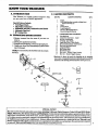
KNOW YOUR TRIMMER
ii
m i nl. ,.,.,
, ,,,,,.,,
,,
,.,
i
iii ii
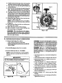
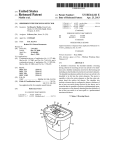
Your Trimmer is a versatile product designed to help
you give your lawn a finished appearance.
I
i I
ii
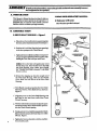
CARXONCONIXN'IS:
Engine
DriveS_
Box Assembly w/SafetyLabel
includes Dus(Cup (2a9
3
Shle!d
I
Trlrmner Head
-2-cycle F.atghaeOil
Operator's Mmual ('Not
Showa)
Loo_ PartsBag (Not ShovM)
1
!
1 .
I
*LOOSE'PAR_ _G
INSTRUCTIONS
I. Remove contents from the carton if you love not
done so.
2. Check parts against the list below.
.3. Examine parts fotdamage. Donotusedamagedparts_
4. NOtify your Sears Store immediately ff apart is missing or damaged.
NOTE: It is normal tohearthe fuel fdter rattle in anempty
fuel tank.
Q]_y.
I
2
4
5
---
" 18."Cutang Path .
UNPACKING
I
KEY NO.
Special Features Include:
* CentrifugalClutch
" AU-posifion Carburetor
* Adjllslable, anli-vibe, cushioned Assist Handle
- Automatic Line Feed
B.
i
c. TON
A. INTRODU_ON
I
I
"l
CONTE_S:
6
FlexShaft
Lu_
I
7
Slotted
4
Hex Head Screw - Shield
8
He.,x Nm, Assist Handle
1
9
T-Hardle - Assist Handle
I
I0
_qu_
1
U
12
13
HexSocket HeadScrew, Clutch Shroud
Hex Lock-Nut-ClutchShroud
Large Oap Washer
2
2
1,
14
Hex Wrench-Small
I
15
16
17
Hex Wreneh-Lavg_
Hex'Screw - Throttle Trigger Housing
Hex Nut - Tlnut_ Trigger Housing
I
1
1
I._ad SCleW - A._i_ }_mdte
*Hardware 'is shown in actual size drawings in the assembly
imtm_ons. Comparethehardwareinthe loose partsbagwith the
hardwarein the drawingsto dctermim fl_€correctlint to us_.
16
SAFETY LABE3L
10
6
15
_-2a
13--@
SPECIAL NOTICE
For users on U.S. Forest Land andin some states, including California (Public Resources Codes 4442 and 4443),Idaho,
. _in_%Minnesota,
New_J_
O_on,__d...Washington:.Certain
internal combustion.engines.operated
on-for,.st,
bmsh,
and/or grass-covered lands, in the above area_, must be equipped with a spark arrestor, maintained in effective working order,
or theengine must be constructed, equipped, and maintained for the prevention of fh-e. Check with your state or l_al authorities
for regulationspertainingto tI-_se requirements. Failure to follow these requirements is a violation of the taw. This unit is not
.fact0ry-equlp pod with a _
arrestor; however, a spark anes_r is _
able as an optiooal part. If a spark arrestor is required
m your area, order Part #952-701612 from your Sears Service Center/Department:
..............
iiiiiiiii
i
i1111111|1| i
I
72
I
i
i
IIII
I1_
II
IIIII
I
IIIIIIIIIIIIIIIIHIII
A. PMJ_ALATION
L _
This Oix:rator's Manual has been developed to help you
assemble the tool and to provide its safe operation. It is
important that you read the entire manual to become
familiar with the tool before you begin assembly.
........
B.
ASSEMBLY
1. DRIVESHAFF
I'OU[
OP_T01"S
MANNUAL
Tookyuwm
Hex Wrenches provided with tool
iiiiiiillt
I
........ "....
STEPS
HOUSING
-- Figure
1
DRIVESITAF'r
HOC_ING
a_
b,
Place the two Screws (from the loose parts bag) into
the holes on the Clutch Shroud as shown in Figure I.
Posifon the Lock-Nuts (from the loose parts bag)
in the hex openings in _e Clm_ Shroud.
GROOVE
c. "I_ghtenthescrewswith the small hexwrench provided just enough to hold the hardware togetherwhile
holding the Lock-Nuts with your other hand.
NOTE: Dirt on the Shaft will significantly reduce
the life of the tool. If the Flexible Drive Shaft falls
out of the Housing, clean, relube, then reinstall.
See-_Flexible Drive S_ Lubrication" in the Maintenance sectiom
d. Remove the shipping cap from the straight end of
the Drive Shaft Housing, Make sure the Flexible
Drive Shaft does not fall out of the Drive Shaft
Housing.
e, Turn Handle around and position the Drive Shaft
Housirig with the Arbor Shaft down _ shown in
Figure 1,
DRIVESHA_.
HOUSING
L Align the groove on the Drive Shaft Housing with
ihe Ridge on the inner lower wall of the Clutch
Shroud opening.
r
g. Turn theArbor Shaft as necessmTto align the square
end of the Flexible Drive Shaft with th_ square inside the Clutch Shroud opening.
h. Ftrmly push the Drive Shatt Housing imo lheClntch
...Shred untilit contacts theEoamGtip_ar is ,within
118inch. Figure L
i. Tighten the Screws alternately with the. small hex
wrench undl secu_'e.
!
i
l
t
!
I
@
Ftgu_
_
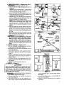
2. THROTTLE CABI._. _ F_u¢_
21 3, 4 & 5
|CAUTION:
[ Do out kink the throttle cable.
a. Slide the Throttle Trigger Housing away from the
Foam Grip.
NOTE: Before performing step "b'\ push the barrel
end of the throttle cable into the sheath until the barrel contacts the sheath. Figure 2 (in_t L
b. insert the Throttle Cable through the tunnel in the
Foam Grip until the end of the Cable extends at least
2 inches beyond the Grip. Figure 2.
• e. Hold the Trigger away from the Drive Shaft Housing
and inscrl the barrel end of the Throttle Cable into
the round opening in the Trigger. Figure 2.
When inserting the barrel end of the Throttle
Cable into the round opening in the Trigger, make
sure that the barrel is completely inserted and the
Throttle Cable ik located in the split in the Arm.
Figure 4.
d. Push the Trigger back into the Housing while guiding the Cable through the split in the arm. (Figure 33
Guide the arm into the Foam Grip tunnel while
re#acing the Throttle Trigger Housing flu_ against
the Grip.
€. Hold trigger agaimit the foam grip while in.fling the
, screw and nut. Do not install the screw unless the
.trigger is in the full throttle position.
]CAUTION:t
DO not overtighten screw. There must
be at [east 1/8" free play inthe trigger. Figure 5.
Make sure trigger will move freely so the trimmer
can fully return
to idle when the trigger
is
released. The trimmer head must not turn at idle
speed to avoid serious injury to the operator and
others.
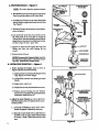
3.--AS_'D
LE _--Figures-6-&7
a. Be sure the Handle is positioned between the Safety
Label and the Throttle Trigger. Figure 6.
b. Push the lower end of the Assist Handle onto the
Drive Shaft Housing.:
c. Drop the threaded end of the square-head Screw
through the opening in the mp of the T-Handle.
Figure 7.
d. Pull on the threaded end of the Screw to bring the
square head of the Screw pest the pin inside the THandle. Figure 6.
e. Push the Nut into the hex opening .in the Assist
Handle and install the T-Handle into the round opening. Figure 6.
f. Tighten the T-Handle firmly by hand truly
4. SHIELD _ Figure 8
_k WARNING
Failure to install the shield in the position shown in
Figures 8 and 9 can result in serious injury to the operatot. The length of the shield must be aligned with the
lee.gth of the drive shaft h_h'_g. Direct the widest part
of the shield toward the engine,
C[CAUT][ON:]
The Hoe limiter {on the underside
of
7:- lhe_shieldt-is-sharpa
nd can-eat-you;
....
a. Remove
the packing cover and Dust Cup from the
Arbor Shaft. Figure 8.
b. Place the Shield on the Gear Box, aligning screw
• holes. Figure 8. lVlake sure the Shield is directed
Ftguge
Figu_
2
3
LABEL
T-flANDLE
t
Flgure
7
toward the Engine and is centered under the Gear
Bo_<-C--lamp:
c, insertthe
Ibur Screws (one at a time) through the
Gear Box into the Shield.
d. Tighten
the Screws alternately'with
a standard
screwdriver.
•
S.
HZAn -NOTE: _
S
Arbor Shaft has left hand threads.
@
a. Reinstall ate Dust Cupmatching the notcheson the
Dust Cupwith the splines on the Arbor Shah.
b. Install theGrassWasherover
the Arbor Shaft Malce
sure the Washer is against and curved over the Dust
Cup. Figure 8.
c. Thread theTrimmer Head onto the Arbor Shaftas
shown in Figure 8.
d,
Line up ate hole in the Dust Cup with the hole in
the center front of the Gear Box by turning ate
Trimmer Head. Insert the small hex wrench into the
aligned holes to keep the Arbor Shaft from turning.
See Inset, Figure 8. (inset. upper left).
e. Tighten the Trimmer Head against the Large Cup
Washer and Dust Cup while holding the hex
wrell_.
f. Remove the Her Wrench.
NOTE: To remove the Trimmer Head, insert the
hex wrenchinto aligned holes in the Dust Cupand
Gear Box. Unthread the Trimmer Head.
6.OPE TmGtmsmos a.
Before starting
the Engine,
9
stand as shown in
Figure9and_treek_f_ng
1.) Rightarm fullyexlended ,hand holdingthe Foam
Grip, fingers on Throttle Trigger.
2. ) Leh_
fullyextended, hand holding the Assist
3. ) Engine below waist level.
4.) Weight of tool evenly distributed between arms;
5.) Without operator heading over, the Trimmer
Head is aearand parTdlel to the ground and easily
contacts the material to be cut.
b. bdjth"t the Assist Handle up or down the Drive
Sha_ H o_sing (but above the Safety Label) toacomfortable position.
L
• • 1.).LoosentheT-Handle
By hand, adjust Assist
Handle. RetightenT-HaixUe by hand ordy.
2.) Rotateate Assist Handle left or right when itis
for cutting a large, sloped area such as a ditch
bank.
IPlgU_
9
I i
..
•
i II
Ill
.
Ulll n
"
II
....
A RIF
tllll
I
......
IUlllll
]l
The following accessories _re available through Sears Retail Stores. Catalog O_aflets.or Service Cenu_rs.
ITEM
S'IOCK
Safety Face" Shield .................................................................
Safely Goggles
2-Cycle Engine Oil ...............................................................
Spark Plug ......................................................................
Replacement Trimmer Head (available only through Sears Service Centers) ............
Replacement Nylon Trimmer Line
-- 400 ft ......
, ............................................
...................
--= 200 ft .........
_ ........................
_ ...................................
-- 100 f{......................................................................
Replacement Spool with Line
....
Shoulder Strap Kit ...............................................................
Spark Arrestor Kit .........................
•....................................
Flex Shaft Iad_ .., .............
............................
" ........
Operator's Manual ............................................................
•Awilable _magh
NO.
9-18613
9-1859
71-30143
?1-85854
530-094604
71-85778
71-85608
71-85771
71-85815
71-85783
952-701612*
; .... 530-030102*
...530-067877*
your SEARS Service Cenler/Galalegue..
G. STORAGE
It is important to prevent gum deposits from forming in e_sential fuel system parts such as the carburetor, fuel filter, fuel hose, or" fuel tank during
storage. Experience indicates that alcohol b lP.nded
fuelS (called Gasohol or using ethanol ormethanol)
can attl-act moisture which leads tOse-i_a-t_t_on
a--n-ffK_
formation of acids durlngstot-age. Acidic gas can
damage the fuel system of an englr_wh_e_
storage.
I. Allow the engine to cool, empty the fuel system, and
secure the tool before transporting or storing.
2. Before storing the tool. use up fuel left in Ihe fi_el lines
and carburetor by starting the engine and letting it run
until h stops.
NOTE: If you do not wa_nt to remove the gasoline
from your uniL SEARS CRAFTSMAN Fuel Stabilizer
(#71-33500) may be added to gasoline left in the tank to
minimize gum deposits and acids, if the tank is almost
empty, mix stabilizer With fresh gasoline in a separate
container and add to the tank.
ALWAYS FOLLOW INSTRUCTIONS ON THE
S_ABILIZER
CONTAINER.
TH_HEENGINE
AT LEAST
10 MINUTES
AFTER
STABILIZER IS ADDED TO ALLOW MIXTURE TO
REACH CARBURETOR. STORE UNIT IN A SAFE
PLACE. SEE STEPS 3-5 (this section).
3. Store tool and fuel in an area whe re fuel vapors canno_
teach sparks or open flames from water heaters, electric
motors or switches, furnaces, etc.
4. Store the tool so the line timidercannot accidentally cause
injury. The toolcan be hung by the drive shaft housing.
5. Storctool out ofreachofchildren.
9
ENGINE INFORMATION
,,
A. FUELING
1. FUEL
YOUR
,,
,
i
ii
i
|1
I
ENGINE
SAFETY
3. USE
a. Use only recommended
fuel mixtures.
b. Mix and pour fuel outdoors
and where
there are no spark8 or flames.
I PART OIL TO 40 PARTS GASOLINE=
3.2ft.
oz,oiltoI gallongasoline
8.0 ft. oz, oil to 2.5 gallon gasoline
Not all air cooled 2~cycle engine oils have the
same qualifies.
If SEARS CRAFTSMAN
2-cy.de engine oil is not available, use a good
quality, 2-cycle
engine oil recommended for
air -cooled engines. _JLx at a ratio of 16:1 (8 oz,
oil to 1 gallon gasoline). A 16:1 fuel mixture with
these oil.willassureadequate lubrication
for
your engine.
K Move at least 10 feet (3 meters)
away
from fueling
site before starting engine.
g. Step engine
before removing
fuel cap.
Allow engine to cool before refueling.
h. Beforestoring
the unit, use up i_ae! left in
the fuellinesand carburetorby startingthe
engine and letting it run until it stops.
i. Store unit and fuel in an area where fuel
vapors
cannot
reach sparks
or open
flames from water heaters, electric motors or
switches,
furnaces,
eta.
2. FUEL MIXTURE
THE FOLLOWING:
SEARS CRAFTSMAN 2-cycle engine oil mixed
at 40:1 is strongly recommended.
Consult the
instructions on oil container for proper mixing.
¢_ Use a conteiner
approved
for fuel.
d. Do not smoke or allow smoking near fuel
or tle unit or while using the unit_
_. Wipe up all fuel spills before starting
the
engine.
4. DO NOT USE:
•
•
NMMA Oil--National
Marine Manufacturers Association
(formerly BIA oil)-I)oes not have prover additives for ah'-ccoted,
2-cycle engines and can cause engine damage.
AIYrOMOTIVE
OIL--
Does not have proper additives for air-cooled,
a. Your unit is powered by a2-cycle
engine
2 -cycle engines and c_m cause engine ddmage.
which requires a fuel mL_ture of regular
Ak "CAUTION
unleaded
gasoline and a high quality enExverience
in_e__A_hLt
_c_o__
-b_i_e-eiF_lyomade._or_2--cyele_-air
.......
(called
gasohol
or
using
ethanol
or methanol)
cooled engines, The internaldesignof the
can attract momture
which leads to separation
2--cycle enginerequires
lubrication
ofmoving
and formation
ofaclds
during storage.
Acidic
parts.Lubricationis providedwhen theteeg_.. can damage
the fuel system
of an engine
•ommended mixtureofgesollne
and oilisused.
while in storag e . To avoid engine problems, do
b. Genitlne Sears 40.1,2-cyole engine oilis
not leave fuel in the unit when storing
for 30
days or longer.
Start the engine and let lt run
strongly recommended
for the protection
mttil the fuel lines and carhuretor
are empty,;
ofyourunit.Extensiveenglneeringtests
have
Use fresh fuel next season.
See the "Storage'
proven that Sears.2-cycleengine oilresists
section
for additional
information.
Never use
break-down at operating
temperaturescomengi'ne or carburetor
el e-aner products
in the
mon to 2-cycle engines; resulting in dependfuel tank or permanent
damage can occur.
.
able performance and 10nger engine life.
e. Gasoline
must be clean and not over two
months old. After a short period of time,
5. HOWTO MIX FUELAND
FILLTANK
gasolinewillchemicallybreakdown and form
Pour the proper measure of engine oil into an
compounds thatcausehard startingand damapproved, marked container.
Then, fdl the
age in 2-cycle engines.
container with regtday unleaded gasoline.
d. The correct measure
of gasoIine
to oil is
Iffuelisalready in the container, add the
very important.
Too much oil in the mixture
propermeasure
of engine oil. Then, dose the
willfoulthespark plug.
container tightly and shake it momentarily.
Too little oil or incorrect
oil
Do not mL_ ga_o!ir_ and o_ dir_t!y in th_
will cause e_ne
to overheat
and seize.
e. Always mix the fuel thoroughly
in a container since gasoline and oil do not readily
combine. Do not mix gasoline and oil directly
: in the ftii_:ii_.
,I0
.__
................
fuel tank.
b. Using a spout or funnel, fill the fuel tank with
fuel mix.
B. PRE_PERATION
_dew
sU Wm_s
Betore operat_
CHECKS
and Sd_
AWA/LNmG
_
fions." Make sure the trimmer head Is properly
Iilsmlled mid tmcu_ fastmed, Rffcr to "Assembly7
_ _:
6. se sure trfnmmrimd aOl_ turntngwSenmOm
t
your tool, _wa_:
7.
houangml_Oaed to_t
I. Inspect the entire tool before each use. Replace
dsm_ed parts. Check for fuel leaks and make sureall
f_lr_rs arc in place and securely fastened.
8.
Keep others
aajustment_
9.
Use-only accessories or attachments
mended by Sears for this tool.
Laser Line. Neverues
10.
4. Use only with the shield properly attached.
Nil I ,
II, I,,I
Jl I I ,,
C_ STARTING
INSTRUCTIONS
LSdorc, r
J
,
I
I Il
Ill
IN
the trimm_ linefrmn
omdacting tmyobjoct, Holdthe tool by band; do not
use theoptional shoulder strap fOrsupport.
2. Replace trimmer head parts that are crocked,
chipped, broken, or damaged in any other way
before using this tool.
3. Useonly ,080"diameterSears
wire, rope, string, etc.
Idles, See "Carlmretor Adjumnea_:'
Make_xb_r
a@tstments with the drive shaft
I
when
making
carbuggtor
as re_m-';
Cteantbeair£dterifd_rtybeforeoperatingthetool,
Ref_ to" Specificauons,
" .....for air filter location.
J t;
i illllll
(For location of controls,
away
roll, i
.G.tlI
.
! i
.
.,ll
refer to"Specifications._
me e.
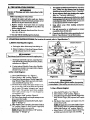
a. Fuel engine. Move 10 feet away.from fueling site.
b. Extend 4-6 inches of Line from Trimmer Head to
pro.ride adequate load on the engine.
I "lhetrhm_r
& WAnNInG
hess!lwl/t
turn _ s_n_ ti_ engh_ st_t_.
Figure
XO
e. Rest Engit_ art Shield _n ground, supportirtgTrimmer Head off the ground away from trees, bushes,
-or__Figure-10:
d.
If usingoptional Shoulder Strap, place Shoulder
Strap on }_urshoulder. Start engine b_re clipping
Shoulder Strap to the tool.
2. For a Cold
Engin¢_
a. Move OrdOffSwitch to ,on:' Figure IL
b. Move Choke to "'full" position, Figure 12.
c. Grasp Foam Grip and squeeze Thro(tle Trigger fully
I_ep Throttle Trigger fully squeezed until engine
runs smoothly (through step "g").
d; Pull Starter Rope sharply anal engine attempt_ to run.
bttr no more than 8 pulls at full choke to avoid flood*
ing the engine./'he engine "attempt to run" may be
hard to hear. The operator
must listen earefuUy.
After 8 pulls, proceed to step "e.'" even if engine has
not _ttempted
to run.
€. Move Choke to "'half' position, Figure 12+
f. Pull Starter Rope sharply until engine attemps tonm,
but no mo,m than 5 pulis.
NOtrE: Ifen$ineha_ nois_a_ctaft*rSpulis, repeat
s,_ps-_" through
"f:'
g. Allow engine to run 5 seconds,then move Choke to
• squeezed untilengine runs smoothly
NOIX: Ifengir, e dies with C_okeat "off" position,
rq,eatsteps"e"thto_ "'g:"
Avold anybodily contact with the m_when
AW_t.m_G
starting
[
a warm engine. A hot muffler can cause serious burns..
:3. For aWagtn
Engtne:
a. Move OrdOffSwitch to "on." Figure 11.
b. Move Choke to "'half" position. Figure 12.
c. Gt-asp Foam Grip andsqueeze TarotdeTrigger fully.
Keep lhrottle Trigger fully squeezed until
engine
t_nff.
d. Pull Starter Rope _harply until engine rum, but
nomore than 5 pulls.
NOTE: Ifenginedoes n0t run afterSimlls, idsprocedurewith Choke at "oW' position. Figure 12.
e. MoveChoketo"otT'position.
Figure_..KeepTrfg,
get fully squeezed until engine runs smoothly.
I1
efl'ud}:
a. Rdaelengine.
Mdve lO feaaway from fudingsite.
b. Move On/Off Switch to "on:' Figure I1.,
c. Move Choke to "full" position. Figme 12.'
d.G_ Foam
Grtpa__
L Move 0_
5 pulls./_o rd_er_ys_e_dunti/en_
Thro_eT,
igg_r
my.
Keep Throttle Trigger f#lly squeezed._l
to "off" po_don, Figure 1.2..
r_
smoo_.
NOTE:Xfe_ae hasnocsma_, paUSta_P, ope
engine
5 more palls. Ifengi_ still does not run, itis probably flo0ded. Wait a few minutes and n_at in_
€. Pull StarterRope sharply untilengine attemptsto
run, but no more than 5 pulls.
cedure with Chokeat "off" po_on.
i
m,,,,,,,,,,,
III
mm
m,
Fgur¢ 12.
P
II
I
,,,,.,,,,,,
Jill I
'
,,
D. OPERATINGINS'gRUCTIONS
I. Before entering the material to be cut, bring the
engine to cutting speed by squeezing the throttle
2. Always rel_se the Throttle Tiigger and allow the
enginet0retaratoidtespeedwhennotcat6ng.
tl"iggeK
a. Do not run the engine at a higher speed than
necessary. The cutting line will cut efficiently
3. Makesurethe Trtmm_Headsto_ mn_'_ea
the Thro_ liigger is rdeased and the eagiae
when the engine is van at less than full _x_ttle,
At lower speeds there is less engine noise and
vibration. The trimmer line _
last longer and
will be less likely to "weld" onto the spool.
runs at idle speed. For correction refer to "_.at_-
w.lor Adjustments:"
4. To stop the engine:
b. If the Trimmer Head does not turn aben the
engine is accelerated, make sure the Drive Shaft
Housing is propedy seztcdin the Clutch Shroud.
.Refer to '_.ss_mbly-Driv¢ Shaft Housing7
,,,,,m
, ,,,
i
USING
IIIIIIIIIIIUIII
J
I
YOUR
II
,
mmmm,m,,
m,
I
,H
a. Relea_ the Throttle Trigger.
b. Move On!Off Switch to the "OiT'
Figure 11.
, J,,'
position.
'
TRIMMER
lllll
l
l
l
l
III
llll
AW amsG.- ows
The rapidlymovinglin_causesobjectstobcthrownviotcutty.
The shield will not pt'ovidc complete pr0tcction to the operamr or others. The operator must were"a safety face shield
or goggks, Always wear heavy, long pants and boot_ Keep
others at least 30 feet away.
.£t WARNING
l.e
,,1,
,- _ZONE
This tool will throw objects aad cut. Keep others including
children, animals, bystanders, and hdpers at least 30 feet
away from the operator and tool. Stop rite ehgine ifyou are
approached.
WARNTNG
--
.... T_+_+E._.p_..+++
.._+.
+_,
_._._:g1,.+b+m_+m.+or
damagedtaanyo_r.rw_ycaaflyaparta_lcaus_s_ri_tsinjaryo
Trimmer Head
,Use Oaly Genalne Rephcements Parts
Do not use. Throw damaged partsaway.Replace damaged
parts beforeusingthet_ L
i
i
A. LINlg TlglMMEIg
!ll :iL_, _
I
i
..........
i
! !
' !'!,
'',,,I'I'I'.,,, ,
$_
L OP .TOI
J
a. Always wear a safety face shield or goggte_, See
"Accessories;"
d. Make sure the trimmer head is properly imtalled
and securely fastened. Refer to "Assembly."
b. Keep hair, fingers, and all ether parts of the body
away' from openings and moving parts. Always
wear heavy, long pants, beets, and gloves. Do not
go barefoot or wearsandals, jewdry, short pants,
loose clothing, or clothing with loosely hanging
straps, ties, tassels, etc. Secure hair so it is above
shoulder length. Being fully cg_;et_l will help protect you from pieces of toxic plants (such as poison
ivy) thrown by the.Trimmer Head; which could be
more of a hazard than touching theplant itself.
e. Be sure the trimmer headstops tm-ning when the
engine idles, See "'Carburetor Adjustments.*'
f. Make carburetor adjustments with the drive
shaft housing supported to prevent the trimmer linefrom contactingany objecLHold the
tool with 3_mJrharfl; do not use the optional shoulder strap for support.
g. Keep others away when making carburetor
adjnslmen_
h. Use only accessories or attachments as recommended for this tool by Sears.
c. Do not operate this to01 when you are tired,
ill, or under the influence of alcohol, drugs,
or medication.
3. tr[rr//NG
d. Do hot swlng the ualt withstw_hforce that you are
in dangeroflosing
your balance.
a. rInSp_'t
_
usP_ _[[love
or beco,-m_ entangled in the
_-Useo_fo_jobs_xplain_naL
s--au-'_Idis properly-_t_:
iii i
iii
i ii
i
]l
LINE ADVANCE
itt _
ii ii i ii
_kWARNING
a._d_iir_
o The line will wear f_
and will advance more frequently when cuttiagagaiust hard surfaces such as
rocks, bricks, concrete, metal fences, etc., than when
cutting against woody objects such as trees or wooden
fences.
•
b_
b. Always keep the englne on the right side ofyour
body.
c. Hold the tool t'wndy with both hands.
d. Keepffu-m foo_and
balan_ Do notover-teach.
e.. Keep the trimmer head below waist level.
L Do not raise the engine above your waist.
g. Keep all parts of your body away from tl_ trimmer lhte and m_
when thee_is
rmmlng.
b. Use only.080" diameter Sears Inset Line. Never
use wire, string, rope, etc.
• The trimmer line advancesautomatically
wears and reduces the cutting path.
_o he cm
whie.h
canbe th,'v_
a. Inspect the entire tool before each use. Replace
damaged pants. Check for fuel leaks and make rare
all fastcmrs are in place and securely fastened.
18. AU1X_I_4tATIC
ar_
trimmerhead.
2. TO0/.
c. _he
[he
objects(Rxks,hx_m g_;s, mi_, wir_ s_,g, _)
c. Never _xt or run theeaglne insidea dosed room
or buildin_ Breathing exha,,_ fum_ can kill.
f. Keep handles free of oH and fuel.
Ifiine does not advance properly:
-- Operate the engine at full throttle and allow the line
to strike a hard sdrface such as concrete or the
ground.
Use only DSO" diameter laser Line. Other sizes of
line _ill not advance properly and can cause serious
injury. Do not me other materials inch as wire, strin_
rope, etc. Wire can break off during cutting and
become a dangerous missile.
AW_G
Use minimum speed and do not crowd the line when
cutting .a_mmi hard objects (rocks, gravel, loose object_
etc.), which can damage the trimmer head, become
entangled in the line, or be thrown causing a serious
hazard.
CU'ITINGUNE
UNE LIMITER
Hl_aeis 4"or less, stop theeagine and cheek for _ae
binding or tangling on the spool. See "Trimmer
Head"inthe
MaimenanceSection
for rewinding
insmlctions.
a Ah_ayskeeptheshidd in ptaeewhentheton isbeing
operab_L Figure13.
rtt_
xa
_3
N.NI Hl l HII
¢. ¢uTrmG
•
IT,I
I
I
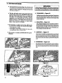
Thetipofthe line does thecutting. Youwill achieve the
best performance and minimum linewear by not crovdmg theline intothecutting area. The right and wrong ways
are shown in Figure 14.
• The line will easily remove grass and va_eds from
around wars, fences, trees, and flower beds, but it
also can cut the tender bark of trees or shrubs and
scar fences. To avoid damage, especially to delicate
vegetation or trees with tender bark, use less than full
throttle and keep a 3 inch distance away. Keep in mind
that the line will advance suddenly io a longer length
when it wears downto-4-Sinches.
e
II
II
Im_rHoiw
For wimming or scalpinguse
less than full throttle
to prevent line breakage and excessive line usage:
•. during light duty cmIing.
-- near objects around which the line can wrap, such
as small posts, trees, or fence wire.
• For mowing orsweeplng, use full throttle for a good
dean job.
Always _ear ¢yt pmtecCon. Neverkan o_a- the trin_
met head. Rocks ordd_can
rtmc_orbethnm, n imo
&waaamo
eyesand _ceand causebSndaessm-otherseriousl_u-y.
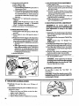
x.
!
r a,e xs
Hold the Ix_onlofthc tzimmerhead abo_3incl'esatx_
above thegnmnd and at anangle. Allow onlythetip of
the lineto make contact. Do not force thetrimmerline
intothe work area.
2. SCALPING -- Figure 16
The scalping techniquereraovesunwantedvegetation.
Holdthe_xtom ofthet_ner head about3i_mhesabove
the ground and at an angle. Allow the tipof the line to
strike theground around trees, posts, monuments,etc_
This technique increases line wear.
3.
MOw---iNG ,- Figure 17
Yourtrimmeris idealformowinginplaces ooaventiona!
lawnmowerscannot reach,la themowing position, keep
thelineparallel(otheground.Avoidla-essingthehead
hRo
the ground as this can scalp the ground and damage the
tool.
4. SWE mG-- rg,urexa
........
_fanaingaction_ea_g-linecanbeq_-for-a
qttickand easy clean up. Keep the lirteparallel to and al:_e
the surfaces being sweptand move the tool fromside to
side.
Irqm_ 14
•14
-
ii
•
_ iiiiiiiImllll'HII
-
IIII
• Fer preper llne feed:
--Use only genuine Sears pre-wound spools and
.080" diameter Sears I_tser Line brand line.
Use of other types of spools or lines can result
in excessive breakage, line welding and improper
line feed.
-- Pre.wotmd spools offer the most convenient
method for replacing line as'well asoptimumpcrformance.
vl_,ttt_ _
• Always ckan dirt and debris from the spool and hub
•when performing any type maintenance.
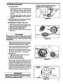
1..lln._fln_
NeW
Spool
with
Line
a. HoldtheTtimmerHcadasshowninFigurel9.
Press
the Lock Tab and turn Cover cotmte_cloc_wis¢.
b. Remove the Cover and Spool. Figure 20.
c. Clean dirt and debris from all parts.
d. lnspectail TrimmerHeadpar_ fordamage, Replace
d_aged parts.
[Trimmer head parts that arecltipped, cracked, broken,[
[or _
in any ether way can fly ap_t and cause[
Iseriousinjm'y.Donotuse.Replacedamagedlna'tsberore
/
]usitag the tool.
[
e. Insert about 6 inches of-Line from the inside6f_he
Hub Ilwooghthe Line Exit Holeto theoutsideto_eep
--lhe--L__kF
"glill-ffth'_head. Figure 21:
f. Route the Line behind the Balancing Pin (Figure2l)
while carefially p!acing the Spool in the Hub.
_g. Pull on theLine e.x/ending outsidethe Hub to make
sure the Line will not ad(ance. See Inset, Vlgur_21.
This indicates that the Line is routed properly.
h. Reinstall Cover:
L).Atign the four catches on the Hub with the cutouts in the Cover. Figure 20.
2.) Press the Cover onto the Hub.
3.) Turn Cover clockwise. Figure 19_i. Check to ma_
sure all four Catches and the Lock
FlgUl_
21
Tab are properly _sw.aed as shown in Ftgure 22, lhen
test the Cover by trying to ann it counterclockwise.
j. Pull on the Lineagain from outside the Hub. It the Line
can be pulled from theassembled head, it is not properly
routed arotmd the Balancing Pin and willfeed continuously when the Tri0amer Head turns. Remove
Coverand re-rou_teLine_s shownin_Figure 21.
•A_ f_ar _l_sm_t
be f_tmedan_l
theto_ t_ _
onto th_x_r,
ffh_dl_
hnpmi_rl_, _ _ver _m ll_
ell'and bevomea _
miss_
LOCK TAB
rlgu_
i5 •
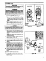
a. Follow "hstalling Spool wiI.iac;' st_ "a-d" and.i
remov¢ any Liac retaining o. the Spool
b. Use a 40 foot leagth_.080 "diamca_Sca_l.ascr Line.
c. Insert V16"to l/8"oftheend of the Linethroogh one
of the holes in the rim of the Spool. Allow no more
than 1/8" Line to extend beyoad the rim to avoid
interference with line release action. Figure 23.
d. Wind the Line onto the Spool in the direction shown
,Does not aa_mme, or breaks while eutting
-- Improperlymo_cdin head.
-- Improperly vamadonto spool.
-- Line size incorrect.
-- Too tittle line _tside
head.
• Weldsonto spool
-- Line size incorrect.
-- Incorrect spool.
by thearrowon theSpoolandastightlyandevenly
-- Cromtiag lin_ against material being ca.
-- Cuttha$at higher speeds thaa necessary.
as possible so the Line will feed ptx_pedy.Figure 23.
I ¢adfflXOX: ITheTrinmaer Head willm_mcfion
-- Wound loosely on spool.
properlyifthespoolisl'dled beyond thenmrA_
around the oaLside edge oCthe spool
• Rd_
continuously
-- Woundbeyondn_hes on spool.
-- Improperly roc_l in head.
-- Line size inconcct.
e. Follmv"InstallingSpoolw/Line" steps "€-j:"
-- Shield installed improperly.
o Usage is excess_
-- Improl_ly ro_-_t in head.
-- Line size incoming.
--Cutting at high gzeds around hard objects.
-- _
line agaimt material being cut.
• Pulis back _
NIgure
_d
-- Too tittle lin_ c_._de of head.
23
ilml
omsma. . MAmr u cz
n
.
UIIIIIIII
A. _ANOg
.
SAFE'rY
I. Maintain the tool according torecommended proeedures. Keep the trimmer line at the proper length.
_Ne_r-start-the-eaglae-wah-the_utch-shroud
tamaoved. The clutch can fly apart and cause serious
injury.
3. Disconnectthe spark plug beforeperfotmlag
maintenanee_cept for carburetor adjustments.
4. Make carburetor adjustmeats with the &iveshaft
housing supported toIa,evem thetrimater line from
cOntacting any object. Hold thctoOl with your hand;
.. do. not use the optional shoulder strapfor support.
5. Keep others away when making carburetor
adjuo-_anents.
nl
6. Be sure trimmer hera stops turamg
idles. See "Carb_tor
engm
_djustmcnts7
Useoaly _0_0"dian_r
Sears Laser Line . Never
use w_re_rope , smrg: _i
Replace trimmer _e_.d parts that are cracked,
chipped, broken; or damaged in any other way
before using the to_L
9. Use only genuine, cp_xcement parts as recommended by Sears.
.10.Iaspectretiretool I_.epi_ce
damaged
part_Checkfor
fuel.lea_. Make sure _._tfastenersare in place and
securely rasterS.
B. AIg_
i Adiny air filterdecreasesthe
lifeandperformance oflhe
engine and increases fuelconsumption.
Clean the Air Filter:
o .AJw_,safter StanksoffuelorS hours of operation.
ivhlcbever is less.
o More frequently in dusty conditions.
L _
_ two Screws _ the Air VL_r Cover
enough
to remove the Cover from tim Engin_
F'gure 24.
2. Remove the Air Filter from theCover. Figure25.
3.: W_li Filtc_iti S0ap_
_f.-
4. Squeeze Filter dry and replace in Coz:r.
16
[CA_JTtOIq: IDo not clean the air fdter in gasoline
or other flammable
solvent to avoid c_ing
a
fire hamrd.
5. R_iasmll
_'_Air
Fdt_C_r, makiagsat€the
Chol_
ExitSl(x(Fgure LS),_sp_x_doverthe Chol_ Lever.
LcAunoml
Make_.m_air
f_ris _*i_
the_
ofthe c_
_ _pdust
titan entering theen_ andca_
_
dama_
............
......
i ill
C. STARTER
ilUl i i
iiiii i
.H i
I
i
ii ii
i
" ,m_
I
i i i i i
i
,,H ,i
•....
_
i
i
,,
_
i.
7:
"-
, .11
Nevers_mm_e ene_
i clutch
, ,_,
ROPE
_h _e c_ch sh_.td_'
l_t fly apa_ _
The
cause se_,ous _ju_.
i1,1
ttt_OVE _
F
Do not remove the retaining tab and screw to remove
pulley. The spring beneath the latlley is under tension
attd can fly out causiltg serious kOury. Ifany part of the
ptmeyhomlagassemblyis
dmagedeaterthantherope,
do not use thetooL Take it toyour Sears Service Center.
1.
Disconnect Spark Plug Wire_Figure26.
2.
Remove the Screw and Nut in the Throttle Trigger
H_msingas ,J_m in Rgure 2. Hold the "[h[_e Trigger
away from Drive Shaft Housing and remove Throttle
Cable from Trigger, Pull Cable out of Foam Grip
runnel.
3.
Remove the four Ciutch Shroud Screws as shown in
!
Figure 261with thesmali, hex wrench provided,
4.
Separate the Clutch Shroud from the Engine. Figure 27.
l)t'i_
witho_
Shaft
S_.
ford_u'Ity.
A. _NaJm
F_m_27
Uxe only a hand tool to remove the clutch. Do not use any
type of motmize_ tool or _ike _zeclu_ in m_y way. Other-
5i Hold the "Flats" of the Clutch (Figure 27) with an
atljustable wrench as shown in Figure 28 (inset) and
remove the Nut _ntea-clcckwise
with_
...................
wrench.
NOTE: Clutch will slideofftheclank_haR
nat disassemble clutch.
6.
Remove the Beveled Washer, Clutch, and Large Rat
Washer as shown in Figure 28.
7. RemovethePulIey
&
9.
.
intact. Do
Housing fromtheEngine.
Figure28.
Remove Rope Retention Screw. Remove any remaining rope.
eULLEY l lOUSING
Hold Pulley Housing and hand turn the Pulley clockwiseas far as it willgo. Then, turn the Pulley counterclockwise until the Pulley Notch is aligned with the
Housing Notch nextto the Retaining Tab and Screw,
Figure 29, Next, turn the Pulley one complete turn
cotmtercloekwise until the notches are aligned again.
10. Insert the small hex w_nch into the hole formed by
the Notches to hold the Pulley in position. Figure 29
(Inset).
11. Use a 42" length of replacement
LARGE
FLAT
WASHI_
Rope.
,12., Movea_ray(10feet)fromthe,fueltank-withthe
replace
' merit Rope. Use a match and melt both ends of the Ro_
to prevent fraying.
rtgure_
17
13. Pull the melted ends th_ugha thick, cleantugwhile
the Rope is still hot to ob_n smooth, pointed ends.
B. Insert one end of the Rope through the Handle and
secure with a knot.
.,
15. In--r( theother end of the Rope through the Rope Exit
Hole, intotheinsideoftheHousing,
intothePulley.
and up through the Pulley Hole. See Inset, Figure 29.
16• Wrap Rope counterclockwise around thePulley Ratdaet
and tuck loose end under Rope where it comes eUl of
the Pulley Hole• Leave a l-inch tail laying fiat on topof
the Pulleybetweea the _lainer Rib andthe RopeRe_.ntion $crew/Posk Figure 29.
IZ Reinstall the Rope Retention Screw into the retention post. Tighten until snug.
NOTE: Do not ovenighten the Screw. Overtightening the screw can cause the threads in the screw post
to strip out.
18. Hold Rope taut at Rope Exit Hole so it will not move
and remove hex wrench.
19 Slowly feed rope into the Pulley Housing.
20. Make sure Spacer is in place as shown in Figure 28,
then reverse, steps to re-assemble.
IOttrrm_:!
Whenramta!ting the dutch, tightea
the nut just until the beveled washer is flattened
agalnst thedutch. Over or under tightening the nnt
can cause engine damaage. •
......
10111
FI._'_t_tL_.
D.
DRIVE
ii
SHAFT
"
.l
i
LUBRICATION
@ l_bricate the Flexible Drive Shaft:
After each ten (10) hours of operation.
----l__e_et_
:
has_
forg0
days or longer.
e Use the following procedure for best results:
e Use Flex Shaft Lube Part No. 530.030102,
NOTE: A tube of"Flex Shaft Lube •"has been supplied
with your unit to be used after the first 10 hours of
operation.
lfenginebasjust
beenope_ated , avoid touching the tourtier. A hot muffler can cause serious burns.
Lay tl_ _ble
dri_shaft on a clean surface. AvoidlaTing thesE_
on the floor, gronnd,oron
-any_t-nmy-h._eo
dir t-e r_
a f'_wiping the shaft, g_:_e _._._iduecan pick up dirt partides that can caus_ ¢_,_¢ge or premature failure,
[caxrrto_
Take ca_ _, zvoid injuring your bands
and fingers with br_k_'_ wires when checking for
damageor w_pmg lh_ __c._._e drive shaft, A cloth will
not prevent the 1:4"oken_
from puncturing or tearing 3our skin,
1. Remo_GearboxC[_
Figure 30.
_crew and Locating Screw.
2. Remove_theDriceSh_f_[_ousingfrom
the Gear Box.
3, Remove the Flexible L_z_,e Shaft from the Drive
Shaft H(msing. F_gur_ 3i.
4. Check the FlexiMe I_rSve Shaft for broken wires,
twists, or kinks aml _ep_ce if damage is found.
5. Using a clean cloth, wipe €he surface of the Flexible
Drive Shaft thorou#_y _<;remove any old grease.
6. Apply a uniform coat _f _t_beto the entire surfac_ ofthe
Fle_ble Drive Shall
7. inject the remainingco_t¢ n_ ofthe tube into the top of
the Drive Shaft Hca_s_ng.
& Replace Flexiblc _,_v¢ Shaft in the Drive Shaft
.........................................
18
r x-€
30
ms tre 31
9. Reassemble the Drive $_f-_ Housing and Gear Box.
T'ghten Screws s_y.
i i
Ill
I
II
E. __R
.
,,,
,
2
2. lht_SlC CJkKBURETOK
• This is a complicated task. It is important to follow
instructions in sequence as indicated.
i
I
" I
II
Aw umCG
housing supported to prevent the trimmer line from
contacting any "ob_
Hold the tool with your hand;
do not use the optional shoulder strap for sapport.
A W.4d_NING
away when making
SETTINGS
NOTE: In most cases,your engine can be made to
run properly with minor carburetor adjustments.
Refer to "T[ouble Shooting Suggestions" in the left
column for the condition you are experiencing and
follow the instructions. The basic carburetor settings
are provided in case they are required.
Makecarburetor adjustmentswi_ the drive shaft
Keep others
adjus_nents,
"1
AOJO_
carburetor
"- :-Ji
a. Turn the Low Speed Mixture Screw and the High
Speed Mixture Screw (Figure 32) clockwise until
they stop. Do not turn thescrews until they.are tight,
as damage to the needle seats can occur.
b. Turn the Low Speed Mixture and High Speed Mixrare Screws one full turn counterclockwise.
Serious injurytotheoperntorandothers
can (_xurifthe
carburetorisnolproperlyadjusted,
i
• Poor engine performance can be a result of other
causes such as dirty air=filter, carbon build-up
on muffler outlets, etc. See "Trouble Shooting
Chart"
before proceeding
with carburetor
adjustments.
o The carburetor has been _re.f_y
adjusted at the
factory. However, the openttor must be sure that
adjustments are made when any of tbe conditions
: o_aw as mentioned in "lX,ouble Shooting Suggestions" below.
0' _erv small adjustments can affect engine performance. It is important to turn the screw a verysmail
:-_-.amount per adjustment and tes_ performanc_ before
_g-fmther_
.
o
.
"d
"be no more than the width ofthe slot in the adjusting
SCreWS.
1. TROUBLE
SH(X)TING
SUGGESTIONS
_ Engine will not tontine to runat idle [msitioa.
See "bY Idle Speed Adjustment"
and "e. Low
Speed Mixture Adjustment:'
3. PROCEDURE
_. PF.EP.#.K&'rloN
!. )Osea fresh fuel mix. See "Fueling Your Engine:"
2. )Make sure the line extends to the length allowed
by the line limiter to provide correct load on
engine.
3. )Startthe engine. Cut grass for3 minutes to warm
engine. The engine must be at operating temperamre before carburetor adjustments can beper-
__foxed _o,'_ab:
4. )Stop engine and remove air filter by puUing it out
with _ur fingers. Refer to "Specifications" for
location.
t_ roLE STEED ADJUSTMEST
I.)Allow engine to idle.
-- Trimmer Head continues to spin when the engine
idles. See "b. Idle Speed Adjustment" and "d.
Deceleration Check."
.
c. Follow instructions "'a.Preparation:" through "f.
High Speed Mixture Adjustment:"
2.)Adjust Idle Speed Screw (Figure 32) until the
engine continues to run without stalling and
without the trimmer head moving.
-- Turnserewcloc_etoincreaseenginespeed
if the engine stalls or dies.
Fatgine dies or besitates when it should accelerate.
See "c. Acceleration Check"
-- Loss of cutting power which cannot becorrected
bycleaningtheair
lrdter.See"f. HighSpeed Mixlure Adjustment:'
-- Turn screw counterclockwise to slow engine
down and/or to keep trimmer head from
mrning.
Engine does not return to idle from full throttle
within 2 seconds. See"d. Deceleration Check."
3.) Follow instructions in "c.Acceleration Check"
and "d. Deceleration Check:'
4.)No further a_ustments
Eng_
w_Jl not run. See "Trouble Sh_.fing
Chat'L" Then, ifthecarburetor requires adj'ustment, beginwith"2. Basic Carbu_tor
Setti.gs."
if performanceis satisfactory.
[-......
I The trimmer line willbe spinning during most of this |
] procedure.Wearyourprotectiveequipmentandobserve
/
Iall
instrnc o.s.
are necessary ffthe
trimmer head does not turn at idlespeed and
]
.Lk.WA_I[N
G .......
:....................
[ Recheck idle speed after each adjustment.
The trimmer
] head must not turn at idlespeed to avoid seriousinjury
to the operator and othem
19
A.'l,.qi,.l=,,_
J'-ili,dlillitit_l
I,,71"1
II,,_idli_
l.}Altow engine to idli_.
2.)Squeeze Trigger hilly
a. If p_rformance issatisfactm_,
Deceleration Check:
r- Low i_'_;D MIXTUItJg ADJUSTMENT
i.)Ailow engine to idle.
2:)Trim the LowSpeed Mixture Screw (Figure 32)
slowly clockwise until the speed starts to drop.
" Notethis positio,.
3.)Turn the Low Speed Mixture Screw counterclockwise until the speed increases and then starts
to drop again. Note this position.
4.)Set the low Speed Mixture Screw at the midpoint between the two positions.
5.)Follow instructions in "c, Acceleration Check"
and "d. Deceleration Cheeky
proceed to "'d.
b. If the enginedoes not accelerate smoothly,
turn the Low Speed Mixture Screw (Figure
32) .counterclockwise a small amount (no
more than the width of the slot in the adjusting screw.
3,)Repeat step "2.1"" until smooth acceleration is
obtained.
NOTE: It may be necessary to repeat "b. Idle
Speed Adjustment" through "'c. Acceleration
Check," to obtain correc t adjustments.
4. )Follow instructions in "d. Deceleration Check:"
d. DECELERATION
f. IlIGH SPEED MIXTURE
ADJUSTMENT
Do not operate engine at full
th.q_e for prolonged periods while _
high
speed adjustments as damage'lo theengine
CHECK
cau o_'Uro
l.)Allow engine to id!e,`then squeeze Throttle Trigger fully.
2.)Allow engine to run at full speed for about 1
second.
l.)Suppon the drive shaft housing so the trimmer
line is offthe ground and will not make contact
with any object.
2. )Allow engine to idle, then squeeze Throttle Tl'igget hilly.
NOTE: Perform steps "'3.)" through "5.):"
at ball throttle.
3])TurnHigh Speed Mixture Screw _gure 32) very
slowly clockwise until engine speed is reduced.
4.)Turn High Speed Mixture Screw very slowly
counterclockwise. Stop when the engine begins
to mn roughly.
5.)Turn the screw slowly the minimum amount
clockwise until the engine runs smoothly.
6,) Follow instructions in "c; Acceleration Check"
ann '-d. _ie_i_
Check: _
3.)Release the Throttle Trigger to the idle position
and listen lothedeceleration oftheengine. It must
return to idle smoothly and within I to 2 seconds.
a. If performance is satisfactory, proceed to
step'_l.)"
b: If the engine slowlyor erratlcally retu!-ns to
idlleoridles ¢rratlcally, repeat "b. ldte Speed
Adjusxment" oreominue through Low Speed
Mixture and High SpeedMixture Adjustments
to obtain proper deceleration.
4. )Recheck idle speed.
!CAU_ON:
! If the engine does not operate
ac_dlng totiase inswactlonsalter re_ting
the adjusting steps, do not use the t0ol. Take
R to your Sears Service Center.
g. REINSTALL AIR FILTER
Be sure filter is--dean. See ".'Air Filter"
instructions.
"
for
_CAUTION: I Fitair f'dterinto lhecornet'softhe
hous to keepdlrtfromenteringtheeng and
rtl_mre32
causing engine damage.
• ii
i i
F.
GEAR
BOX
• Lubricate
operation.
iiii iii
i
I.IJBRICATION
the gear box airier evers
50 hour_ (if
II Use Lithium based gear gw.a.¢ea_iilable fnnn rr_st
automotive stores.
I. Remove the Screw and Washer on the Gear Box
......:. !_ing _t3vren_k._.Figure33_ ........
2 Fill Gear Box with gear lube.
3. Replace Washer and Screw. Tighten _rew securely.
20
r
• •
i
,
i,ii1,1• i
i,iii ,i
,i
,,,J,,,
,1111I i iiiiiii
i i
¢11
.
i,
i
lull/
i
i
•.
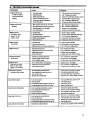
Engine wilt not sta_
or will runonly for
a few seconds after
starting
,,, ,, ,
i i ii
iiiiii
,,,
,,,,,,,,
,,,
,,,
CAUSE
REMEDY
I.
2.
3.
4.
5.
6.
1. Fill ta_ with correct fuelmixture.
2, See "S_aing lnstrudious?"
3, Install new plug/check ignition system.
4. Ctean fuel fdter; inspectfuel line.
5. See "Csrburctor Adjusanents:"
6. Contact your Sears Service Center.
Fuel tar&empty.
Engineflooded.
Sparkplug not firing.
Fuel not reaching carburetor.
Cadmretorrequiresadjustment.
Noneofthe above.
,,_
Engine will not idle
properly
u_
I. Idle speed set too fastor too slow.
1..See"Carburetor
Adjustments:"
2. See"C_oburetor
haljustmentsY
3. Loosenscrew to free tfigger.
2. Iz_ speed mixturerequires
adjustment.
3. Throtd¢trigger screw too light.
4. None of the above.
,,,,, ....
,
4. C0mact your Sears Service Center.
,,,
Engine will not
accdcrate, lacks
power, or dies
.undera load
I- Air fiJter€lirty.
2, Sparkplug fouled.
3. Carburetcwrequiresadjustment.
4. Muffler
outlets
p!ugged.
5. Noneoftheabov_
Engine smokes
excessively
L Air fdterdirty.
2, Fuel mixture incorrect.
3. .lslguS_
•,:_L __.., mlxrdre requires
__
aujustment.
_.,-
Engine tans ho_
I.Fuelmixtureincorrect.
2. Highspeed
mixture
se_
tooIow(lean).
1. Clean oi"replaceair Idler.
2, Cleanor replace spark plug and regap.
3. See "'Carburetor
Adjustments:"
4. Contact ),ourSears Service Center.
5. Contact your Sears Service Center.
I. Clean or replaceair fiher.
2. Refuel withcorrect fuel mixture.
Adjustments."
, .....3. See "Carburetor
• .....
,
,, ,j
3.Spark
plug
ineomxt.
4_ Noneoftheabove.
,,..........
Trinaner headturns
at idle speed
,, ,,,,,,
I.Carburetor requiresadjustment.
2. Throtlle trigge_rscrew too tight.
3. Clu_h requiresrepair.
--Ttimme_ead__
stops under a load or
does not turn when
engine is accelerated
I
_fiv_
L See "Carburetor Adjustments:"
2. Loosen screw to free trigger.
3. Contact your Sears Service Ceqter.
..... _!_. _R_laceor see
"_Assembl
.y__._
2. See "Ca_uretor Adjustments?"
3. Contactyour Sears Service Center.
_hafihmk_.nnrnotenoagcgt
2. Carburetor requiregadjustments.
3. Clutch requiresrepair,
,
r
,
or breaks while cutt!ag
,,
,,,,,,,,
,,,
,, ,,,,,, ,,,,,,,
L
2.
3.
4.
,,,,,
I, Removecover. Check line routing.
Line improperly'routedin head.
Line improperlywound onto spool,
Line size incorrect.
Toolittle line outside head.
,,,
2. Rewiadline 6ghtly and evenly. ®
3. Use onlyDSO"Sears LaserLine .
4. Remove cover. Pull6" of lineto outside.
, ,,,,,,,,
,,
,,
Line welds oa spool
Linesize incorrecL
2. Incorrect spool.
3. Crowd_g line against materia! being cut.
Cutting at higher speed httan necessary. -
L Useonty Dg0" Sears Laser Line®.
2. Use proper spool.
3. Cut wilhtipofline.
Line releases continuously
I.
2.
3.
4.
L Rewindline tightly and evenly•
2. Remove cover. Check line routing.
3. Use only.080 _Sears LaserLine
®."
Line usage is excessive
Line pulls back into head"
.............,,,,,,,,
I.See "Fueling YourUnit:"
2. See "Carburetor Adjustments:'
3.Replace with correct plug.
4.
I.
Line wound beyondnotches on spool.
Line improperly routed in head.
Line size incorrect.
Shield installedimproperly.
4. Reinstall s,hield properly.
1, Line impropedy mutedin head.
2. Linesize incorrecl,
3. Ctittingat high speed aronnd hard objeCts.
L Remove cover.Check line routing.
2. UseonlyDS0"Sears
laserLine®•
3. Re.Auees_aro_dhardo_jecls-
4. Crowding line against material beingcut1, Toolittle line outside of head
4• Cut withtip of line.
I. Removecover. Pull 6" of line tooutside,
2I
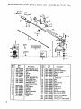
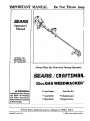
SEARS WEEDWACKER®
REPAIR
PARTS LIST - MODEL 358.797161-32cc
22 23
31
27
32
i
14
,
NO,
1
2
3
4
5
6
7
,.8
-9
10
1t
12
13
14
i5
16
]7
22
530-027549
530-094694
SrD5_1025
530-010958
530-09_.3
71-85805
530-027595
530 -069252
530-O69256
,,,,,,,
Part
No,
Description
Throttle Cable Ass'y.
Drive Shaft Housing
Nut:
Handle
Screw
CUtting Head _A_s'y.
(Ind. # 15,16& 17)
Drive Shait Grip
_T" Handle" Ass'y.
Shield F.it Ass'y.
(Ind. #10,11 & 12)
STD511005
Screw
530-094570
Line Limiter
530-015653
-Locknut
530-094639
Dust Cup
530-030139
Shaft Lubrication
.53O-094557
Hub Ass'y
,..71-85815 .......: ....SpoolxvtLine
530.09449¢
. Cover
.
18
19
2O
21
22
23
530-094585
_530-067877
Description
DrFce Shaft
Operator'v Manual
530-094568 _ Gear Bo_ Ass'_
530-015775
530-015774
530-010959
Screw
Screw
Throttle
LeverAss'y.
(Incl.
#22,& 24)
24
25.
26
27
28
29
3O
31
32
33
101
102
103
530-015768
530-094640
530-094571
530-094616
530-094612
530-015328
530-001642
530-001'711
530-031111
530-031098
530-029159 '
530-029763
530-029764
Se_
G_
Washer
Screw
_CT_W
Lackvcasher
H_ Wre_ch (5/32)
I-Ie_ W_:v_.cb (3[16)
D¢-:_---_haC_ Warning
-D,c_--Eh_dd
Da<_._--1_.¢:_- Vibe Handle
i
\
_s
e
\
\
T
\
¢_j__
\
t/r
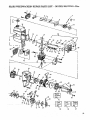
SEARS
Key
No.
WEEDWACKER
Pail
No.
5
6
7
8
9
10
1I
12
I3
•14
Key
tNo,
i
,
Part
. ,,,,
Screw
Air Filter Cover
Air Filter
Screw
Spacer
Wave Washer
Choke Shutter
Air Filter Plate
Fuel Line Kit
Fuel Pick-up Ass'y.
Carburetor
_rCarburetor Gasket
Fuel Cap Ass'y.
Shroud & Tank Ass'),.
49
50
51
52
53
54
530-03OO77
530--015768
530 -O39136
530-347987
• 530"027517
530-069291
29
3O
31
32
33
34
35
36
37
38
39
40
41
42
43
44
45
46
47
48
530 -032103
530--015787
530--019158
530-032102
530 -069232
530-015777
530-027523
530-069257
530-024903
530 -015823
530-039134
530-015128
530--012235
19
2O
21
22
23
24
25
27
28
Description
NO.
530 -029395
530-027569
530-010961
530-094189
530-069254
• 530-010964
530-015767
530-027511
f (Incl.
#9,10 & 13) Gasket
62
530--015770
530-019154
Crankcnse/Shroud
63
530 -0/5769
530-027593
Reed
64
530 -015496
530-027594
P_
Stop
"
65
530-015788
530.--014015
CrankcaselCrankshaft
Ass'y. 66
53O-015796
(Incl. #20.21,28 & 66)
67
STD541137
530-010960
Connecting Rod Ass'y.
68
530-035464
Bearings)
09
530 -035166
530-015789
Crankshaft Retaining Ring
70
530-O35178
530-010934
Crankshaft Ass'y.
71
530-015126
Flywheel Key
72 . 530.--035106
530-035188
530-015772,
Screw
73
530-035031
530 -015780
Screw
74
530 --035028
530-027546+
Switch Insulator
75
--530---0275-47- .......Lead Wire
--76-- +_t4
530-035151
Screw
77
530-015771
530 -014016
Crankcase Ass'y.
530-035147
(Incl. #36-39)
78
530-035036
530--027545
Switch Ramp
530 -035142
530--027543
Switch Spring Ass'y.
530 -035141
STD610603
Screw
81
530--035023
53O-015162
Piston Pin Retainer
82
530--035208
530-025875
Piston Ring
83
530--035203
530-.019178
1 C'ylindetGasket
,,:.84.
53O-035260
530-069275
Piston Kit (Incl. #32,33,
85
15
16
17
18
24
530-015773
530 -027529
530-027530
530-015766
530-027528
530-015254
530-027526
530-027527
530-069247
530-010897
530 -035259
530-019156
530-010729
530-029675
PARTS LIST - MODEL 358.797161-32cc
Description
•
1
2
3
4
® REPAIR
& pin)
Inner Bearing
Retaining Ring
Crankshaft,Seal
Bearing Outer
Rope Kit
Screw
Retainer
Muffler Kit
Muffler Attachment Spring
Screw
Ignition Module Kit
Screw
Cylinder
55
. 56
57
58
59
60
61
86
530-035185
87
530 -069276
88
89
90
91
530-015239
530-015717
530-027781
952-701612
Spark Plug
Locknut
Flywheel Ass'y.
Washer
Fan Housing
Starter Pulley Kit
(Ind. #45)
Starter Spring
Starter Handle
PulIey Housing A_'y.
Clutch Washer
ClutchAss'y Kit
ClutchHousing
Screw
+Spacer
Screw
Screw
Scr_
• Spacer
Washer
Nut
*÷ Pump Gasket
"+ Pump Diaphragm
+ Inlet Screen
+ Inlet Needle Valve
+ Metering l._a,er Spring
+ Metering Lever
.+ Metering Pin
:
I-MeteringDiaphragm
*+ Metering Diaphragm
Gasket
*+ Circuit Plate Gasket
Hi Speed Needle Spring
Hi Speed Needle
Idle Needle
•Idle NeedleSpring
Idle Speed Spring
Idle Speed Screw
•
Carb. Kwik Repair FAt
( +Indicates Contents)
Cm'b. Gasket/Diaphragm
Kit (*Indicates Contents)
Engine Gasket Kit
(tIndicates Contents)
Screw
Screw
MufflerGuard
Spark Arrestor Kit
Not Shown
530-029734
530-061348
Instruction Decal
Carton
INDEX
AC_RIF_
..................................
10
ADJU_
Assist Handle ..................................
9
Carburetor.: ..................................
20
Line Advan_ .................................14
Module Air Gap ........._ .....................2
Spark Plug Gap ................................2
"Farotde Cable ..................................
8
AIR FILTER .....................................17
ASSFaMIILY
.Assist Handle ..................................8
Drive Shaft Housing ............................. 7
Preparation......................•..............7
Shield ........................................8
Throttle. Cable .................................8
Trimn_r Head .................................9
AUTOMATIC
LINE FEED ........................ 14
CARBURETOR
ADJUSTMENTS..
_................20
CARTON
CONTENIS
.............................6
COLD ENGINE STARTING .......................12
•CONTROLS
........... : ..........................2
CUTTING METHODS.
....."...................... 15
DRIVE SHAFT HOUSINGASSEMBLY
............. 7
ENGINE
Air Filter .......................................
17
Carburetor ................,....................20
Controls ......................................
Fuel Mixture
Starer Rope
..................................
.................................
2
I1
18
Starting Instructions .............................
12
Storage .....................................
5.1(3
Trouble Shooting ...._. ............"............22
ENGINE OIL
Rado to Gasoline .............................. II
_;
ndtto Use ........
..........
_....11
FILTER, AIR ................................
17
FLEXIBLE
DRIVE SHAFT LUBRICA_ON
..........19
FtmL
Gasoline/Oil
Mixture ....................."....'...
II
Mixing Fuel ......................
i ........... !!
Pouring Fuel ........................... . ......11
Safety........................................ II
Storage.......... _.......................... 10Jl
GASOLINE
Ratio to Oil ................................... It
Types to Use; notto Use ........................ II
GEAR
BOX LUBRICATION
.........................21
IDLE SPEED ADJUSTME/'_£.... ...................
... 20
Advance ... ................................14,22
Breaking ..........
-......................... 17. 22
Length tO Cut as Rep[acera,n{........... .........17
Operationtengthi ..............................
13
Replacement ...................................
16
Rewinding on Spool ............................
17
Routing in Head ............................... 16
Safety.........
................................ 14
Size to Use :........................ . .........17
Welding onto Spool .........
.................
13,17,22
Trouble Shoo6ng ...., ..........................
17, 22
LUBRICATION
Engitm .......................................
II
Flexible Drive Shaft............................19
Gear Box .....................................21
MAINTENANCE
Air Filter .....................................17
Carburelor .....................:..............20
Flexible Drive Shaft ............................19
Gear Box .....................................
19
Safety.........................................
1'7
Starter Rope ..................................IS
Trimmer Head ................................16
TroubleShooting Chart .........................22
MODULE &IR GAP ...............................2
OIL, ENGINE
Patio to Gasoline ..............................
II
TYPeSlt°
ON Us_; not to Use ........................II
OP EI_T
.Advancing the Line ............................14
Mowing .....................
,..................
I5
Pre43tperation Checks ..........................
12
Position ....................................
:.. 9
Safety ..................................
13,14
Scalping ....................................
:.. 15
Slatling the Engine .............................
12
Sp_d.., .....................................
t3
Stopping the Engine ............................13
Sweeping.....................................15
Trimming _...................................15
PAR'IS LIST .................."...............
23
PRE-OPERATION
CHECKS .......................12
PREWOUI_
SPOOLS .....-................•.......16
QUICK
REFERENCE
PAGE :......................27
REPAIR PAR'IS LIST ............................23
XAFETY-INSI'R_ON
,
..........
•SHIEU), ASSEMBLY ..............................8
SPARK P[J3G GAP
..2
SPARK ARRF_R
...............................6
SPECIFICATIONS
............................... 2
SPOOL
•Installation ............................: .......16
Maiitte4"xance ..................................16
Prewound.....................................16
Rewinding......... ...........................17
STARTER
ROPE REPLACEMENT
.................18
STARLING
INSTRUCTIONS
......................12
STORAGE
.....................................5,10
THROITLE
CABLE ASSEMBLY ...................8
TRIMMER
HEAD
Assembly . ................ _...........-....:,.g
Line Routing ..................................
16
Removal .......................................
Maintenance ........................
TROUBLE StIOOTING
CHART
8
"...........
16
...................22
WARM ENGINE STARTING ......................
12
WARM ENGINE STaG
_
RUNNING
OUT OF FUEL _ ............................. 13
WARNINGS AND SAFETY INSTRUCTIONS
.....3 & 5
W__
"
...... 2
25
f
QUICK
REFERENCE
PAGE
Read and FolloW AU Warnings, Safety Ins_ctions,
and Operating
Failure to do so can result in serious injury.
lnsWuaions.
' Page No_
PREPARAT/ON
L
2.
3.
4.
5.
....................................................
3 b' 5
Know all warnings and safety instructions in this manual.
Wear safety face shield or goggles for eye protection,
Dress safely - boots or safety shoes and heavy, long pants.
Chec[_ tool for worn. toose, missing, or damaged parts: repair or replace as necessary before using the tool.
Inspect and ensure thearea to Ix: cut is safe.
6. Keep children, bystanders, andanimals
FUELING
30foet away.
..................................................
11
i, Eliminate all sourc_ of sparks or flame where fuel is mixed, poured, or stored.
2. Us_ 40 parts regular unleaded gasoline to 1 part air-cooled, 2-cycle engine oil.
3. Use clean and fresh fuel.
4. Mix and Store fuel in an appi'oved, marke_dcontainer.
-5.-Mi:x'_ndpom ,_ucli, _l uardo_'_.
6. Move a minimum of 10 feet away from the fuel and fueling site before starting engine.
START/NG
I.
2.
3.
4.
THE
ENGINE
........................................
Extend line 6 inches from the head.
Rest the shieldon the ground supportingthetrimmerhead
Keep throttle trigger squeezed fully until engine runs.
Pull _€ starter rope sharply and quic_y.
OPERATING
THE
TOOL
1.2
upoffthe ground away from objects and oa4ookers.
-
1.3
!. Do not operate the tool at a higher speed than necessary.
2. Release the throttle trigger and allow the engine to idle when not cutting.
3. Stop the engine by moving the ignition switch to the "Off" position.
_..MANCE
I.
2.
3.
4.
26
"k
_
a
_
v
4
e
•
•
•
_e
e
e
•
•
e
_
o
,o
o
g,
4
_
e
4P o
e
4J
a
44
*
_
m,m,e
Run fue! from the unit before storing, -.
Disconnect spark plug before performing maintenance except for carburetoradjustments.
Clean air fil_r frequemly but always after :5r_nks of fuel.
Store in a dry place out of the reach of childrem
•
O g
q,B
_
4
e
t
4
e'_
17
The Model Number will be found below the top handle with the Serial
Number. Always mention the Model Number when requesting service or
repair'parts for your unit.
All parts listed herein may be ordered from any Sears Service Center
and most Sears Stores.
Operator's
WHEN ORDERING REPMR PARTS ALWAYS GIVE THE FOLLOWING
INFORMATION
AS SHOWN IN THIS LIST:.
Manual
1. The PAI_ NUMBER
3.. The PART DESCRIPTION
2. The MODEL
4. The NAME
35&797161
NUMBER
OF ITEM
26ccGas Weedwecker®
If the parts you need are not _ocked locally, your order will be transmitted
to a Sears P..epalrPmt_Distribution Center for handling.
MODEL
NO.
When you buy merchandise from
Sears you get an extra veltte that
nobody else can offer _ Sears
Service.
358.797161.32cc
(18" Cutting Pa(h)
Acrosstown oracross
thecountry,
Sea.rs Service is Mways near, pro.
riding trustworthy,, competent
:service technicians using
only
How-toOrder
Repair
Parts
SEARS
-Sears-specified=f_cto_,l_arts: ........
Your Sears Merchandise takes on added value when you discover
that Sears has Service Units throughout the country. Each is
staffed by Sears-Trained, professlona] technicians using Sears ilpproved methods.
SERVICE
IS AT YOUR
•
SERVICE
Sold.by
Sears,..Roebuck
andC, o., Chicago_ tL 60684
U.S,A_
i
S30-067877-6-03/31193
.
PRINTED
IN U.S.A.